

Page 1
OPERATING MANUAL
for
Separator Compact
Version: I- 2014
Page 2
II
Operating Manual for Bauer Separator Compact
S
Thank you for buying a BAUER separator!
This operating manual is an important document that describes the operation and maintenance of
the BAUER SEPARATOR.
All information contained in this manual is based on the latest product details available at the time of
printing. If you need still more information, please ask your dealer or contact the BAUER company
directly.
Please note that the content of this manual neither constitutes part of nor alters in any way any previous or existing agreement, promise or legal relationship. BAUER’s obligations are based solely on
the respective purchase contract, which also contains the complete and only valid warranty agreement. Said contractual warranty is neither extended nor limited by the content of this manual.
The BAUER SEPARATOR is designed for safe and reliable operation provided it is operated in accordance with this operating manual.
You should therefore study this manual thoroughly before starting your BAUER SEPARATOR! Strict-
ly observe all instructions pertaining to system handling, operation and service!
If these conditions are ensured, the BAUER SEPARATOR will operate to your complete satisfaction
for many years to come.
The content of this operating manual is the intellectual property of the company BAUER GesmbH
and/or its supplier companies. The available information may only be used in connection with the creation of specification-compliant documents in the course of an order from the BAUER company.
Without express written permission from the BAUER company, no reproduction or sharing of this
operating manual is permitted, even in excerpts.
The BAUER company reserves the right to make changes at any time without notice and without assuming any liability!
In the interests of a clearer presentation and due to the large number of possibilities, this operating
manual does not contain all detailed information and, in particular, cannot address every conceivable
operating and maintenance situation.
WARNING
Failure to follow this manual may cause personal injury or damage the
equipment!
NOTE
This manual is to be considered an integral part of the BAUER SEPARATOR. Sup-
pliers of both new and used systems are advised to put down in writing that they
delivered the manual together with the system.
Please make this manual available to your staff. State the pump type and serial number of your
BAUER SEPARATOR in all inquiries, correspondence, warranty problems or parts orders. You will
find this information on the type plate riveted onto the screen housing of the separator.
We wish you great success with your BAUER SEPARATOR!
Page 3
Operating Manual for Bauer Separator Compact
1
PRODUCT DETAILS
Type designation:
Separator Compact
Serial number1:
Dealer:
Name:
Address:
Tel. / fax:
Shipping date:
Producer of the machine:
Röhren- und Pumpenwerk BAUER Ges.m.b.H.
Kowaldstr. 2
A - 8570 Voitsberg
Tel.: +43 3142 200 - 0
Fax: +43 3142 200 –320 /-340
e-mail: sales@bauer-at.com
www.bauer-at.com
Owner or operator:
Name:
Address:
Tel. / Fax:
Note: Make a note of the type designation and serial number of your separator and its accessories.
Include these numbers along with all contact with your dealer.
1
It is very important to include with all guarantee claims and all correspondence related with this machine the entire serial number group, including all letters, both for the machine and for its relevant
components. This point cannot be stressed enough.
Page 4

2
Operating Manual for Bauer Separator Compact
S
TABLE OF CONTENTS
1 GENERAL SAFETY INSTRUCTIONS ............................................................................................................... 4
1.1 Warnings and Symbols ................................................................................................................................ 4
1.2 Duty to Furnish Information ......................................................................................................................... 4
1.3 Product Liability............................................................................................................................................ 4
1.4 Qualified Operators ..................................................................................................................................... 5
1.5 Intended Use ............................................................................................................................................... 5
1.6 Unauthorized Modification and Manufacture of Replacement Parts ........................................................... 5
1.7 Disposal ....................................................................................................................................................... 5
2 GENERAL INSTRUCTIONS FOR SAFETY AND ACCIDENT PREVENTION .................................................. 6
3 FUNCTION DESCRIPTION ................................................................................................................................ 9
4 SETUP OF THE SEPARATOR ........................................................................................................................ 10
4.1 Installation Diagram ................................................................................................................................... 10
4.2 Condition of the BAUER Separator upon Delivery .................................................................................... 10
4.3 Required Tools .......................................................................................................................................... 10
4.4 Features, Identification and Information .................................................................................................... 11
4.5 Type plates - Information Signs ................................................................................................................. 12
4.5.1 Information on the Separator Type Plate ........................................................................................... 12
4.5.2 Information Signs................................................................................................................................ 12
4.6 Separator Technical Data .......................................................................................................................... 12
4.7 Setup and Assembly .................................................................................................................................. 13
4.8 Complete System ...................................................................................................................................... 14
4.8.1 Inflow Setup ........................................................................................................................................ 15
4.8.2 Drainage Line ..................................................................................................................................... 15
5 ELECTRICAL CONNECTION .......................................................................................................................... 16
5.1 Setup and Operation of the Motor ............................................................................................................. 17
5.2 Condensate Hole ....................................................................................................................................... 17
5.3 Installation Without Switch Cabinet ........................................................................................................... 17
6 PREPARATION FOR INITIAL STARTUP ........................................................................................................ 18
7 INITIAL STARTUP ........................................................................................................................................... 18
7.1 Configuration Instructions .......................................................................................................................... 18
7.2 Solid Cake Formation ................................................................................................................................ 19
7.3 Configuration to Stabilize the Solid Cake .................................................................................................. 20
7.3.1 Cake Too Firm .................................................................................................................................... 20
7.3.2 Cake Too Soft .................................................................................................................................... 20
7.4 Additional Instructions for Flawless Operation .......................................................................................... 21
8 WINTER OPERATION ..................................................................................................................................... 21
9 TEST FOR SEPARATION CAPABILITY ......................................................................................................... 22
10 LIQUID CLEANING .......................................................................................................................................... 23
11 IMPORTANT ASPECTS TO BE CONSIDERED DURING OPERATION ........................................................ 23
12 TAKING THE SEPARATOR OUT OF OPERATION ....................................................................................... 23
Page 5

Operating Manual for Bauer Separator Compact
3
13 MAINTENANCE AND INSPECTION ................................................................................................................ 24
13.1 Gearbox and Motor ................................................................................................................................ 24
13.1.1 Supply with Sealing Medium ............................................................................................................... 24
13.2 Inspection of the Sieve and the Guide Rails .......................................................................................... 25
13.3 Inspecting and Reinstalling the Sieve .................................................................................................... 27
13.4 Inspecting and Reinstalling the Screw ................................................................................................... 28
13.5 Evaluation Criteria for the Screw and Sieve with Regard to Wear and Refurbishing ............................ 29
13.6 Summary of Maintenance and Inspection Intervals ............................................................................... 30
14 PROBLEMS - TROUBLESHOOTING.............................................................................................................. 31
14.1 Principles of a “Normal” Operating Condition ........................................................................................ 31
14.2 Troubleshooting ..................................................................................................................................... 32
15 ACCESSORIES ................................................................................................................................................ 35
15.1 Separator Control ................................................................................................................................... 35
15.1.1 Motor protection circuit breaker F1 ..................................................................................................... 35
16 NOTES .............................................................................................................................................................. 36
17 CONFORMITY DECLARATION ....................................................................................................................... 37
Page 6
4
Operating Manual for Bauer Separator Compact
S
1 GENERAL SAFETY INSTRUCTIONS
This operating manual contains important information that must be observed during setup, operation
and maintenance. For this reason, it must always be read and observed very carefully by the installation technician as well as the qualified personnel. It must always be available at the usage location of
the machine.
If the installation and maintenance are not carried out according to the operating manual, all warranty
claims due to faults become void.
The customer is responsible for the proper setup of all equipment. Read the instructions before assembling or installing the machine. Promised performance characteristics of the machine and the addon components as well as the fulfillment of any warranty claims are dependent on compliance with
these instructions.
The CE mark applied by the manufacturer provides external verification of the machine’s conformity with the provisions of the Machinery Directive and with other
pertinent EC directives.
1.1 WARNINGS AND SYMBOLS
The following notes and warnings are used in this operating manual for especially important instructions:
DANGER
Information, requirements or prohibitions to protect against serious injury or
property damage.
WARNING
Special information on preventing minor injuries or requirements and prohibi-
tions to prevent damage to the machine.
NOTE
Special instructions to simplify working with the machine or to aid in efficient use
of the machine.
To prevent malfunctions that could directly or indirectly result in serious injuries or property
damage, it is equally important to comply with any other instructions concerning transport,
assembly, operation and maintenance as well as reference data (in the operating manual, the
product documentation or on the equipment itself).
1.2 DUTY TO FURNISH INFORMATION
When passing the machine on to a new owner, the customer is obliged also to hand over the operating
manual to the new owner. The recipient of the machine must be instructed with reference to the mentioned regulations.
Should you encounter difficulties in understanding this manual or other instructions, contact the respective dealer or the BAUER company for
any necessary clarifications.
1.3 PRODUCT LIABILITY
According to the Product Liability Act, every farmer is an entrepreneur!
In accordance with Section 9 PHG (Product Liability Act), liability for damage to physical property
caused by defective products is expressly excluded. This exclusion of liability also applies to parts not
manufactured by BAUER itself but purchased from external suppliers.
Page 7

Operating Manual for Bauer Separator Compact
5
1.4 QUALIFIED OPERATORS
These are persons who on behalf of their training, experience and instruction as well as their
knowledge of relevant standards, rules, precautions to be taken for accident prevention and prevailing
operating conditions have been authorized by the person in charge of system safety to perform the
respective tasks required and in doing so are able to recognize and avoid potential hazards. The statutory minimum age for the operating and maintenance personnel must be observed. Among other
things, knowledge of first aid procedures is also required.
1.5 INTENDED USE
The BAUER separator is designed exclusively for solid-liquid separation in agricultural applications
(intended use).
Any use of the machine beyond this intended use is considered non-conforming. The manufactur-
er is not liable for damage resulting from such non-conforming use, the sole liability for damage
from non-conforming use lies with the user.
Intended use also includes compliance with manufacturer’s operating, maintenance and service
instructions.
The BAUER separator may be used and operated only by persons who are familiar with the sys-
tem and aware of the hazards involved.
All relevant rules for accident prevention as well as any other generally accepted rules and regula-
tions relating to safety, occupational medicine and traffic laws must be strictly observed.
Unauthorized modifications to the machine release the manufacturer from liability for damage re-
sulting from such modifications.
1.6 UNAUTHORIZED MODIFICATION AND MANUFACTURE OF REPLACEMENT PARTS
Modifications or alterations to the machine are only permitted after consultation with the manufacturer.
Original replacement parts and authorized accessories from the manufacturer serve the interests of
safety. The use of other parts voids the manufacturer’s liability for any resulting consequences.
The replacement parts used must correspond to the technical requirements established by the manufacturer of the system. The replacement and wearing parts delivered with the machine or via subsequent orders satisfy this condition.
1.7 DISPOSAL
The machine must be disposed of according to the local disposal regulations.
The user must ensure safe and environmentally friendly disposal of operating materials and ancillary
materials as well as replaced parts. Dispose of oil, grease, and filters in accordance with regulations!
Page 8

6
Operating Manual for Bauer Separator Compact
S
2 GENERAL INSTRUCTIONS FOR SAFETY AND ACCIDENT PREVEN-
TION
Check the operational safety of the machine before every start !
All regulations of public authorities that apply to the operation and maintenance of the system must be strict-
ly observed.
In addition to the operating manual, all generally applicable statutory and otherwise mandatory regulations
on accident prevention and environmental protection must be separately prescribed and observed.
Such obligations may concern, for instance, the handling of hazardous substances, the provision and wear-
ing of personal protective gear or traffic and road safety regulations.
The operating manual should be extended with the instructions for taking into account special operating
conditions, such as with regard to the work organization, work processes and the active personnel. The supervisory and reporting obligations of the operator must also be clearly regulated.
To ensure your safety and the safety of your employees, every person who is responsible for operating the
system must also be familiar with these obligations. It is too late for this when the system is already running!
The personnel assigned to operating the plant must have read the operating manual and in particular the
section “General Instructions for Safety and Accident Prevention" before starting work.
Every person must be aware of the safety measures that must be complied with during work on electro-
mechanical components and machines.
Only trained personnel may enter the hazard zone of the machine.
Only trained personnel may be assigned to work with the machine. The respective competencies of the
personnel for the operation, setup, maintaining and repair of the machine must be clearly defined. It must
also be ensured that only appropriately authorized personnel work on the system.
Personnel who are being trained, taught, instructed or are participating in a general training program may
only work on the system under the constant supervision of a person experienced in operation of the system.
The safety- and risk-conscious work by the personnel in compliance with the operating manual must be
checked at least at certain intervals.
The personnel assigned to operate the machine may not have:
Exposed long hair
Loose clothing
Jewelry, including rings and drop earrings
Such items could get stuck and/or drawn into the machine, resulting in possible injuries.
The operating personnel of the system must be familiarized with the fire alarm and fire-fighting options.
The wearing of personal protective gear such as hearing protection, safety glasses, safety shoes, etc. dur-
ing operation of the system must be required by means of rules or regulations.
All safety information and warnings present on the machine must be pointed out, and these must be kept on
the system in a clearly visible and legible condition.
In event of safety-relevant changes to the system or its operating behavior, the system must be immediately
shut down and the fault must be reported to the competent person or office.
Replace pipelines and hoses in the specified or otherwise reasonable intervals, even if no operationally rel-
evant defect is discernible.
Intervals that are required or specified in the operating manual for regular daily, weekly and monthly inspec-
tions and tests must be complied with. Appropriate tools and equipment must be kept available for the performance of such work.
Any potentially unsafe work on the machine must be avoided. The system may only be used in accordance
with its intended use. All necessary measures must be taken to ensure that the system is only operated in a
safe and fully functional condition.
The system may only be started up if all protective and safety-related features are fully functional. This in-
cludes the fact that all removable protective features, EMERGENCY STOP buttons and covers must be
present and functional.
WARNING
Page 9

Operating Manual for Bauer Separator Compact
7
The system must be inspected for externally identifiable defects before it is started up each time. Any
changes that occur, including changes to the operating behavior and functional disruptions, must be immediately reported to the competent party. The system must be immediately shut down and secured.
Procedures for switching the machine on and off as well as inspection of the control indicators must be car-
ried out as described in the operating manual.
Before switching on or starting up the machine, it must be ensured that no one will be endangered by the
starting up of the machine.
The correct functioning of the controller must be checked before the start of work. Before startup, all tools
and assembly aids must be stored safely to prevent accidents.
The maintenance, configuration and inspection activities and deadlines specified in the operating manual
must be complied with. The specified deadlines are maximum deadlines and may not be exceeded. Such
work as well as the replacement of components may only be performed by qualified personnel.
During transport of the separator, measures must be taken to ensure sufficient securing of the transport ar-
ea.
The required switch-on and switch-off procedures according to the operating manual and the instructions
for maintenance work must be observed during all work involving the operation, production adaptation, conversion or configuration of the system and its safety-related features as well as all work involving inspection,
maintenance and repair.
The operating personnel must be informed of special work, repair work or conversion work in a timely fash-
ion prior to starting the work. A supervisor must always be appointed during the performance of such work.
The work area must be blocked off and secured by a wide margin during such work, if necessary. Unau-
thorized persons must be prevented from entering.
As a rule, maintenance and cleaning work as well as repairs of malfunctions may take place only with the
drive switched off and the motor at rest (switch off and lock the main switch or disconnect the supply of
electricity).
Watch out for the unexpected starting of the system.
It must be noted that a pressed EMERGENCY OFF button does not provide any protection against unau-
thorized starting of the machine.
During disassembly and assembly, large individual parts and entire assemblies must be carefully fastened
and secured to lifting equipment. Only suitable lifting equipment and load handling devices with sufficient
carrying capacity and no technical operating defects may be used. Standing or working under suspended
loads is not permitted. Grips, steps, railings, landings, platforms and ladders must be cleaned of oil, dirt,
snow and ice before all activity on the system.
If the BAUER separator is installed on an elevated platform, this must be equipped with a railing. The plat-
form should be sufficiently dimensioned to allow maintenance and service work.
Any openings in the platform must be sufficiently secured against tripping or falling through.
Access stairs must be equipped with hand rails in accordance with applicable regulations.
If access stairs cannot be used due to tight space conditions, permanently mounted ladders with back pro-
tection must be used.
Securing of personnel with suitable supporting elements is required during all maintenance work on an ele-
vated system.
During assembly work above head height, climbing aids and work platforms intended for such work or spe-
cially adapted for purposes of safety must be used. Never use system components as climbing aids. The
system and, in particular, connections and bolt connections must be cleaned of oil, grease or care agents
prior to the start of maintenance or repair work. No aggressive cleaning agents may be used. Only fiber-free
cleaning cloths may be used.
Before cleaning the system with water, steam, high-pressure cleaners or other cleaning aids, cover / tape
over all openings into which no water, steam or cleaning agents may enter for safety and/or functional reasons. Electric motors and electronic switch cabinets are at particular risk. After cleaning, the applied covers
/ tape must be completely removed again.
Wear appropriate protective gear to protect against flying particles while cleaning with compressed air or
steam jets.
After cleaning, all gear oil and media lines as well as all electrical connections must be inspected for leaks,
loosened connections, abrasions and damage. Identified defects must be corrected immediately.
Page 10
8
Operating Manual for Bauer Separator Compact
S
The bolt connections loosened during maintenance and repair work must be tightened again. Observe the
required tightening torques.
If it is necessary to remove safety features during maintenance, setup or repairing, the safety equipment
must be re-installed and inspected immediately after completion of the work.
Do not start the machine unless all guards and safety devices are mounted completely and in proper work-
ing position!
Protective caps and covers may not be removed.
The stickers affixed to the device with safety and warning signs provide important instructions for safe op-
eration; following these instructions is intended to keep you safe! These may not be removed.
Check the proper seat of nuts and bolts regularly, and tighten them, if needed!
When replacing operating elements with blades, use a suitable tool and wear gloves.
The system is electrically operated. Take special care when performing work in the area of electrically op-
erated system components.
Work on electrical and electronic components of the system may only be performed by a trained electrician
or otherwise appropriately trained personnel under the guidance and supervision of a trained electrician in
accordance with the applicable electrical and electronic regulations.
With regard to an ATEX 95 zone 22 certification, see the special remarks.
Never touch rotating or moving parts of the machines with hands or feet.
Never reach with hands, tools or other parts over the inflow or hopper in the area of the auger while the ma-
chine is running.
In handling slurry, always remember that the gases produced by the slurry are highly toxic and explosive in
combination with oxygen. Open flame, light checks, spark creation and smoking are therefore prohibited!
When using the retention or alternating retention method, special care must be taken in the area of the
opened sliding gates to the pre-pool before the main tank or to cross channels due to the formation of gases. In addition, special care is required at stirring and withdrawal points while the stirring machines or
pumps are active!
Keep the machine clean to decrease the risk of fire!
Always ensure sufficient ventilation when working with slurry!
When working with biologically active materials in connection with the BAUER separator or connected com-
ponents, the decomposition of these materials can lead to the production of life-threatening gases, especially in enclosed spaces. Always ensure sufficient supply and exhaust ventilation and/or appropriate protective clothing before entering such areas.
DANGER
In addition to the mechanical dangers of moving parts or parts under pressure, the operation of slurry handling machines also poses risks in connection with gases produced by
liquid manure. These gases (carbon dioxide CO2, ammonia NH3, hydrogen sulfide H2S, methane CH4) can result in poisoning as well as explosions.
Especially when operating mixers, stirring machines, recirculation systems, pipe nozzles
and slurry aeration systems, care must be taken that no gases can flow into the stall from
exterior tanks or containers (install siphons or sliders).
Sufficient forced ventilation of the stall area must be ensured while handling slurry in the
stall area.
Page 11
Operating Manual for Bauer Separator Compact
9
3 FUNCTION DESCRIPTION
The BAUER separator serves for separating pumpable slurry (solid-liquid mixtures with relatively low
solid matter content and no foreign bodies such as metal parts, stones, wood or rags) into solid and
liquid (thin slurry) fractions. As a compact device, it combines the functions of two separators, specifically the functions of a screen and a press.
The BAUER separator is designed for sustained operation outdoors. It operates unimpaired in a tem-
perature range of 0-40 °C; in event of freezing temperatures, it must be ensured that the separator is
cleaned completely each time before being taken out of operation. Conditions of high humidity (e.g.
locations near to the coast) and extreme sunlight require special designs for the gears and motors.
Consult the manufacturer concerning such designs.
When selecting the feed pump and the overflow line, make certain that the separator is operated under
no pressure.
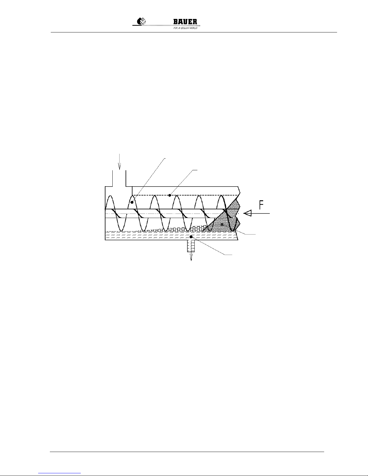
In the inflow area, the mixture is drained of water via gravity inside the screen. The interior auger
transports the pre-drained material horizontally toward the solid outlet. Along the last section of the
transport path, the auger presses out additional liquid, which escapes the separator through the screen
as thin slurry. The required contact pressure is applied to the escaping solid by a system consisting of
a cap loaded by a weighted lever.
The solid-liquid separation depends entirely on the type of slurry. For example, the extent to which water can be drained differs greatly between dairy cattle, beef cattle and pig slurry. Users of the BAUER
separator have many options for optimizing the separating result.
The throughput can be increased be selecting a larger screen gap width.
The residual moisture in the separated solid decreases as the contact pressure of the output
regulator is increased.
The solid matter content in the separated liquid can be reduced with a smaller screen gap width.
The degree of solid separation is improved by smaller screen gap widths.
More information about the configuration options can be found in section 7 “Initial Startup”.
Fig. 3-1 Function description
Raw liquid manure
Transport and pressing screw (19 rpm)
Sieve element
Solid phase
Liquid phase
Page 12
10
Operating Manual for Bauer Separator Compact
S
Ventilation
4 SETUP OF THE SEPARATOR
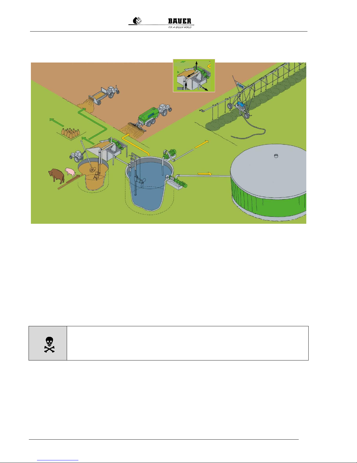
4.1 INSTALLATION DIAGRAM
4.2 CONDITION OF THE BAUER SEPARATOR UPON DELIVERY
The BAUER separator was developed by the company BAUER GesmbH. The separator is delivered as
a unit, including installed electric motor, on a pallet. The inflow element with outlet for overflow and
ventilation as well as the outlet bend are enclosed separately for easier transport and must be installed
before the initial startup.
You must connect the geared motor of the separator to the power supply of the optionally available
switch cabinet and connect this to the electricity supply. It is recommended that the corresponding
electrical control for the separator or for the separator and the Bauer submersed motor pump be purchased from BAUER since it will be already adapted to the corresponding drive motors.
Connecting the supplied hoses, if included, to the inflow and discharge connections of the machine
completes the installation of the BAUER separator.
DANGER
Work on electrical and electronic components of the system may only be performed by a trained electrician or otherwise appropriately trained personnel under
the guidance and supervision of a trained electrician in accordance with the applicable electrical and electronic regulations.
4.3 REQUIRED TOOLS
Special tools are not required for setting up the separator.
Standard tools for assembly and electrical tools are required for assembly, setup and disassembly.
The customer must check based on the dimensions and weight of the separator whether the available
lifting equipment (forklift, tractor with front loader, crane with corresponding belts or chains) is sufficient
for setting up the separator.
Distribution of the
solid phase
Sale of the solid
phase
Composting of
the solid phase
BAUER
Separator
Compact
BAUER MAGNUM
pump system
Distribution of the
liquid phase
via BAUER
slurry injector
Cerres
Distribution of the
liquid phase
via BAUER
Pivot or Rainstar
BAUER
submersed
motor pump
MAGNUM S
BAUER
slurry mixer
BAUER
submersed
motor stirrer
TMRW
BAUER eccentric
spiral pump Helix
Liquid
phase
Solid
phase
Inflow
Overflow
BIOGAS PLANT
Fig. 4-1 Installation diagram
Page 13

Operating Manual for Bauer Separator Compact
11
4.4 FEATURES, IDENTIFICATION AND INFORMATION
To make it easier for you to familiarize yourself with your new BAUER separator, Fig. 4-2 shows you a
longitudinal section of the internal machine design.
We assist every customer in optimally selecting the right main separator components for the specific
application before it is purchased, manufactured, assembled and shipped.
1
2
3
4
6 7
8
9
10
11
12
The precise article numbers of the wearing parts and the organization of the main components can be
found in the replacement parts list.
Item Part Item Part
1 Geared motor 7 Internal brace
2 Sieve housing 8 Weights
3 Press head 9 Housing protection ring
4 Double flap with rod 10 Sieve
5 Inflow element 11 Wearing profile
6 Screw 12 Sieve guide rails
Fig. 4-2 Main components
5
Page 14

12
Operating Manual for Bauer Separator Compact
S
4.5 TYPE PLATES - INFORMATION SIGNS
When you contact your dealer or communicate directly with BAUER GesmbH about wearing parts or
for technical support for your separator, you will be asked for your serial number and machine number
in order to ensure faster and more effective assistance.
The type, year of manufacture and serial number of the separator is indicated on the type plate riveted
to the screen housing near the inflow. Another type plate is located on the geared motor. Associated
details can be found in the enclosed geared motor documentation.
4.5.1 Information on the Separator Type Plate
The BAUER separator type plate contains the following information:
Separator type: Compact
Sieve used: e.g. 0.5 mm or 1.0 mm
Serial number: e.g. 1310389 (13 is the year, 10 is the month, 389 is a 3-digit counter)
4.5.2 Information Signs
The following information signs are located on the BAUER separator:
Red arrow on the mouth piece; indicates the correct rotation direction of the auger shaft
Yellow text field on the mouth piece; warns of a turning part
Yellow warning symbols on the housing shell; indicate that turning parts should not be
touched
Yellow text field on the geared motor; indicates the lubrication interval for the sealing
grease
Any damaged signs must be replaced. These can be ordered from your dealer.
4.6 SEPARATOR TECHNICAL DATA
Part name
Data
Material
auger, auger shaft
Screw with special surface hardening
Steel, stainless
Slotted screen
Available gap widths 0.25 / 0.35 /
0.5 / 0.75 / 1.0 mm
Steel, stainless
Bearing housing
Gray cast iron, painted
Separator housing
Gray cast iron, painted
Inflow, overflow, ventilation
BAUER inflow element 3x socket
DN100
Steel, galvanized
Bottom outlet bend
Pipe connection socket DN100
Steel, galvanized
Motor
3 kW, 50 Hz, 400 V, IP55, F,
Underframe
Steel, stainless
Gearbox
Cylindrical gearing 19.7 rpm (50
Hz)
Oil quantity and type – see type
plate on gearbox
Gray cast iron
Page 15
Operating Manual for Bauer Separator Compact
13
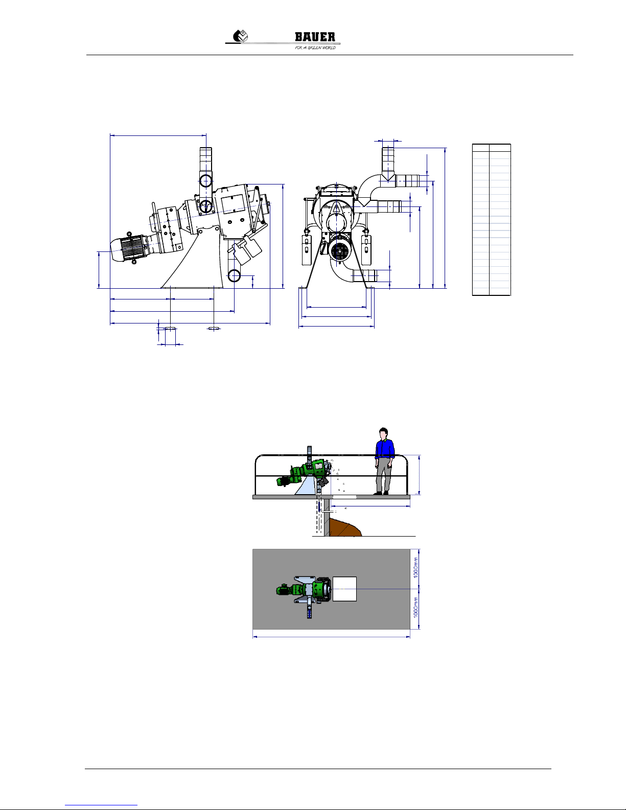
4.7 SETUP AND ASSEMBLY
The basic dimensions of the BAUER separator for determining the dimensions of the setup location
are shown in Fig. 4-3.
The dead weight of the Separator Compact is approx. 380 kg.
A B
C
D
E
O
H
O
G
O I
K
O
L
M
N
Q
R
P
S
T
O
F
J
Fig. 4-4 illustrates a suggestion for determining the size of the separator setup location.
It is very important that a clearance of at least 1100 mm or more is ensured in front of the mouth piece
of the separator. This clearance is required to remove the auger and the screen for maintenance. It
must be possible to remove the auger and the screen for regular inspections.
Width of the setup area: No less than 2000 mm
Length of the setup area: No less than 2900 mm
The surrounding clearance around the separator should be at least 1 m.
Handrail height of the setup area: No less than 1000 mm
Make sure that the mouth piece and the functioning of the separator can be clearly seen from the
switch cabinet. (It must be possible to watch the solid cake and its discharge speed.)
Fig. 4-3 Dimensions of Separator Compact
Fig. 4-4 Size of the setup location
[mm]
A 522
B 380
C 1080
D 1389
E 833
F 100
G 100
H 100
I 100
J 109
K 319
L 710
M 932
N 1220
O 904
P 515
Q 604
R 658
S 18
T 88
At least 1100 mm
At least 1000 mm
Solid
At least 2900 mm
Page 16
14
Operating Manual for Bauer Separator Compact
S
4.8 COMPLETE SYSTEM
The complete system of the press / screw separator also includes the material supply and discharge
handling.
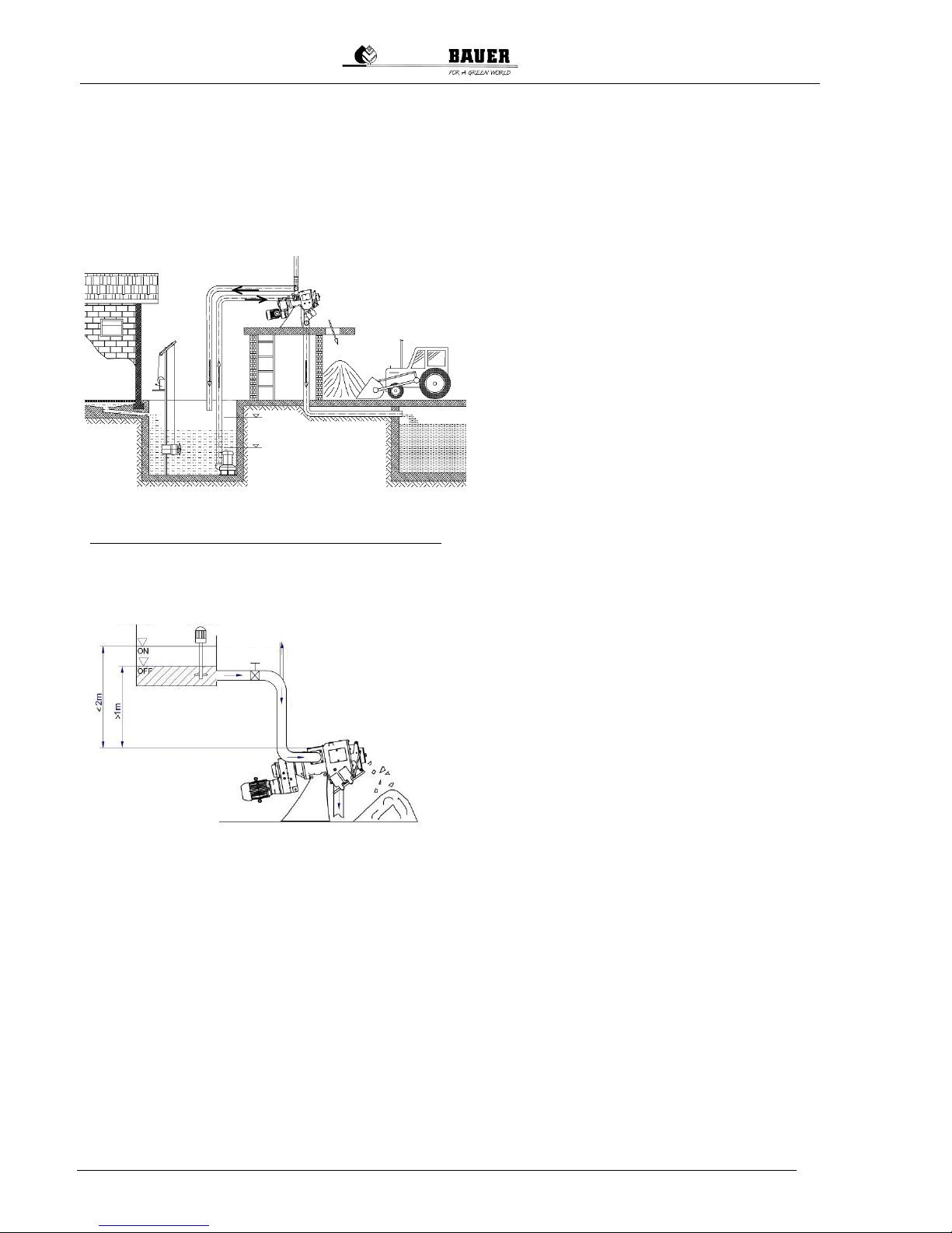
The incoming material can be delivered by pump or from an elevated tank by means of gravity. Because the pump delivery rate cannot be precisely determined, an overflow is absolutely required in
order to protect the separator from an overload.
The pump should be designed to slightly exceed the capacity of the separator, but the
pressure on the separator should not exceed 2
m water column [0.2 bar]. A higher pressure
would damage the seal in the separator.
In order to obtain a homogeneous mixture of
solid and liquid, a stirring machine is required
when supplying the slurry via a pump or from
an elevated tank.
It is very important that the supply of material to
the separator is always controlled by the switch
cabinet.
The correct selection of the pump, the stirring
machine and the supply and disposal lines is
critically important.
When supplying the separator from an elevated
tank by means of gravity, a flow regulator may
be required in some circumstances to limit the
pressure on the separator. In this case, an
overflow is not required.
The effluent should be disposed of via an open
(and thereby ventilated) drain channel or collected in a drainage pit and then pumped out in
order to avoid generating a suction effect on
the separator. The ventilation is required because otherwise particles are drawn into the
screen gap and remain stuck there, blocking
the open screen surface and impairing the
function of the separator.
The separated solid can be piled up and transported away as needed, brought away on a
conveyor belt or disposed of by container or
truck.
The supply line available with the BAUER separator as an accessory is a reinforced yet flexible tube.
This reinforced tube is resistant to negative pressure. Ventilation openings can be added to the inflow
line through the connection of a breather pipe to the inflow element. The ventilation is required for a
pump with a very high pump capacity since the high flow speed in the overflow line would otherwise
produce a siphon effect that would limit the supply to the separator and impair the separation process.
Fig. 4-5 Supply via pump
Fig. 4-6 Supply via gravity
from an elevated tank
Inflow
Stirrer
Overflow
Ventilation Open overflow Open drainage
Solid
Inflow
Mixer
Autom. valve
Ventilation
Inflow
Open drainage
Solid
Page 17
Operating Manual for Bauer Separator Compact
15
Abb 4.7 Standard-
Inflow
The separator must be set up so that the solid can be freely
discharged. There must be a corresponding height difference
between the solid discharge point and the ground. The volume
of the cone of discharged material can be determined based on
the setup height.
The overflow line for the raw slurry as well as the drainage line
of the separated slurry should drain without pressure into the
corresponding storage tanks.
The overflow line should be run without a “siphon” in order to
avoid a lifting effect and to ensure good separator throughput
(see also section 14 “Problems - Troubleshooting”.
Avoid winding, dipping and twisting of the pipeline and use tub-
ing that is resistant to negative pressure.
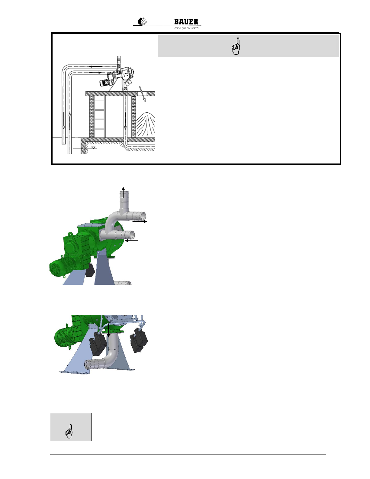
4.8.1 Inflow Setup
Screw the inflow element horizontally onto the inflow flange
(side of separator housing).
Connect the supply line to the lower horizontal connection
(socket DN100) of the inflow element. A tube of DN100 is required for this.
Connect the overflow line to the top horizontal outlet of the in-
flow element (socket DN100). A tube of DN100 is also required
for this.
A breather pipe or tube must be connected to the vertical con-
nection of the inflow element (socket DN100). This prevents the
buildup of negative pressure in the separator if the medium creates suction in the return line (siphon effect).
The breather tube should project at least 1.5 m above the overflow.
4.8.2 Drainage Line
flange (bottom of separator housing).
DN100 is required for this.
Connection or transition elements for tubes (for the inflow and drainage lines) are available as accessories from your dealer or the BAUER company.
NOTE
If no Bauer pump is installed, the pump for supplying the separator should have a pump rate
of at least 15 m³/h since the capacity of the separator otherwise cannot be fully utilized. To
keep pressure losses due to pipe friction low, the pipes should have a diameter of at least
100 mm (4").
NOTE
Inflow
Ventilation
Overflow
Open drainage
Open overflow
Ventilation
Abb.4-7 Inflow Setup
Fig. 4-8 Drainage line
Page 18
16
Operating Manual for Bauer Separator Compact
S
5 ELECTRICAL CONNECTION
The electric motor is equipped with a terminal strip. Like all electrical connections, the external motor
control must be connected properly by a qualified electrician.
DANGER
Work on electrical and electronic components of the system may only be performed by a trained electrician or otherwise appropriately trained personnel under
the guidance and supervision of a trained electrician in accordance with the applicable electrical and electronic regulations.
WARNING
Fuses do not protect the motor from overloads; they only protect the electrical
supply lines or switching systems from damage in event of a short-circuit.
The electric motor must always be protected with a motor protection circuit breaker that must be set to
the rated current shown on the type plate depending on the motor wiring. Only motor protection circuit
breakers certified according to the following standards may be used: IEC, UL, CSA.
WARNING
Set the motor protection circuit breaker to the correct value, never above the max.
rated current according to the type plate.
It is recommended that the corresponding electrical control for the separator or for the separator and
the submersed motor pump be purchased from BAUER since it will be already adapted to the corresponding drive motors.
WARNING
Ensure the correct rotation direction of the auger shaft when making the electrical
connection!
In forward motion, the auger shaft turns counterclockwise
(as viewed from the output regulator toward the geared motor).
If this is not the case, two of the current-carrying conductors
at the geared motor connection or in the switch cabinet must
be swapped.
Viewing
direction
Fig. 5-1 Rotation direction of the screw
Page 19

Operating Manual for Bauer Separator Compact
17
5.1 SETUP AND OPERATION OF THE MOTOR
The motors in the standard design are suitable for operation up to a maximum ambient temperature of
+40 °C (104 °F) as well as an elevation of up to 1000 m above sea level.
Conditions of high humidity (e.g. locations near to the coast) and extreme sunlight require special designs for the gears and motors. Consult the manufacturer concerning such designs.
The motors must be set up to allow unimpeded inflow of fresh air and dispersal of warm air. Removal
of the fan blade and the fan housing or enclosing the motor in a housing are prohibited since the supply of cooling air would be reduced in both cases. This would cause the motor to overheat.
For use of an original BAUER control, see section 15 Accessories.
DANGER
Before making changes or inspecting the motor or switch cabinet, the machine
must be disconnected on all sides and all poles and secured against reactivation!
Always keep the switch cabinet closed!
DANGER
It must be noted that a pressed EMERGENCY OFF button does not provide any
protection against unauthorized starting of the machine.
5.2 CONDENSATE HOLE
We recommend a condensate hole on motors that are subjected to high temperature fluctuations or
extreme climatic conditions.
DANGER
A motor protection circuit breaker or a protection device with overload relay must always
be installed to protect the motor winding. Fuses do not protect the motor from overloads;
they only protect the electrical supply lines or switching systems from damage in event
of a short-circuit.
5.3 INSTALLATION WITHOUT SWITCH CABINET
If the BAUER separator was delivered or ordered without a switch cabinet, a few basic rules
must be followed in controlling the separator; otherwise, the warranty is void:
The motor must be equipped with electrical protection to prevent impermissible current loads
exceeding the rated current on the type plate.
Operating the separator without an inflow of material must be prevented by means of electrical
control since dry running would otherwise result in increased wear on the screen and auger,
which would significantly reduce their service lives. For this reason, the separator should be
started up along with the start of the medium supply and stopped between 30 and 60 seconds
after the medium supply is stopped.
Page 20
18
Operating Manual for Bauer Separator Compact
S
6 PREPARATION FOR INITIAL STARTUP
Before beginning the startup process, check the following measures:
1. The separator must be firmly anchored to the ground.
2. Make sure that the mouth piece and the functioning of the separator can be seen clearly from
the switch cabinet [it must be possible to watch the solid cake and its discharge speed].
3. Check the rotation direction of the auger. As viewed from the mouth piece, the auger must turn
counterclockwise [if this is not the case, two phases must be swapped in the case of a 3-phase
power supply].
4. If the material is supplied by a pump, the rotation direction of the pump must also be checked
and corrected, if necessary.
5. A starter cake of solid material must be inserted for the startup, see section 7 Initial Startup.
6. Supply of sealing medium, see also section 13.1.1 When using grease as the sealing medium,
3 to 5 cm3 of grease must be introduced via the lubricating nipple [see Fig. 13-1] before initial
startup in order to fill the labyrinth seal.
7. Check the oil level in the gearbox and top up, if necessary; properly dispose of old oil.
8. Check: The supply line between the pump and the separator is connected and sealed; the overflow line is connected and sealed; open discharge into the storage container; line for drainage
of the separated slurry connected and sealed; open discharge into storage container.
9. Motor protection circuit breaker set to required rated current; after switching on, verify the correct rotation direction; note the arrow on the mouth piece; switch off the motor again.
10. Remove the weights (minimum closing force).
WARNING
It must be ensured that no large foreign bodies such as metal parts, stones, wood
pieces or rags enter into the separator; such objects would otherwise overload
the screen and the auger in particular. It should also be noted that abrasive media
(e.g. high sand content) will reduce the service life of the components.
WARNING
The filling components must be connected such as to prevent injuries and to
comply with the statutory regulations and safeguards.
7 INITIAL STARTUP
NOTE
In order to achieve good separating results, it is necessary to mix the pumped
medium well before separating.
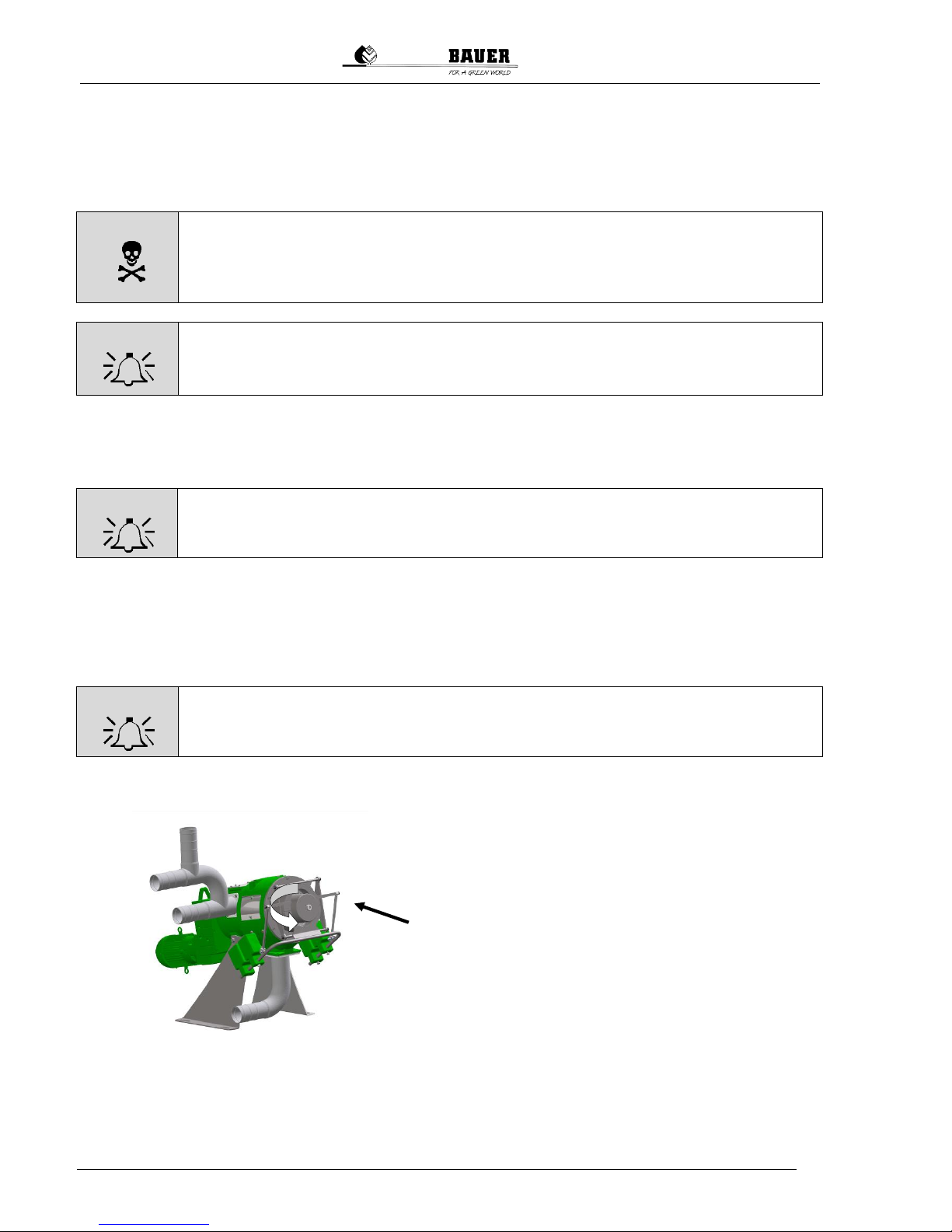
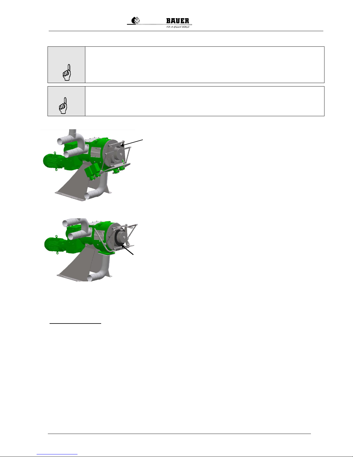
7.1 CONFIGURATION INSTRUCTIONS
Two weight arms and weights are available to stabilize the solid
cake and to adjust the dry matter content. These weights should
be affixed as necessary.
Fig. 7-1 Weight arms and weights
Page 21
Operating Manual for Bauer Separator Compact
19
NOTE
The reaction time before each setting change takes several minutes, meaning that the
effect of any change can only be determined after this time.
For this reason, always allow enough time after making a change and only make
changes in small steps!
NOTE
Before the initial startup and after prolonged downtime, the separator should be flooded
before switching it on by starting the pump briefly in order to prevent possible damage
from dry running.
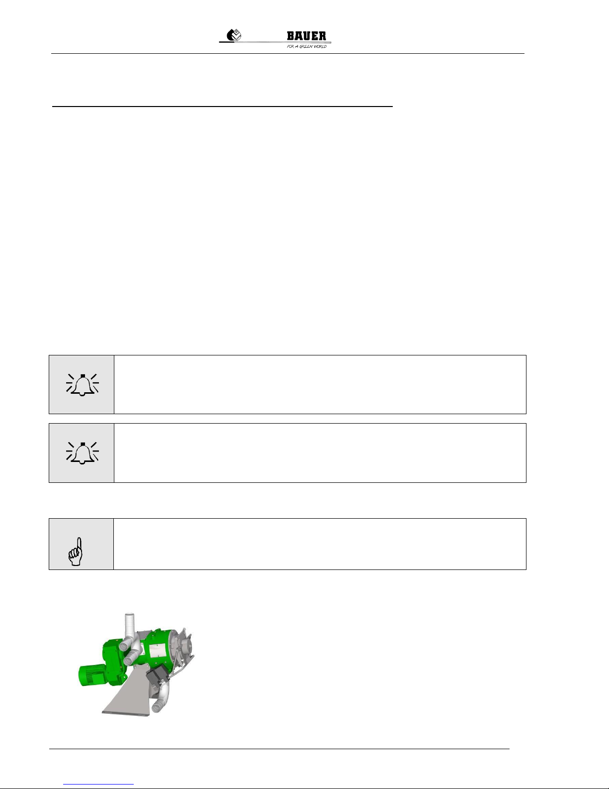
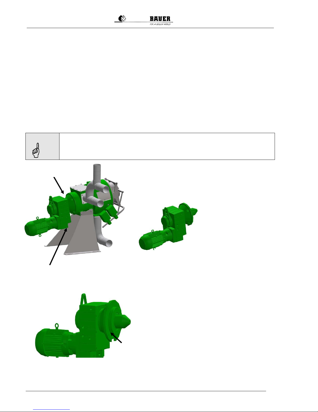
7.2 SOLID CAKE FORMATION
If no solid cake is present in the discharge area, it must be ensured that the discharge flaps rest fully against the mouthpiece.
After switching on the separator, start the pump only briefly - for
about 1 to 2 seconds, just long enough for the supply line and
separator to be filled. Then wait until liquid phase no longer runs
out and repeat the process.
Alternatively an artificial cake can be created.
To do this, place a cake formation aid made of foam rubber that
can be purchased as an option from BAUER behind the flaps or
firmly pack by hand some other fibrous material such as hay,
stray, silage, etc. behind the flaps. This starter cake is replaced as
the separation process continues by a newly formed solid cake
made of the separated medium, pressing out the starter cake. A
starter cake should be employed when the solid cake has been
removed from the machine for cleaning, inspection or maintenance purposes. If the machine is not operated for a prolonged
period of time such that the cake has either hardened, frozen or
become very soft, a starter cake is also required to restart the
separator.
To create a starter cake of paper or similar material, check before beginning work that the switch cab-
inet is disconnected from the electrical supply and is not energized.
Then do as follows:
1. Remove the 4 weights from the arms of the output regulator in order to open the regulator
flaps, then secure the flaps.
2. Insert the starter cake in the form of the cake formation aid made of foam rubber.
3. Or insert a starter cake of damp paper or similar material into the mouthpiece of the separator
up to the ends of the screw blade.
4. To be certain that the cake forms a sufficient seal against the liquid, this should be evenly compressed with a piece of round wood, for example.
5. Place one weight in each middle position on the output regulator arms. The pressure flaps of
the output regulator must rest against the starter cake such that pressure is applied to the cake
when the separator is started up. As a suitable solid cake is formed, the output regulator arms
will slowly move upwards.
The pump can then be switched on without pauses.
Fig. 7-2 Discharge flaps
Fig. 7-3 Cake formation aid
Page 22

20
Operating Manual for Bauer Separator Compact
S
Depending on the dry matter content (DM content) of the input medium, the solid cake will either already have the correct consistency with the initial setting of the weights or it will be either too soft or
too firm.
After formation of a cake and roughly 20 cm of DM throughput, the base settings should be corrected
again before the pump is set to continuous operation since the cake will otherwise “shoot out” if it is too
soft or clog the separator if it is too hard.
As a rule of thumb for a stable cake consistency, note the following:
The cake is too soft if the solid material is doughy, does not crumble, slides down a roughly 45° in-
clined surface rather than tumbling.
When pressed together (“normal hand pressure”) significant amounts of liquid comes out.
The cake is too firm if the solid material crumbles into very small individual pieces, does not break up
after emerging roughly 30 mm from the mouth piece, no water at all can be observed when pressing
together (“very strong hand pressure”).
These descriptions offer only a rough classification, and conditions depend heavily on the specific medium. The actual limits must be determined individually in practice.
These guidelines serve only to assess a stable cake, not to determine the dry matter content of the
solid phase.
7.3 CONFIGURATION TO STABILIZE THE SOLID CAKE
7.3.1 Cake Too Firm
Move the weights inward on the arms or remove them entirely.
If the cake is too firm, the separator may clog up after prolonged
operation since the cake can no longer be pushed out of the
mouthpiece!
In order for the cake to be ejected more easily, the weights can be
moved forward symmetrically. If this is not sufficient and the cake is
still so firm that even the motor protection circuit breaker is tripped,
the weights can also be removed entirely and the solid matter
pressed in only by the dead weight of the lid.
If there is a risk of the cake hardening during downtime, either a new
starter cake should be used for startup later, the weights on the lever arms should be reduced or the
cake should be softened with water. Never attempt to restart the machine with a hard cake in manual
mode via “jogging” since this can cause damage to the machine.
7.3.2 Cake Too Soft
If the cake is too soft, this can result in the cake “shooting out”; in other
words, the cake breaks up and unseparated medium flows out of the
solid side!
In order to make the cake harder and more stable, symmetrically move
the weights toward the back. Depending on the medium, the adjustments described above must be performed multiple times upon startup
until a stable condition is reached and the performance of the separator
is optimized.
Abb. 7-4 cake too firm
Abb. 7-5 cake too soft
Page 23

Operating Manual for Bauer Separator Compact
21
7.4 ADDITIONAL INSTRUCTIONS FOR FLAWLESS OPERATION
Make certain that the overflow does not produce a siphon effect.
This would produce unfavorable flows with too little solid matter entering the separator, lowering the
throughput while also interfering with the self-cleaning of the screen, which is activated by the solid
matter.
NOTE
For this reason, ensure good ventilation of the overflow!
An excessively supply pump high delivery rate also causes unfavorable inflow conditions in the separator.
NOTE
The feed rate should be reduced far enough that the entire cross-section of the
overflow drainage pipe is not completely filled. As a guide value, strive for approx.
⅓ to ½ of the cross-section!
The outlet of the overflow pipe may not be submerged below the liquid level; otherwise, the inflow behavior into the separator will also be negatively affected by a siphon effect.
The overflow pipe must be free of bottlenecks and dimensionally stable since clogging or a collapse
would cause the inflow pressure in the separator to become too high, forcing out the solid cake.
Make sure that the pumped medium (material to be separated) is mixed well before separating to
avoid “shooting” or “clogging” due to irregularities. But also ensure that the slurry is not stirred up and
repumped too often (especially for small pre-pools) causing the slurry consistence to change (become
smooth) up to the point when no solid matter is separated at all. As a remedy, a buffer container
should be situated at the separator inflow that is filled by means of a level control.
8 WINTER OPERATION
If temperatures are below freezing and the separator is not operated continuously or will be stopped for
several days, take the following measures:
Ensure that all hoses and the separator are completely emptied upon switching off the device to
prevent freezing of the liquid.
Switch off the pump.
Remove the weights, the mouth piece, the auger and the screen and clean the components
with a high-pressure cleaner before storing them in a protected location.
If renewed separator operation is possible, reassemble it.
If the solid cake is not frozen completely through, it may be possible to start up the separator using the
partially frozen cake. Start the machine carefully and watch the amperemeter to prevent overloading of
the machine. It may be necessary to thaw the solid cake with hot water before the separator can be
operated normally.
In order to ensure optimal operation in regions with prolonged cold periods, the separator should be
installed in a shelter or room protected against freezing.
Page 24

22
Operating Manual for Bauer Separator Compact
S
9 TEST FOR SEPARATION CAPABILITY
In order to test the separation capability of the medium supplied to the separator, you can perform a
simple suitability test. Take some of the medium intended for separation into your hand and try to
press it out. If the medium is a very fine-grained solid and seeps through your fingers during this test, it
cannot be mechanically separated without reducing the viscosity.
However, if liquid escapes through your fingers and solid matter remains in your hand when opened,
then this medium can be separated in the separator.
You can also perform this test with the effluent of the separator to determine whether further separation in the separator is possible by using screens with lower gap widths. For example, if the first separator is operated with a gap width of 0.75 mm, the effluent can be introduced to a separator with a gap
width of 0.25 mm and so on.
To determine the possible dry matter content for your application using the separator, perform a
screen test, such as with a screen of gap width 0.50 mm. The dry matter content when using the separator will always be higher than your test result since the solids are filtered by the solid cake, meaning
that even solids with a size smaller than 0.50 mm will be captured in the cake.
If the demand for the separated medium is very high, such as when expanding operations, it is possible as well as effective to run multiple separators in parallel as shown in Fig. 9-1.
It should be noted here that, in this case, an elevated tank should be used in order to evenly supply the
separators in parallel. Also ensure that the liquid pressure on the separator does not exceed a value of
2 m water column.
Fig. 9-1 Typical arrangement for the operation of 3 separators in parallel
Supply
Stirrer
Ventilation
Inflow
Open drainage
Solid
Page 25

Operating Manual for Bauer Separator Compact
23
10 LIQUID CLEANING
Fig. 10-1 illustrates the arrangement of 2 separators in series, where the effluent of the first separator
is supplied to the second separator. The second separator is equipped with screens of a smaller gap
width than the first separator in order to achieve a further clarifying of the liquid.
11 IMPORTANT ASPECTS TO BE CONSIDERED DURING OPERATION
Check the output of the pump to ensure that the overflow “bypass” is only half full.
Inspect the pump to ensure that the operating pressure on the seal of the auger drive does not
exceed 2 m water column.
Make certain that no pipelines are pressed together and no negative pressure arises in the
supply system.
The higher the DM content in the input material, the better the separation will be if the input
medium is homogenized. If the solid concentration of the input medium declines significantly,
check the solid cake by returning some of the separated solid to the separation process.
Under normal conditions, the arms of the output regulator “breathe” somewhat; in other words,
they move up and down a little. If the up and down movement of the arms is too large, you
must increase the contact pressure by increasing the number of the weights or their leverage. If
the contact pressure becomes too high, the solid cake will become too hard [see section 14
“Problems - Troubleshooting”].
12 TAKING THE SEPARATOR OUT OF OPERATION
1. Switch off the feed pump to the separator.
2. Allow the separator to continue running for about 30-60 seconds until no more solid or separated
slurry is discharged, then switch it off.
Depending on the type of medium being separated, the separator may sit unused for up to a week
or more without the need to remove the solid cake.
3. For longer periods of disuse, the cake should be removed and the separator cleaned. To remove
the cake, open the lid and break up the cake by hand.
4. If the separator is also used in freezing temperatures, it should be ensured after operation that all
supply and return pipes as well as the separator itself are completely emptied in order to prevent
freezing of the slurry. If the cake is frozen solid in the separator, it must be thawed with hot water
before restarting.
Fig. 10-1 Typical arrangement for the operation of 2 separators in series
Inflow
Page 26
24
Operating Manual for Bauer Separator Compact
S
13 MAINTENANCE AND INSPECTION
13.1 GEARBOX AND MOTOR
The gearbox and motor are delivered ready for operation. They are filled with the required volume of oil
and maintenance-free. After approx. 10,000 operating hours, but no later than every 2 years, the oil
must be changed and the bearing inspected; details on this work can be found in the gearbox and motor documentation.
Perform a daily visual inspection during operation to ensure that the seals of the gearbox and machine
are tight.
Check the oil level of the gearbox roughly twice per year. Other than a regular supply of sealing medium, the Bauer separator normally requires little maintenance.
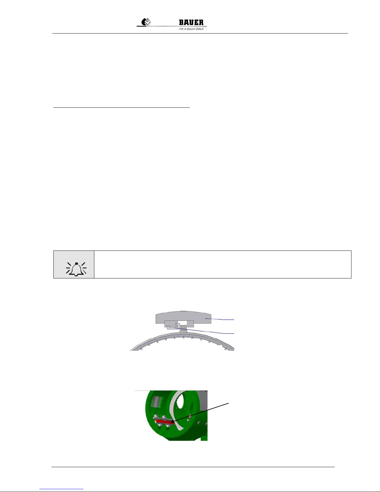
13.1.1 Supply with Sealing Medium
NOTE
It must be ensured that the used sealing media and greases are compatible with
the seals (FPM material). Greases of viscosity class 2 are used as standard, such
as Alvania EP 2 from Shell, Beacon EP 2 from Esso or Aralub HLP 2 from Aral.
On a separator in operation, it is important to supply sealing medium to the blocking seal in the attached unit
against the inflow housing in order to protect the seals in
the attached unit from the medium being separated.
This can be accomplished with sealing grease.
For this purpose, a grease
press must be used every
250 operating hours or
every 2 weeks to introduce
roughly 3 to 5 cm3 of
grease via the lubricating
nipple.
The grease should be supplied while the machine is
running to ensure that the entire seal area is filled with
sealing medium. Lubricate the other lubricating nipples
on the geared motor 1x per year.
To safeguard the function of the seal, check the inspection opening on the bottom of the flange. If sealing medium, water or foreign substances escape here, the
blocking seal is damaged or worn and must be replaced.
If the blocking seal is not replaced, the supply medium
can clog the inspection window over time and also damage the second seal, allowing the medium to damage
the bearing and/or the gearbox. It is therefore very important to regularly check the inspection opening on the
bottom of the flange. No medium should escape from
this opening; otherwise, the blocking seal is damaged
and must be replaced.
Fig. 13-1 Supply with
sealing medium
Inspection
opening
Lubricating
nipple
Fig. 13-2 Lubricating nipple
Fig.13-3 Inspection opening
Fig. 13-2 Lubricating nipple
Page 27
Operating Manual for Bauer Separator Compact
25
13.2 INSPECTION OF THE SIEVE AND THE GUIDE RAILS
The screen and the guide rails must generally be inspected every 1 to 3 months depending on the
separation medium.
For this inspection, the screen must be removed, cleaned with a high-pressure cleaner and then
checked for damage and traces of wear. The plastic profiles of the guide rails visible in the housing
must also be checked for an even contact pattern and good seating. Defective profiles can cause
damage to the screen.
When the screen basket is replaced, the plastic profiles should also be replaced with new ones.
To remove the screen and auger, do as follows:
1. Switch off the feed pump or stop the supply flow.
2. Remove the weights from the output regulator; open the flaps of the output regulator.
3. Allow the separator to run until no more liquid or solid material emerges.
4. Switch off the separator and the main switch on the switch cabinet, then secure the main switch
against reactivation (e.g. with a padlock).
5. Remove the bolt (internal brace) in the head of the auger. The length of the bolt is always the
same as the length of the auger. Remove the mouthpiece by unscrewing the 6 nuts that hold it
in place.
6. Loosen the lock nuts of the scraping bolts and turn the scraping bolts roughly one turn counter-
clockwise, see Fig. 13-13.
7. Remove the rest of the solid cake. You can use a large screwdriver for this. If the cake is very
hard, use a high-pressure cleaner to soften up the cake in order to pull out the auger and
screen.
8. Pull out the screen, or, if it is difficult to separate the screen and auger because solid matter is
jamming the screen and auger, wash out generously with water. This will loosen the screen.
WARNING!
Never pound on the screen or the auger to loosen them as these are precision
components that must be handled with care.
The screen guide rails are situated inside the housing of the separator.
A plastic profile rail (G-rail) is inserted in the screen guide rails.
G-rail
Screen guide rail
G-rail
Fig. 13-4 G-rail
Fig. 13-5 Housing of the Separator Compact with
screen guide rails and G-rail plastic profiles
Page 28

26
Operating Manual for Bauer Separator Compact
S
The plastic profile rails serve to dampen the impact shocks of the separator on the screen guide rails
and reduce friction.
The screen “floats” [“breathes”] in the guide rails, depending on how hard the solid cake is. The slight
up and down movement of the output regulator lever arms are an indication of the “floating” of the
screen in the separator housing.
Inspect both the screen and the plastic profile rails inserted into the guide rails for any wear. If uneven
wear is discernible on the plastic profile rails, these must be replaced with new ones. When inserting a
new screen, the plastic profile rails must naturally also be replaced.
Solid matter in the area of the guide rails must be washed out.
WARNING!
Never loosen the fastening bolts of the screen guide rails on the housing as these
are precision components that must be handled with care.
The screen guide rails are aligned during assembly of the separator using a special template then fixed in place with the fastening
bolts and should not be loosened again. However, if the setting is
changed due to an error, they must be realigned. You can obtain
the required alignment template along with instructions from your
nearest BAUER dealer.
Follow the instruction in sections 6 and 7 to restart the machine.
Also clean the area in which the wear ring sits. This is located at
the rear of the housing at the transition to the inflow area and is
affixed to the housing with 6 bolts. This ring protects the housing
from wear as the screen “breathes” during operation. The wear ring
should be replaced no later than after radial wear of approx. 1 mm
(when the inner diameter of the wear ring is approx. 263 mm) in
order to prevent screen damage.
To do this, remove the 6 bolts located inside on the wear ring. Pull
the wear ring out of the screen housing and replace it with a new
one.
Fig. 13-6 Fastening bolts
Fig. 13-7 Wear ring
Page 29
Operating Manual for Bauer Separator Compact
27
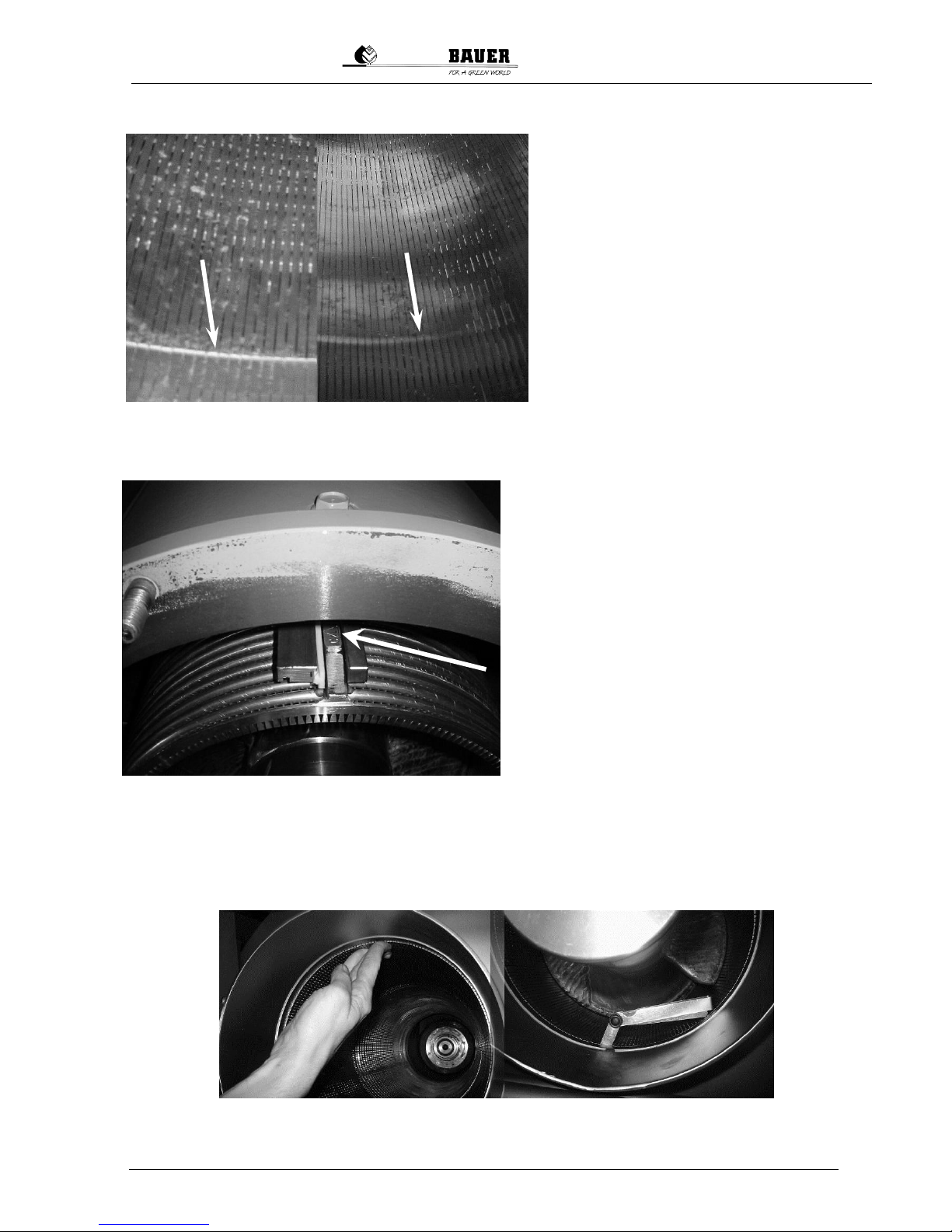
13.3 INSPECTING AND REINSTALLING THE SCREEN
The wearing of the screen occurs primarily in
the area where the auger blades end in the
screen, i.e. at the transition to the pressing
area of the separator. If a sharp-edged transition can be seen in this area (Fig. 13-8 left),
the screen was not installed again correctly
after the previous inspection. In this case, the
screen was damaged due to insufficient floating capacity.
When you reinstall the screen, make sure that
the triangle stamped into the guide rod of the
screen is “up” [12 o’clock position], see also
Fig. 13-9. If this original installation position is
retained, it is possible to identify the causes
for any uneven wear on the basis of wear
marks.
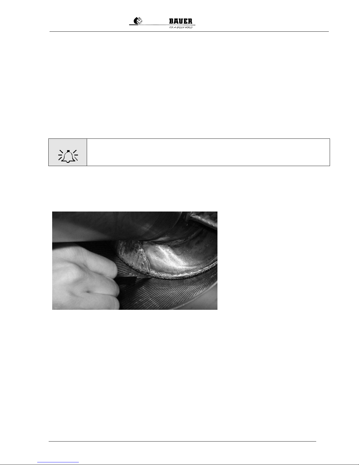
The screen must have sufficient floating capacity after reinstallation; in other words, it must not be under axial tension from the housing and the mouthpiece. If installed correctly, the screen can be moved
somewhat by hand. A small gap of several tenths of a millimeter must exist between the mouthpiece
and the screen. This must be checked with a thickness gage (Fig. 13-10).
Fig.13-8 Wear in the screen due
to screen under tension (left)
Normal screen wear (right)
Inspection of the floating capacity with the
thickness gage
Fig. 13-10 Movable screen in the separator,
inspection of the floating capacity by hand
(left)
Fig.13-9 Sieve installation position, stamped triangle at top and
toward the front of the separator
Page 30

28
Operating Manual for Bauer Separator Compact
S
13.4 INSPECTING AND REINSTALLING THE AUGER
The auger is made of stainless steel. In the area of the screen, the auger blades have been plated with
a special material according to a special process, see Fig. 13-11.
Inspect the auger for any damage and
clean it. The axial contact surface of
the auger mount shown in Fig. 13-11
and the feather key grooves must be
free of solid matter and must not exhibit any damage or markings; otherwise the auger will rotate out of true,
thereby damaging the screen.
If both the auger and the screen are in
good condition [see the following section for the criteria to evaluate the auger and the screen], the auger can be
installed.
Fig. 13-11 Auger plated with special material and hub mount,
new condition
Insert the auger carefully into the separator without striking the feather keys against the axial contact
surface of the auger. This could cause the auger to exhibit axial eccentricity. Turn the auger until the
feather keys snap into the feather key grooves of the auger. Then press the auger upward and screw it
to the auger bolt again (tightening torque 200 Nm).
Check the auger again for axial eccentricity. This
should be less than 1 mm, otherwise the screen will be
damaged. Fig. 13-12 shows the axial eccentricity
check at the factory. If the axial eccentricity is larger,
inspect the auger and fastening elements again for
damage, marks and soiling.
Fig. 13-12 Inspection of the screw axial eccentricity
Then readjust the scraping bolts. To do this,
loosen the lock nuts and slowly adjust the
scraping bolts while turning the auger until the
bolts scrape against the auger. Then turn the
bolts back approx. 30° and lock the lock nuts.
The scraping bolts must be readjusted every 4
weeks.
Fig. 13-13 Scraping bolts
Page 31
Operating Manual for Bauer Separator Compact
29
Fig. 13-14 Measuring of the working gap between the screen and the auger;
the gap is measured on the bottom side of the screen while the machine is at
rest. The measurement yields two times the working width because the screen
rests on the top of the auger when the machine is nut running.
13.5 EVALUATION CRITERIA FOR THE AUGER AND SCREEN WITH REGARD TO WEAR
AND RECOATING
All moving parts on the separator are subject to some amount of wear. Some of the parts that are directly subject to wear and must therefore be inspected regularly have already been described. Good
regular inspections and maintenance of the wearing parts will significantly lengthen the service life of
the parts. Worn parts should be replaced as quickly as possible in order to avoid the damage that
might otherwise result.
The parts that directly influence the operation of the separator are the screen and the auger. Independent of this, the “normal” operating condition of the separator is also influenced by parameters other than wear.
In principle, only the auger can be recoated to be used again; the screen cannot be recoated.
In order to ensure the necessary quality and precision, the recoating of the auger may only be performed by a workshop authorized by BAUER.
WARNING
Never hire another shop to recoat the auger for you since incorrect performance
and failure to observe the necessary tolerances could destroy the screen and void
all warranty claims (see Fig. 13-8 Screen wear).
The normal wear of the screen can be observed as an increase in the inner diameter and the screen
gap width. The wear of the screen and the auger generally affects the proper functioning of the separator and can be identified based on reduced throughput and worse drainage of the liquid phase. However, when observing such changes, it must also be ruled out that the supply medium and its consistency have changed.
Wearing of the screen or of the auger on
the outer edges of the blade changes the
working gap. In new condition, the working
gap and therefore the radial gap between
the screen and the auger (initial gap width)
is approx. 0.2 - 0.4 mm; this can be measured with a thickness gage (Fig. 13-14).
If the radial gap between the screen and
the auger becomes twice the initial gap
width or larger, this influences not only the
operating condition but also poses the risk
that the screen could be damaged or even
split. If the radial gap between the screen
and the auger is still larger than two times
the original gap width even after replacing
the screen, the auger must be recoated.
The most important criterion for the wear of the screen and the auger is however the operating condition of the machine; in other words, if the result no longer satisfies the requirements (throughput, liquid
phase, etc.), the screen must be replaced and/or the auger recoated
Additional indications for the need to recoat the auger can be found in the appearance of the plating
material as shown below in Fig. 13-15.
In principle, the auger should be recoated before the plating has been removed by wear, uncovering
the base material of the auger. Otherwise, the wear on the auger will increase severely enough that it
can no longer be recoated at reasonable expense.
Page 32
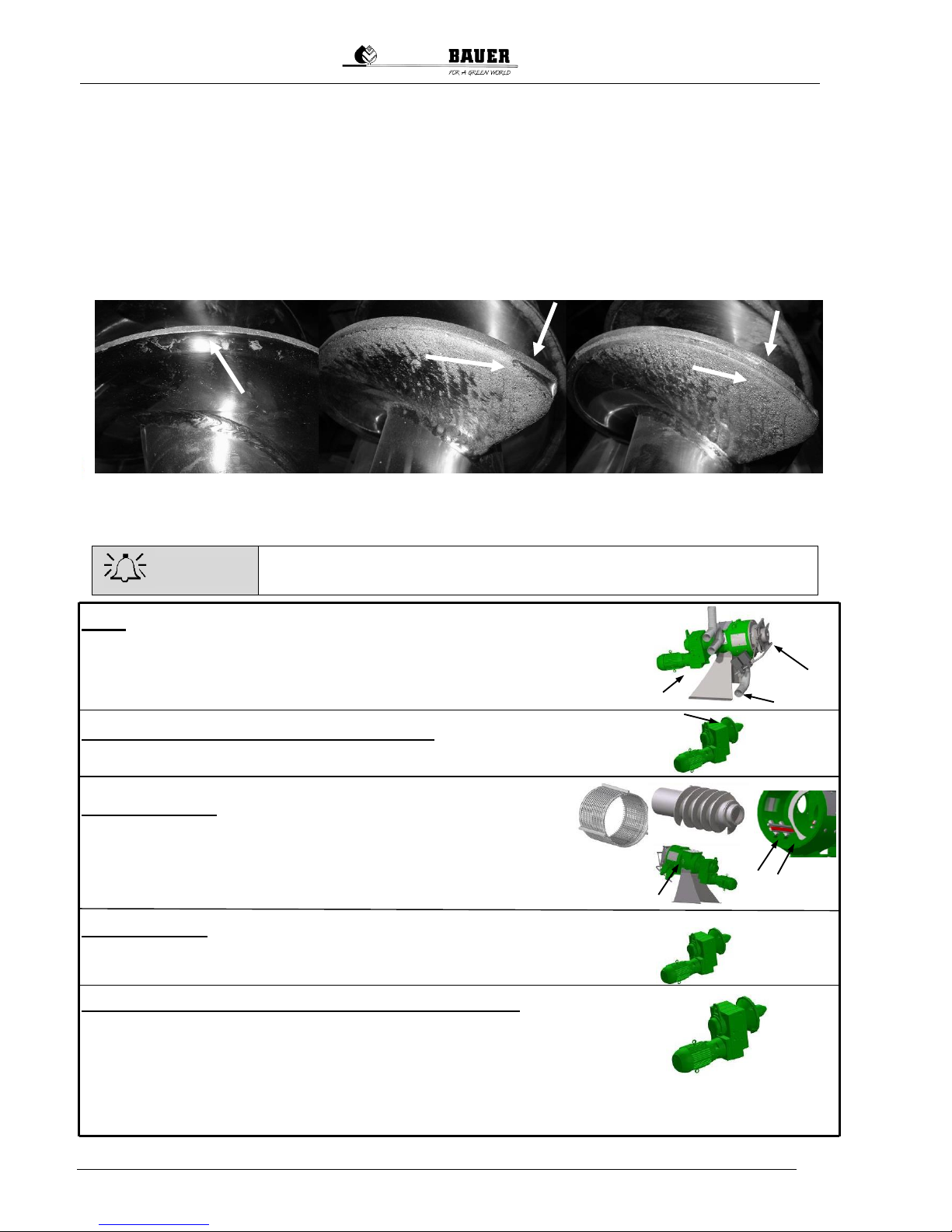
30
Operating Manual for Bauer Separator Compact
S
For example, Fig. 13-15, right and middle images, shows plating that has been worn down on the outer
edges of the auger, but recoating is still possible because the plating on the face side is still retained
up to 20%, meaning that the actual auger blade has not yet been damaged. Excluding the plating, the
auger blades have a thickness in this area of 10 mm, meaning that the remaining plating can be determined very precisely with a depth caliper.
The left image in Fig. 13-15 shows a auger on which the axial plating has been worn down completely
on the outer edges of the auger blade. In addition, the auger thickness itself has been reduced almost
to half. A cost-effective recoating is not possible in this case since the base stiffness of the auger blade
would no longer suffice for sufficient bonding of the plating. A new auger is therefore required.
13.6 SUMMARY OF MAINTENANCE AND INSPECTION INTERVALS
Check the operational safety of the machine before every start !
Daily:
Visual inspection of the solid cake and the effluent
Visual inspection of the machine and gearbox seals (see section
13.1.1 Fig. 13-3 Gearbox inspection opening)
Every 250 operating hours (or every 2 weeks):
Supply with sealing medium (see section 13.1.1)
Every 1-3 months
Inspection and cleaning of the housing, screen, guide rails,
plastic profile rails, auger, housing protection ring
(see section 13.2 - 13.5)
Readjust scraping bolts (see section 13.3 Fig. 13-13)
Every 6 months:
Check gearbox oil level
After 10,000 operating hours (no later than every 2 years)
Geared motor oil change (see the gearbox and motor documentation for
oil quantity and type)
Inspect the bearing (see the gearbox and motor documentation for de-
tails)
Fig. 13-15 Indications of the need for refurbishing the screw
WARNING
Page 33

Operating Manual for Bauer Separator Compact
31
14 PROBLEMS - TROUBLESHOOTING
WARNING
Troubleshooting should only be performed by appropriately qualified personnel.
It is very important for you to familiarize yourself with the “normal” operating condition of the separator
during your application. “Normal” includes the discharge speed in direct connection with the desired
DM content of the solid cake. The DM content can be adjusted via the position and number of weights
on the lever arm of the output regulator. You will need to incrementally vary the settings to determine
the optimal and for you “normal” operating condition. It is also necessary to adjust the pump throughput
in order to determine the optimal capacity utilization of the separator for the “normal” condition. The
effluent discharge and throughput represents another factor that can be evaluated.
However, since the consistency of the supply medium can change over time, you must expect that the
“normal” operating condition of the machine in your application will also change.
If major changes with respect to the “normal” operating condition occur over a prolonged period of
time, it is important to determine the precise cause. The search for possible sources of error is simpler
when the principle and functioning of the BAUER separator are sufficiently well understood.
14.1 PRINCIPLES OF A “NORMAL” OPERATING CONDITION
The auger of the separator has a defined diameter over its length and is adapted to the screen cylinder. The auger and screen diameters are very precisely adapted to each other, and this relationship
must be maintained to ensure optimal operation of the separator.
The open drainage of the influent takes place in the inflow area of the screen; in other words, the water
not bound up in solid matter via capillary action is removed. In the press area, where the solid cake
forms, water bound up via capillary action is pressed out. If the influent contains no solid matter, no
solid cake is formed as well as no transport or continuous discharging of the cake. In principle: the
higher and more uniform the incoming concentration of solid matter, the larger the discharge speed of
the solid cake from the mouth piece.
The uniformity of the influent directly determines the discharge speed of the solid cake. To achieve
sufficient homogenization and uniformity of the solid matter in the liquid, it is necessary to use a stirrer
that is adapted to the throughput and situated in the inflow tank before supply of the medium to the
separator. The use of a bypass or overflow line at the inflow element of the separator helps ensure that
the separator only receives the optimal volume of medium for the process without producing excess
pressure in the separator. The solid cake formed in the separator produces a self-cleaning process for
the screen, thereby ensuring optimal operation of the separator.
This self-cleaning effect of the screen is significantly influenced by the working gap between the
screen and the auger. Wear on the screen or on the outer edges of the auger blade can change this
working gap and negatively impact the self-cleaning process as well as the “normal” operation of the
separator.
Indications of possible deviations from the “normal operating condition” of the separator as well as possible causes and remedies are provided in the following table to assist you in troubleshooting problems.
Page 34
32
Operating Manual for Bauer Separator Compact
S
14.2 TROUBLESHOOTING
Fault
Cause
Remedy
No solids are produced
No liquid is discharged
Separator is running
1. The material supply has been interrupted:
The pump is off
Inflow element or ventilation open-
ing blocked; a siphon effect occurs [“overflow line is completely
filled”]; the outlet of the overflow
line is submersed in the liquid.
Clogged / restricted effluent line
2. The auger is turning clockwise.
3. The rotation direction of the pump
is incorrect, the supply line is vibrating
4. Long fibers (hey, stray, etc.) are
blocking the liquid transport
1. Check: Switch cabinet and overflow
line.
Inspect and start the pump.
Clean the lines. Install a ventilation
pipe with a larger cross-section; reduce the pump capacity; ensure
that the overflow line is clear.
Ensure that the liquid can drain
freely.
2. Swap the two phases of the electricity line so that the auger turns
counterclockwise.
3. Change the rotation direction of the
pump.
4. Replace the cutting blade in the
pump cutting unit.
Solid discharge too low
Effluent discharge too low
(lower than is typical for this
medium)
Separator is running
1. Pump capacity (feed rate) is too
low – no overflow in the bypass
line
2. Lifting effect in the overflow line,
the medium is being drawn out of
the separator
3. Too many weights in place or too
much contact pressure
4. Excess wear on the screen or auger
5. screen positioned incorrectly or
clogged;
6. auger channels clogged
7. screen only worn in certain places,
guide rails for the screen not set
correctly
8. Slurry is pumped / stirred too much
(ground fine)
1. Inspect pump (rotation direction)
and/or control the pump capacity.
Check the transport line.
2. Affix the ventilation valve / pipe to
the inflow of the separator.
Reduce the feed rate so that the
overflow pipe is no more than half
full. Ensure that the overflow can
flow out freely.
3. Remove two weights or reduce the
leverage of the weights.
4. Check the auger diameter, check
the screen for wear. Replace the
screen and auger, if necessary.
5. Clean the screen through the side
windows or remove it for cleaning, if
necessary.
6. Clean the auger, contact the BAUER company concerning possible
changes to the inflow of the separator.
7. Check the guide rails for soiling /
clogging.
8. Install a buffer container at the
inflow.
Solid discharge is very low
Effluent discharge is normal
Separator is running
1. The solid portion in the inflow is
very low
2. The gap width of the screen is too
large
1. Add some solid to the inflow.
2. Install a screen with a smaller gap
width. The available screen gap
widths are: 0.25, 0.35, 0.50, 0.75,
and 1.0 mm. After changing the
gap width, accustom yourself to a
change in the “normal” operating
condition.
Page 35

Operating Manual for Bauer Separator Compact
33
Fault
Cause
Remedy
Solid cake is very hard;
Solid matter comes out slowly
and very dry
Separator is running
The amperemeter indicates
higher values than usual
1. Too many weights or the leverage
is too great, meaning that the contact pressure of the output regulator is too high.
2. The supply medium has changed
or the supply line has been
changed.
1. Reduce the number of weights or
the leverage; if the contact force is
too high, the screen could be destroyed.
2. Check the consistency of the supply medium and check the supply
line for any blockages.
No discharging of solids
Minimal discharging of liquid
1. Rotation direction of the separator
reversed
2. Auger channels clogged
1. Check the electrical connection
2. Check and clean the auger
Increased auger and screen
wear
Abrasive components in the medium,
such as sand
If possible, allow the abrasive components to settle before separation.
Moisture content of the discharged solid varies greatly
The separated medium (slurry) has
varying consistency
Mix and homogenize the medium (slurry) thoroughly.
Geared motor of the separator
switches off
The motor switches off when the
permissible power consumption of
the motor has been exceeded.
The setting for the maximum power
consumption applies to operation
under load
1. Overload
2. Power consumption is too high
because the solid cake is too hard.
3. The setting for the maximum power consumption is not configured
correctly or the control unit has
been damaged.
4. Foreign bodies are blocking the
auger
1. Check the motor protection for
correct setting; set to maximum
value, if necessary.
2. See configuration instructions in
the section Initial Startup.
3. Have the shut-off limit adjusted
again by a qualified electrician according to the instructions in the
switch cabinet circuit diagram.
4. Check the inflow to the separator
and remove any foreign bodies;
check the auger and screen.
Cake ejection – The cake
has been pushed out
The solid cake breaks up and
liquid emerges from the mouthpiece
1. Not enough weights or the leverage of the weights is too low.
2. The pump pressure is too high; the
optimal pressure / operation for the
separator is 2 m water column with
a steady feed rate.
3. The incoming concentration of
solids fluctuates greatly. The separated medium has too little solid
content
4. Solids are too fine and have no
fibrous structure
1. Add additional weights or increase
the leverage of the weights (important: never more than two
weights per lever arm).
2. Reduce the pump pressure by
lowering the pump capacity or replacing the pump.
3. Thoroughly mix and homogenize
the medium (slurry) to produce a
uniform solid cake speed. See
configuration instructions in the
section Initial Startup.
The cake may be ejected if the solid content in the supply medium
decreases significantly.
4. Use a finer screen.
Page 36

34
Operating Manual for Bauer Separator Compact
S
Fault
Cause
Remedy
Replacement of the blocking seal
Despite the supply of sealing
medium (see section Mainte-
nance and Inspection under
Supply with Sealing Medium),
liquid and sealing medium is
discharged from the inspection opening on the bottom of
the flange.
1. The pump is a high-pressure pump
and/or the supply medium is highly
abrading.
2. The blocking seal has been worn
out by the duration of operation.
1. Replace the pump with a lowpressure pump.
2. The blocking seal must be replaced before the second seal is
damaged, which would lead to
damage to the bearing or the
geared motor.
Problems that cannot be corrected
A problem as described above
cannot be corrected despite
optimal configuration according
to the instructions given above.
Document the symptoms and the
measures you have taken to correct the
problem.
Contact your dealer or the BAUER
company.
Page 37

Operating Manual for Bauer Separator Compact
35
15 ACCESSORIES
15.1 SEPARATOR CONTROL
DANGER
The connection of the switch cabinet to the electrical supply and the connection
of the separator motor to the switch cabinet must be performed by an electrical
expert. The cable dimensions and the preliminary fuse must correspond to the
power specifications.
The BAUER separator is generally delivered with an electrical switch cabinet that was designed for precisely your application (option).
Normally, the switch cabinet has additional connections, e.g. for the feed pump, the fill level sensor,
etc., which are controlled by the switch cabinet or which control the operation of the separator. The circuit diagrams contained in the switch cabinet explain the individual electrical connections, the cabling
and the circuits. Your electrician requires these circuit diagrams to connect the separator to the switch
cabinet and your local power supply.
Every part and every component in the switch cabinet is numbered and listed in the parts list for the
switch cabinet, which is appended to the circuit diagrams in the switch cabinet. Additional information
required for ordering replacement parts, such as the manufacturer, can be determined based on these
article numbers.
WARNING
The correct installation of the switch cabinet is absolutely essential for faultless operation. It is also absolutely essential that the operating personnel are familiar with the various settings on the switch cabinet.
15.1.1 Motor protection circuit breaker F1
Factory setting: 6.5 A
WARNING
Never set a value higher than
6.5 A
Fig .15-1 Switch cabinet
Fig. 15-2 Control
Fig. 15-3 Motor protection circuit breaker F1
Page 38

36
Operating Manual for Bauer Separator Compact
S
16 NOTES
Page 39
Operating Manual for Bauer Separator Compact
37
17 CONFORMITY DECLARATION
EC Conformity Declaration
according to EC Directive 2006/42/EC
The manufacturer
BAUER Gesellschaft m.b.H.
Kowaldstrasse 2, 8570 Voitsberg, Austria
Tel.: +43 3142 200 -0; Fax: +43 3142 200 -320/-340
declares that the machine specified below
Machine designation BAUER Separator
Machine type / base device Compact
appropriately satisfies the applicable provisions of the Machinery Directive 2006/42/EC.
This declaration becomes void in event of any changes to the machine made without the approval of BAUER
GmbH.
The following standards in the current versions were applied:
DIN EN ISO 12100-1 Safety of machinery - Basic concepts, general principles for design - Part 1:
Basic terminology, methodology
DIN EN ISO 12100-2 Safety of machinery - Basic concepts, general principles for design - Part 2:
Technical principles
DIN EN 60204-1 Safety of machinery - Electrical equipment of machines, General requirements
EN ISO 14121-1 Safety of machinery – Risk assessment principles
DIN EN 809 Pumps and pump units for liquids, Common safety requirements
The documents associated with the machine according to Appendix VII Part B have been enclosed.
The incomplete machine may only be put into operation when it has been determined that the machine into which the incomplete machine should be installed satisfies the provisions of the Machinery
Directive (2006/42/EC). The CE mark is applied by the operator as the final manufacturer.
Party responsible for documentation: Thomas Theissl, Kowaldstraße 2, 8570 Voitsberg, Austria
_______________________________
Designer Responsible for the Product
Marktschorgast, 17-Jun-2011
Commercial Management
 Loading...