

Page 1
Instruction Manual and Replacement Parts List
Mini Verticus
High Pressure Gas Compressor Units
G 120 II V
April 4, 2013 1st Edition, Rev. 0 Chg. 2 MNL-126509
© Bauer Compressors, Inc.
BAUER Compressors, Inc. Phone: (757) 855-6006
1328 Azalea Garden Road Fax: (757) 855-6224
Norfolk, Virginia 23502-1944 www.bauercomp.com
Page 2
G 120 II V
This information is believed to be accurate by Bauer Compressors, Inc., as of it’s date of publication, but
Bauer offers NO WARRANTY regarding the accuracy, or continuing accuracy, of the information set forth
herein. Bauer shall not be liable for inaccuracies in, or consequences resulting from, your use of this information. All information supplied is in connection with sales of Bauer’s products, and is thus subject to
Bauer’s standard terms and conditions of sale. Bauer reserves the right to change this information and has
no obligation to update these materials. This information is copyrighted by Bauer Compressors, Inc., and
Bauer reserves to itself all rights to this publication. Bauer’s customers have no right to reproduce, rewrite,
modify, license or permit anyone else’s use of this information, without the express written permission of
Bauer Compressors, Inc.
^ WARNING
This Instruction Manual and Replacement Parts List contains safety information and instructions
for the G 120 II V High Pressure Gas Compressor Units.
You must read, understand and follow all safety precautions and instructions.
1st Edition August 30, 2011
Rev Chg Date Notes Auth
0 1 Nov. 8, 2011 Added 50 Hz model SS
0 2 Apr. 4, 2013 Updated Block P/N’s SS
Page i 1st Edition, Rev. 0 Chg. 2
Page 3

MNL-126509
Table of Contents
CHAPTER 1:- - - - - - - - - - - - - - - - - - - - - INTRODUCTION
1.1 HOW TO USE THIS MANUAL.........................................................................................................................................1
1.1.1 Manual Safety Notices .......................................................................................................................................................1
1.2 HOW TO USE THE REPLACEMENT PARTS LIST....................................................................................................2
1.3 HOW TO USE THE APPENDIX.......................................................................................................................................3
1.4 UNIT SPECIFICATIONS ..................................................................................................................................................4
1.4.0.1 Compressor Drive ..........................................................................................................................................................4
1.4.0.2 Purification System Applicability ..................................................................................................................................4
1.4.0.3 Pressure Switch Settings.................................................................................................................................................4
1.4.0.3.1 Inlet Pressure Switch Settings ........................................................................................................................................4
1.4.0.3.2 Final Pressure Switch Setting ......................................................................................................................................... 4
CHAPTER 2:- - - -OPERATING INSTRUCTIONS; MAPLE SYSTEM
2.1 DESCRIPTION.................................................................................................................................................................... 5
2.1.1 Emergency Stop Button .....................................................................................................................................................5
2.1.2 Operator Interface ..............................................................................................................................................................6
2.1.2.1 Run Screen...................................................................................................................................................................... 6
2.1.2.2 Main Menu Screen.......................................................................................................................................................... 7
2.1.2.2.1 Run..................................................................................................................................................................................7
2.1.2.2.2 Alarms History................................................................................................................................................................8
2.1.2.2.3 Status .............................................................................................................................................................................. 8
2.1.2.2.4 Contact............................................................................................................................................................................8
2.1.2.2.5 Login............................................................................................................................................................................... 8
2.1.2.2.6 Configuration..................................................................................................................................................................9
2.1.2.2.7 Parameters.....................................................................................................................................................................10
2.1.2.2.8 Tools .............................................................................................................................................................................10
2.2 STARTING AND STOPPING UNIT...............................................................................................................................10
2.2.1 Before Starting. ................................................................................................................................................................ 10
2.2.2 To Start Unit.....................................................................................................................................................................11
2.2.3 To Stop Unit. .................................................................................................................................................................... 11
2.3 SCREEN FLOW................................................................................................................................................................14
CHAPTER 3:- - - - - - - - - - - - - - - - - - - - - - IK120 II C & G
3.1 MAINTENANCE AND PARTS.......................................................................................................................................15
3.1.1 Description ....................................................................................................................................................................... 15
3.1.2 Component Location ........................................................................................................................................................15
3.1.3 Air Flow Diagram ............................................................................................................................................................ 16
3.1.4 Compressor Lubrication................................................................................................................................................... 17
3.1.4.1 Description....................................................................................................................................................................17
3.1.4.2 Oil Level Check............................................................................................................................................................17
3.1.4.3 Oil Change Interval.......................................................................................................................................................18
3.1.4.4 Oil Change.................................................................................................................................................................... 19
3.1.5 Venting the Oil Pump.......................................................................................................................................................19
3.1.5.1 Gas Intake System ........................................................................................................................................................ 19
April 4, 2013 Page ii
Page 4

G 120 II V
3.1.6 Inter-stage Separator.........................................................................................................................................................20
3.1.6.1 Maintenance..................................................................................................................................................................21
3.1.7 Cooling .............................................................................................................................................................................21
3.1.7.1 General..........................................................................................................................................................................21
3.1.8 Valves and Heads .............................................................................................................................................................21
3.1.8.1 Functional Description..................................................................................................................................................21
3.1.8.2 General Instructions for Changing the Valves..............................................................................................................22
3.1.8.3 Changing the IK120 II C & G, 1st Stage Valve ...........................................................................................................23
3.1.8.4 Removing the IK120 II C & G, 2nd Stage Valves. ......................................................................................................24
3.1.8.5 Reassembling the Valves of the 2nd Stage. ..................................................................................................................25
3.1.8.6 Removing the IK120 II C & G, 3rd Stage Valves ........................................................................................................26
3.1.8.7 Reassembling the Valves of the 3rd Stage....................................................................................................................27
3.1.9 Replacement Parts List.....................................................................................................................................................28
3.1.10 Troubleshooting and Repair .............................................................................................................................................47
3.1.10.1 Troubleshooting Table ..................................................................................................................................................47
3.1.10.2 Repair Instructions ........................................................................................................................................................48
3.2 THREE STAGE AUTOMATIC CONDENSATE DRAIN SYSTEM...........................................................................49
3.2.1 Description .......................................................................................................................................................................49
3.2.1.1 Normal Operation .........................................................................................................................................................50
3.2.1.2 Condensate Drain..........................................................................................................................................................50
3.2.1.3 Start Unloading .............................................................................................................................................................50
3.2.1.4 Standstill Drainage........................................................................................................................................................51
3.2.2 Component Description....................................................................................................................................................51
3.2.2.1 Condensate Drain Piping ..............................................................................................................................................51
3.2.2.2 Electrical Connection....................................................................................................................................................51
3.2.3 ACD Maintenance............................................................................................................................................................51
3.2.4 ACD Replacement Parts List............................................................................................................................................52
3.3 CONDENSATE COLLECTOR .......................................................................................................................................54
3.3.1 Condensate Collector Replacement Parts List .................................................................................................................55
CHAPTER 4:- - - - - - - - - - - - - - - - -PURIFICATION SYSTEM
4.1 INTRODUCTION..............................................................................................................................................................56
4.1.1 General Purification System Procedures..........................................................................................................................56
4.1.2 Chamber Safety Bore .......................................................................................................................................................56
4.1.3 Manual Condensate Drainage...........................................................................................................................................57
4.1.4 Model, Serial Number and Part Number Identification ...................................................................................................57
4.1.4.1 Compressor Dataplate...................................................................................................................................................57
4.1.4.2 Purification System Dataplate ......................................................................................................................................58
4.1.4.3 Cartridge Installation Dataplate ....................................................................................................................................58
4.1.5 Breathing Air Purification System Configurations ..........................................................................................................58
4.1.6 Industrial Purification System Configurations .................................................................................................................59
4.1.7 Cartridge Operating Life ..................................................................................................................................................59
4.1.7.1 Calculating the Maximum Cartridge Operating Hours.................................................................................................60
4.1.7.2 Calculating the Adjusted Cartridge Operating Hours...................................................................................................60
4.1.7.3 Air Purification Cartridge Operating Hours Form........................................................................................................62
4.2 P1 PURIFICATION SYSTEM.........................................................................................................................................63
4.2.1 Major Components ...........................................................................................................................................................63
4.2.2 Component Description....................................................................................................................................................64
4.2.2.1 Oil & Water (condensate) Separator.............................................................................................................................64
4.2.2.2 Chamber........................................................................................................................................................................65
Page iii 1st Edition, Rev. 0 Chg. 2
Page 5

MNL-126509
4.2.2.3 Cartridge .......................................................................................................................................................................65
4.2.2.4 Cartridge Handling ....................................................................................................................................................... 65
4.2.2.5 Condensate Drain Valve...............................................................................................................................................65
4.2.2.6 Check Valves................................................................................................................................................................ 65
4.2.2.7 Bleed Valve .................................................................................................................................................................. 66
4.2.2.8 Pressure Maintaining Valve..........................................................................................................................................66
4.2.2.9 Safety Valve..................................................................................................................................................................66
4.3 MAINTENANCE............................................................................................................................................................... 66
4.3.1 Oil and Water Separator...................................................................................................................................................66
4.3.2 Cartridge Replacement.....................................................................................................................................................67
4.3.2.1 Leaking at the Safety Bore ...........................................................................................................................................68
4.4 REPLACEMENT PARTS LIST......................................................................................................................................69
CHAPTER 5:- - - - - - - - - - - - COMPRESSOR DRIVE; G 120 II V
5.1 VERTICAL COMPRESSOR DRIVE.............................................................................................................................. 72
5.2 MAINTENANCE OF THE V-BELT AND SHEAVES.................................................................................................. 72
5.2.1 Check The Sheaves. ......................................................................................................................................................... 72
5.2.2 Check the V-belt...............................................................................................................................................................72
5.3 REPLACEMENT PART LIST ........................................................................................................................................73
CHAPTER 6:- - - - - - - - - - ELECTRICAL PANEL, ASY-1058 XL
6.1 OVERVIEW.......................................................................................................................................................................75
6.2 ELECTRICAL PANEL ....................................................................................................................................................75
6.2.1 Wiring Diagram................................................................................................................................................................76
6.2.2 Electrical Panel Interior Access .......................................................................................................................................76
6.2.3 Optional Equipment .........................................................................................................................................................76
6.3 AC POWER REQUIREMENTS...................................................................................................................................... 76
6.4 ELECTRICAL PANEL COMPONENTS....................................................................................................................... 77
6.4.1 Programable Logic Controller (PLC)...............................................................................................................................77
6.4.2 Replacing the PLC ...........................................................................................................................................................78
6.4.3 Installing a New Program.................................................................................................................................................78
6.4.4 Installing an EEPROM.....................................................................................................................................................78
6.4.5 Hourmeter.........................................................................................................................................................................79
6.4.6 Transformer and Fuses .....................................................................................................................................................79
6.4.7 Motor Starter. ................................................................................................................................................................... 80
6.4.8 Overload Relay................................................................................................................................................................. 80
6.4.9 Starter Reset .....................................................................................................................................................................80
6.4.10 Power Supply ................................................................................................................................................................... 81
6.5 ALARMS............................................................................................................................................................................81
6.5.1 Final Separator Warning ..................................................................................................................................................81
6.5.2 Securus
6.5.2.1 Securus® Cartridge ...................................................................................................................................................... 82
6.5.2.2 Securus II
6.5.3 Compressor High Temperature ........................................................................................................................................ 83
6.5.4 Compressor Low Oil Pressure..........................................................................................................................................83
6.5.5 Compressor Overrun Timer .............................................................................................................................................83
6.5.6 Condensate Fault ..............................................................................................................................................................83
6.5.7 Motor Starter Overload Trip ............................................................................................................................................84
®
Electronic Moisture Monitor System................................................................................................................82
®
Transmitter.................................................................................................................................................82
April 4, 2013 Page iv
Page 6

G 120 II V
6.6 PLC INPUTS AND OUTPUTS ........................................................................................................................................84
6.6.1 Analog Inputs to the PLC.................................................................................................................................................85
6.7 WIRING HARNESS LAYOUT .......................................................................................................................................86
6.8 REPLACEMENT PARTS LIST ......................................................................................................................................88
6.9 PARTS LIST FOR MODELS WITH A 5 HORSEPOWER MOTOR.........................................................................96
6.10 PARTS LIST FOR MODELS WITH A 7½ HORSEPOWER MOTOR......................................................................97
6.11 PARTS LIST FOR MODELS WITH A 10 HORSEPOWER MOTOR.......................................................................98
6.12 PARTS LIST FOR MODELS WITH A 15 HORSEPOWER MOTOR.......................................................................99
6.13 PARTS LIST FOR MODELS WITH A 20 HORSEPOWER MOTOR.....................................................................100
CHAPTER 7:- - - - - - - - - - - - - - - - -INDICATORS & VALVES
7.1 DESCRIPTION................................................................................................................................................................101
7.2 REPLACEMENT PARTS LIST ....................................................................................................................................101
7.1 NONADJUSTABLE VALVES .......................................................................................................................................103
7.2 PRESSURE MAINTAINING VALVE...........................................................................................................................103
7.3 SAFETY VALVES...........................................................................................................................................................104
CHAPTER 8:- - - - - - - - - - - - - - - - - - - - - - - - -APPENDIX
8.1 SAFETY............................................................................................................................................................................105
8.1.1 General Safety Precautions.............................................................................................................................................105
8.1.2 Safety Warning Labels ...................................................................................................................................................107
8.2 UNPACKING, HANDLING AND INSTALLATION..................................................................................................108
8.2.1 Unpacking and Handling................................................................................................................................................108
8.2.2 Installation of the Compressor Unit ...............................................................................................................................109
8.2.2.1 General........................................................................................................................................................................109
8.2.2.2 Ventilation ..................................................................................................................................................................110
8.2.2.2.1 Outdoor Installation ....................................................................................................................................................110
8.2.2.2.2 Indoor Installation.......................................................................................................................................................110
8.2.2.2.3 Natural Ventilation .....................................................................................................................................................110
8.2.2.2.4 Forced Ventilation ......................................................................................................................................................111
8.2.3 Intake Air........................................................................................................................................................................111
8.2.3.1 Inside Air Source ........................................................................................................................................................111
8.2.3.2 Outside Air Source......................................................................................................................................................112
8.2.4 Compressor Intake Piping ..............................................................................................................................................112
8.2.5 Installation Procedures ...................................................................................................................................................113
8.2.6 Electrical Installation......................................................................................................................................................113
8.2.6.1 Electric Drive..............................................................................................................................................................113
8.2.6.2 Electrical Supply.........................................................................................................................................................113
8.2.7 Pneumatic Leaks.............................................................................................................................................................115
8.3 LONG TERM STORAGE...............................................................................................................................................116
8.3.1 General ...........................................................................................................................................................................116
8.3.2 Preparations ....................................................................................................................................................................116
8.3.2.1 Units Equipped with a Filter System ..........................................................................................................................116
8.3.3 Preserving the Compressor.............................................................................................................................................116
8.3.4 Preventive Maintenance During Storage........................................................................................................................117
8.3.5 Lubrication Oils for Preservation ...................................................................................................................................117
Page v 1st Edition, Rev. 0 Chg. 2
Page 7

MNL-126509
8.3.6 Reactivating the Compressor Unit .................................................................................................................................117
8.4 REPRODUCIBLE FORMS............................................................................................................................................118
8.4.1 Scheduled Maintenance Form........................................................................................................................................118
8.4.2 Air Purification Cartridge Operating Hours...................................................................................................................121
8.4.3 Record of Operating Hours ............................................................................................................................................122
8.5 REFERENCE DATA.......................................................................................................................................................123
8.5.1 Tightening Torque Values..............................................................................................................................................123
8.5.2 Torque Sequence Diagrams ........................................................................................................................................... 123
8.5.3 Conversion Formulas .....................................................................................................................................................123
8.5.4 Approved Lubricants Chart............................................................................................................................................124
8.5.5 Glossary of Abbreviations and Acronyms .....................................................................................................................124
8.6 ADDITIONAL DOCUMENTS ......................................................................................................................................125
8.6.1 Diagrams and Drawings.................................................................................................................................................125
8.6.2 Other Documents............................................................................................................................................................125
April 4, 2013 Page vi
Page 8

G 120 II V
List of Figures
CHAPTER 1:- - - - - - - - - - - - - - - - - - - - - INTRODUCTION
Figure 1-1 Compressor Identification Label .............................................................................................................................2
CHAPTER 2:- - - - OPERATING INSTRUCTIONS; MAPLE SYSTEM
Figure 2-1 MNR-0053...............................................................................................................................................................5
Figure 2-2 PLC & Battery .........................................................................................................................................................5
Figure 2-3 Maple System; Run Screen......................................................................................................................................6
Figure 2-4 Maple System; Home Screen...................................................................................................................................7
Figure 2-5 Status Screen............................................................................................................................................................8
Figure 2-6 Login Screens ..........................................................................................................................................................9
Figure 2-7 Parameters Screen..................................................................................................................................................10
Figure 2-8 Operator Interface Screen Flow.............................................................................................................................14
CHAPTER 3:- - - - - - - - - - - - - - - - - - - - - - IK120 II C & G
Figure 3-1 IK120 II C & G Compressor Blocks, Front View .................................................................................................15
Figure 3-2 Air Flow Diagram..................................................................................................................................................16
Figure 3-3 Lubrication Oil Circuit ..........................................................................................................................................17
Figure 3-4 Oil Sight Glass.......................................................................................................................................................18
Figure 3-5 Oil Filler Cap .........................................................................................................................................................18
Figure 3-6 Removing the Oil Filter Cover ..............................................................................................................................18
Figure 3-7 Replacing the Oil Filter .........................................................................................................................................18
Figure 3-8 Inter-stage Separator..............................................................................................................................................20
Figure 3-9 Valve Operation.....................................................................................................................................................21
Figure 3-10 IK120II C & G, 1st Stage Valve............................................................................................................................22
Figure 3-11 IK120 II C 1st Stage Valve Head and Plate Valve................................................................................................23
Figure 3-12 IK120 II C & G, 2nd Stage Valve Head and Valves .............................................................................................24
Figure 3-13 Using the Special Valve Tool ................................................................................................................................25
Figure 3-14 Securing the Intake Valve......................................................................................................................................25
Figure 3-15 IK120 II C & G, 3rd Stage Valve Head and Valves..............................................................................................26
Figure 3-16 Removing the 3rd Stage Pressure Valve ...............................................................................................................27
Figure 3-17 Crankcase Assembly..............................................................................................................................................28
Figure 3-18 Piston and Cylinder, 1st Stage...............................................................................................................................30
Figure 3-19 Piston and Cylinder, 2nd Stage..............................................................................................................................31
Figure 3-20 Piston and Cylinder, 3rd Stage ..............................................................................................................................32
Figure 3-21 Piston and Sleeve, 3rd Stage..................................................................................................................................33
Figure 3-22 1st Stage Valve Head and Valve, IK120 II C & G................................................................................................34
Figure 3-23 2nd Stage Valves and Valve Head.........................................................................................................................36
Figure 3-24 3rd Stage Valves and Valve Head .........................................................................................................................38
Figure 3-25 Flywheel ................................................................................................................................................................39
Figure 3-26 Inter-Stage Separator .............................................................................................................................................40
Figure 3-27 Lubrication System Assembly...............................................................................................................................42
Figure 3-28 Cooling System......................................................................................................................................................44
Page vii 1st Edition, Rev. 0 Chg. 2
Page 9

MNL-126509
Figure 3-29 Inlet Assembly....................................................................................................................................................... 46
Figure 3-30 Automatic Condensate Drain ................................................................................................................................49
Figure 3-31 ACD Operation Diagrams .....................................................................................................................................50
Figure 3-32 ACD System..........................................................................................................................................................52
Figure 3-33 ACD Valve and Manifold Assembly ....................................................................................................................53
Figure 3-34 Condensate Collector.............................................................................................................................................54
Figure 3-35 Condensate Collector.............................................................................................................................................55
CHAPTER 4:- - - - - - - - - - - - - - - - PURIFICATION SYSTEM
Figure 4-1 Cartridge Safety Venting.......................................................................................................................................57
Figure 4-2 P0 & P31 Safety Venting ...................................................................................................................................... 57
Figure 4-3 Purification System Dataplates (typical) ............................................................................................................... 57
Figure 4-4 Correction Factor for Cartridge Operating Hours ................................................................................................. 61
Figure 4-5 Example Record of Adjusted Operating Hours.....................................................................................................61
Figure 4-6 P1 Purification System ..........................................................................................................................................63
Figure 4-7 Oil and Water Separator ........................................................................................................................................64
Figure 4-8 Oil and Water Separator Labels ............................................................................................................................65
Figure 4-9 Oil and Water Separator ........................................................................................................................................67
Figure 4-10 Sintered Metal Filter Assembly.............................................................................................................................67
Figure 4-11 Cartridge Replacement ..........................................................................................................................................67
Figure 4-12 P1 Purification System Parts List.......................................................................................................................... 69
Figure 4-13 Oil and Water Separator Parts List........................................................................................................................70
Figure 4-14 10” Chamber Parts List .........................................................................................................................................71
CHAPTER 5:- - - - - - - - - - - - COMPRESSOR DRIVE; G 120 II V
Figure 5-1 Vertical Drive with Idler (typical)......................................................................................................................... 72
Figure 5-2 G 120 II V Drive with Idler .................................................................................................................................. 73
CHAPTER 6:- - - - - - - - - - ELECTRICAL PANEL, ASY-1058 XL
Figure 6-1 ASY-1058 XL and MNR-0053 ............................................................................................................................. 75
Figure 6-2 Electrical Panel Label............................................................................................................................................ 76
Figure 6-3 PLC, CNT-0078 ....................................................................................................................................................77
Figure 6-4 Connector Block Removal ....................................................................................................................................77
Figure 6-5 Hourmeter..............................................................................................................................................................79
Figure 6-6 Transformer and Fuses ..........................................................................................................................................79
Figure 6-7 Motor Starter (typical) ........................................................................................................................................... 80
Figure 6-8 Overload Relay (typical) .......................................................................................................................................80
Figure 6-9 Power Supply......................................................................................................................................................... 81
Figure 6-10 Securus II
Figure 6-11 High Temperature Switch......................................................................................................................................83
Figure 6-12 Pressure Sensor (Typical)...................................................................................................................................... 83
Figure 6-13 Condensate Level Float Switch .............................................................................................................................84
Figure 6-14 Control Pane .......................................................................................................................................................... 88
Figure 6-15 Electrical Panel, Front View.................................................................................................................................. 89
Figure 6-16 Electrical Panel, Bottom View .............................................................................................................................. 90
®
Transmitter ......................................................................................................................................... 82
April 4, 2013 Page viii
Page 10

G 120 II V
Figure 6-17 Electrical Panel, Interior, 60 Hz ............................................................................................................................92
Figure 6-18 Electrical Panel, Interior, 50 Hz ............................................................................................................................94
CHAPTER 7:- - - - - - - - - - - - - - - - -INDICATORS & VALVES
Figure 7-1 Indicators .............................................................................................................................................................101
Figure 7-1 Check Valve.........................................................................................................................................................103
Figure 7-2 Pressure Maintaining Valves (PMV)...................................................................................................................103
Figure 7-3 Safety Valves .......................................................................................................................................................104
CHAPTER 8:- - - - - - - - - - - - - - - - - - - - - - - - -APPENDIX
Figure 8-1 Lifting Devices ....................................................................................................................................................108
Figure 8-2 Leveling Feet .......................................................................................................................................................109
Figure 8-3 Example of Air Intake Piping..............................................................................................................................113
Figure 8-4 Incoming Power Wiring Label ............................................................................................................................114
Figure 8-5 6 Bolt and 4 Bolt Torque Sequence.....................................................................................................................123
Page ix 1st Edition, Rev. 0 Chg. 2
Page 11
MNL-126509
CHAPTER 1: INTRODUCTION
1.1 How To Use This Manual
This manual contains the operating and maintenance instructions for the Bauer Compressors, Inc. products listed on the front cover.
All instructions in this manual should be observed and carried out as written to prevent damage or premature wear to the product or the equipment served by it.
If your unit is equipped with nonstandard accessories and or options, supplemental information is normally included in other documentation; i.e. OEM Manuals or additional Bauer Manuals.
While every effort is made to ensure the accuracy of the information contained in this manual, Bauer
Compressors, Inc. will not, under any circumstances be held accountable for any inaccuracies or the consequences thereof.
1.1.1 Manual Safety Notices
Important instructions concerning the endangerment of personnel, technical safety or operator safety will
be specially emphasized in this manual by placing the information in the following types of safety
notices.
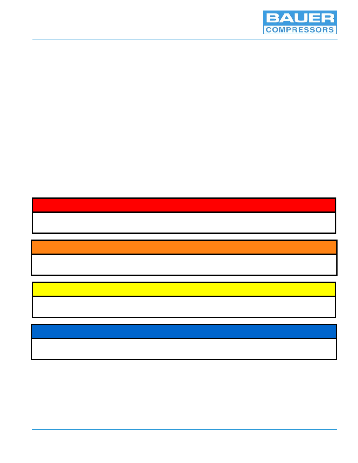
^ DANGER
DANGER indicates an imminently hazardous situation which, if not avoided, will result in death or seri-
ous injury. This is limited to the most extreme situations.
^ WARNING
WARNING indicates a potentially hazardous situation which, if not avoided, could result in death or
injury.
^ CAUTION
CAUTION indicates a potentially hazardous situation which, if not avoided, may result in minor or mod-
erate injury. It may also be used to alert against unsafe practices.
NOTICE
NOTE advise of technical requirements that require particular attention by the operator or the mainte-
nance technician for proper maintenance and utilization of the equipment.
April 4, 2013 Page 1
Page 12
G 120 II V
1.2 How to Use the Replacement Parts List
• A lozenge in the Item Number column indicates the part number for a complete assembly.
• a dagger (†) in the Qty column with or without an ellipse (…) in the Part Number column means the
part is illustrated for assembly purposes only and is not available for sale as an individual component.
This part can be obtained by ordering the complete assembly.
• AR in the Qty column means that the item is cut or manufactured to the size which the customer specifies.
• A dash (—) in the Item Number column indicates that there is more than one part number applicable
to the preceding Item Number.
• The letters in the columns labeled Kit indicate the number of operating hours when the part is to be
replaced; a = replaced every 1,000 hours, b = replaced every 2,000 hours and c= replaced every 4,000
hours.
• NS in the Item Number column indicates the part is not illustrated but is available.
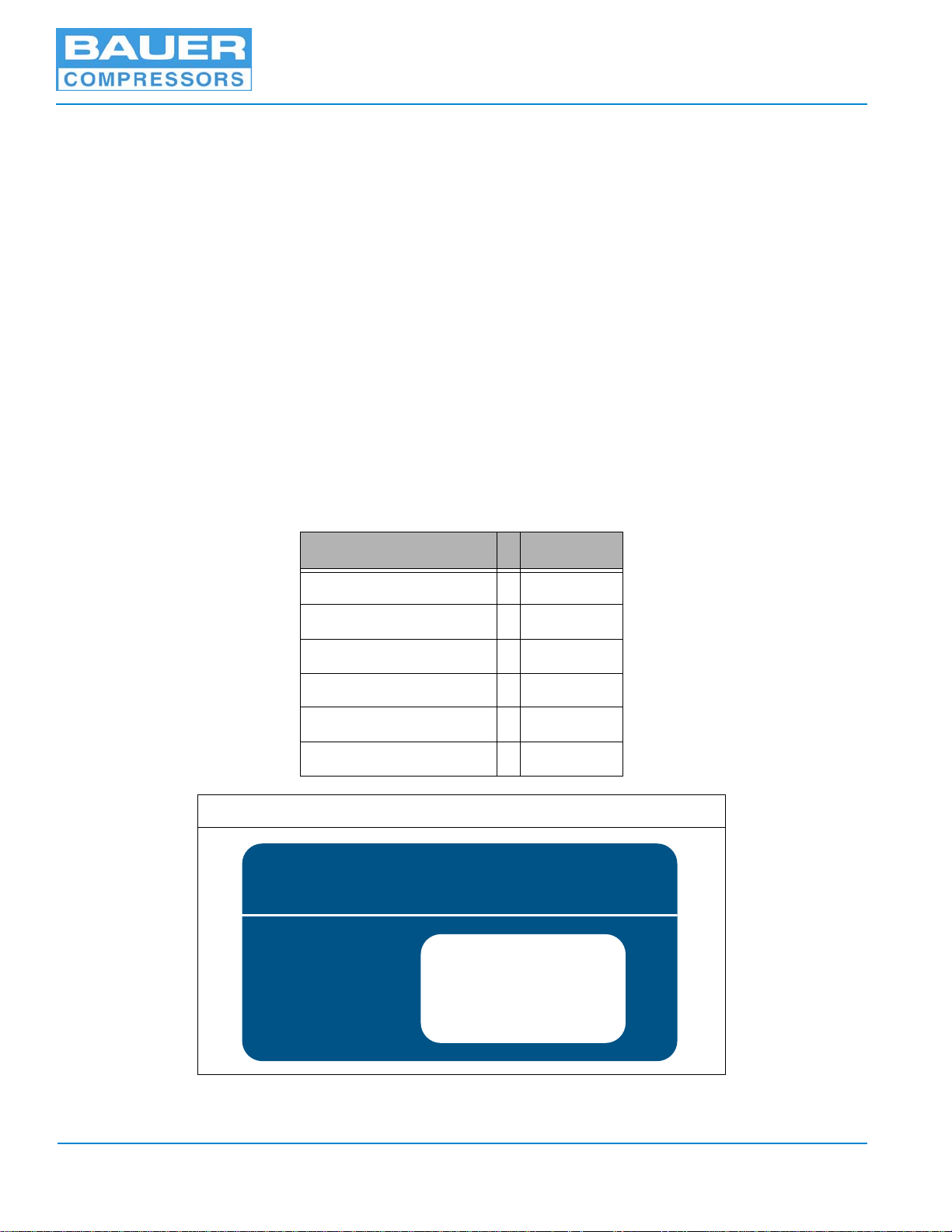
When placing an order for spare parts, please provide the following information to ensure delivery of the
correct parts. The model number, date of manufacture and serial number can be found of the compressor
unit identification plate on the compressor unit frame.
Information Example
Model Number VC 120
Serial Number 143156
Date of Manufacture 02/2013
Part Number VAL-0500
Part Description Valve
Part Quantity Required 1
Figure 1-1 Compressor Identification Label
BAUER COMPRESSORS, INC.
NORFOLK, VA 23502 U.S.A. (757) 855-6006
MODEL NO.
BLOCK NO.
SERIAL NO.
QUANTITY
MFG. DATE
Page 2 1st Edition, Rev. 0 Chg. 2
Page 13

MNL-126509
^ WARNING
The use of repair parts other than those included in the Bauer Replacement Parts Lists may create unsafe
conditions over which Bauer has no control. Such unsafe conditions can lead to accidents that may be life-
threatening, cause substantial bodily injury, and/or result in damage to the equipment. Therefore, Bauer
Compressors, Inc. can bear no responsibility for equipment in which unapproved repair parts are installed.
1.3 How to Use the Appendix
Information contained in the Appendix to this manual includes the following.
• The safety instructions applicable to this product. They must be read, understood and complied with
prior to operating the product.
• The instructions for installing this product. They must be read, understood and complied with prior to
operating the product.
• Reproducible Forms
• Reference Data
• Torque Values
• Torque Sequence
• Conversion Formulas
• Approved Lubricants
• Glossary of Abbreviations & Acronyms
• Additional Documents
April 4, 2013 Page 3
Page 14

1.4 Unit Specifications
All specifications are subject to change without prior notice.
G 120 II V 7.5 Hp
Medium Nitrogen, Helium and Argon
Capacity 6.8 scfm (193 l/min)
Inlet pressure 0 - 3 psig (0 - 0.21 bar)
Operating pressure, max. 5,000 psig (350 bar)
Ambient temperature range 40 - 115 °F (5 - 45 °C)
Compressor Block
IK120 II C Mod. 5
No. of stages 3
No. of cylinders 3
Cylinder bore, 1st stage 3.46 in. (88 mm)
Cylinder bore, 2nd stage 1.42 in. (36 mm)
Cylinder bore, 3rd stage 0.55 in. (14 mm)
Piston Stroke 1.57 in.(40 mm)
Intermediate pressure, 1st stage 85 - 100 psig (6 - 7 bar)
Safety valve setting, 1st stage 130 psig (9 bar)
Intermediate pressure, 2nd stage 580 - 710 psig (40 - 49 bar)
Safety valve setting, 2nd stage 870 psig (60 bar)
Direction of rotation when facing flywheel CCW
Compressor speed 1,200 RPM
Oil capacity 3 qts. (2.8 liter)
Oil Pressure 60 - 85 psig (4 - 6 bar)
Recommended oil BAUER OIL-0024
Maximum Inclination 15° in all directions
G 120 II V
1.4.0.1 Compressor Drive
Model Voltage Freq. Phase Power Type FL Amp Bauer P/N
-E3 208, 230, 460 VAC 60 Hz 7.5 Hp ODP 20, 18, 9 MTR-0033
-E3 380, 400, 415 VAC 50 Hz 7.5 Hp ODP 10.5, 10, 9.5 MTR-0208
1.4.0.2 Purification System Applicability
The G 120 II V is standardly equipped with the Bauer P1 or Oil Removal Filtration System.
1.4.0.3 Pressure Switch Settings
1.4.0.3.1 Inlet Pressure Switch Settings
Low Inlet Pressure 0.0 psig
High Inlet Pressure 1.5 psig
1.4.0.3.2 Final Pressure Switch Setting
Final Pressure 2,400 psig
Restart Pressure 1,900 psig
Final Safety Valve 2,800 psig
Page 4 1st Edition, Rev. 0 Chg. 2
Page 15
MNL-126509
SECURUS
CHAPTER 2: OPERATING INSTRUCTIONS; MAPLE SYSTEM
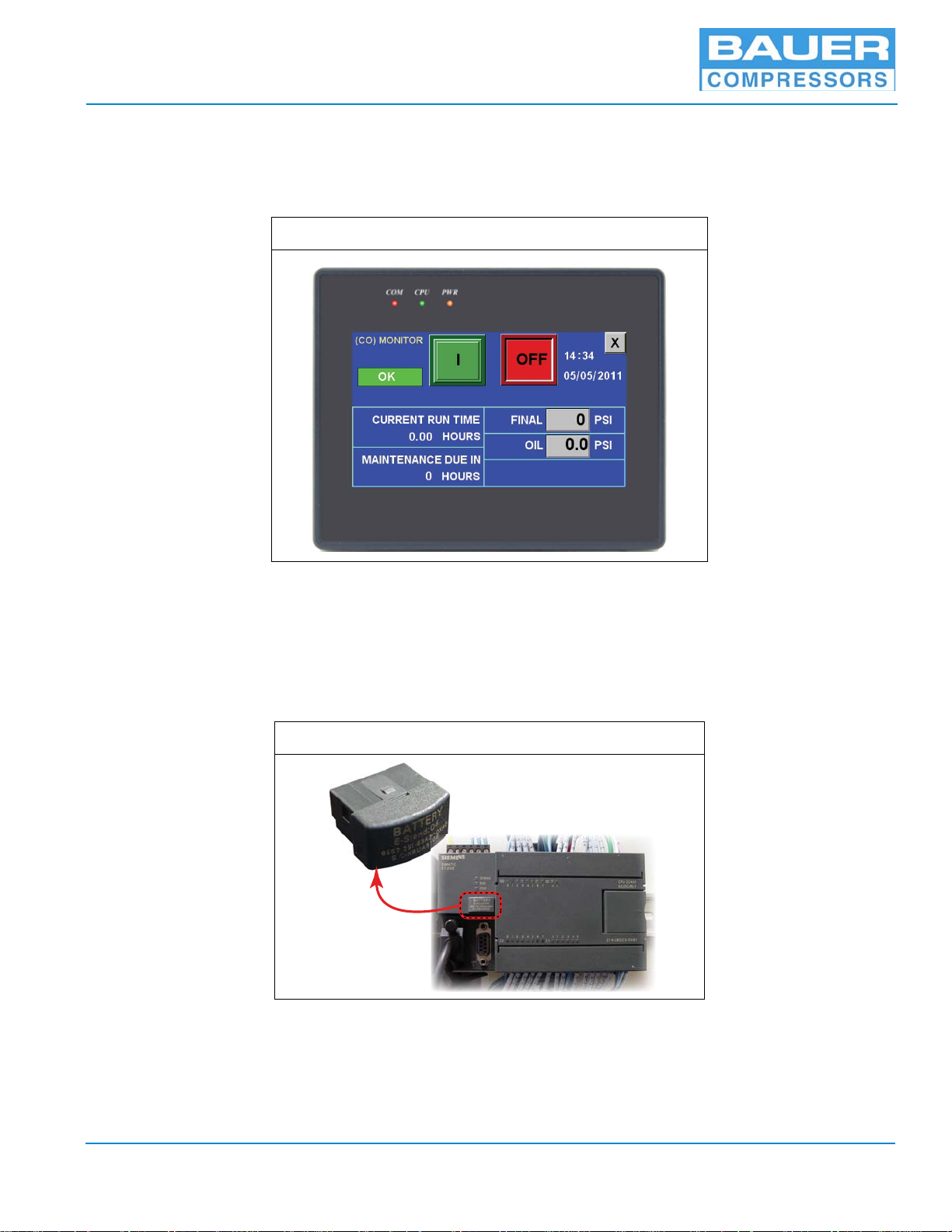
2.1 Description The following instructions apply to units that use the Maple System touchscreen operator interface, MNR-0053 with program 31L.
Figure 2-1 MNR-0053
The Electrical Panel Assembly will provide logical control and safety shutdowns for the compressor
equipment. All necessary time delays, counters, shutdowns, sequencing and safety features are incorporated into a proprietary software program permanently saved into PLC memory using EEPROM technology. The PLC is equipped with a 200 day in battery to maintain the PLC’s internal clock. The software
program is based on the pressure and use of the compressor. The operator uses the Operator Interface to
communicate with the PLC which is located in the electrical enclosure.
2.1.1 Emergency Stop Button
A Normally Closed switch when pulled out, when the E-Stop Button is pressed in, it disconnects the
main power source, turning off the compressor, draining the ACD system and stopping air delivery to
the consuming devices. This button is to be used in case of emergency. Normal operational stops should
be accomplished using the operator interface.
Figure 2-2 PLC & Battery
200 DAY
BATTERY
PLC
April 4, 2013 Page 5
Page 16
G 120 II V
2.1.2 Operator Interface
The Operator Interface is a 4.3 inch, 256 color, 8 bit LCD with touchscreen operation. The Operator
Interface is the input/output device for normal operation of the compressor unit. The compressor system
is ready and able to operate after the Emergency Stop Switch is pulled out and the red “COM” status light
illuminates. The red status light will continuously strobe to show that the unit is ready.
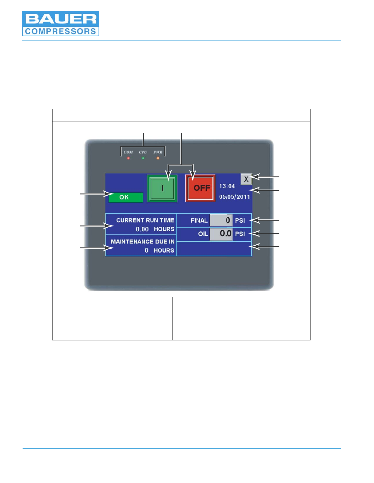
2.1.2.1 Run Screen
The initial screen after startup allows control and monitoring of the compressor unit.
Figure 2-3 Maple System; Run Screen
45
(CO) MONITOR
SECURUS
1
6
7
8
2
9
3
1. Securus / Secant Status
2. Current Run Time
3. Next Maintenance Due Status
4. Status Lights
5. ON & OFF Buttons
1. If the unit is equipped with a CO monitor, the words (CO) monitor are shown here. Also if the unit
is equipped with a Securus or Seccant monitor, the status of the monitor is shown here.
6. Closes Window (goes to main menu)
7. Current Time & Date
8. Final Pressure (from sensor)
9. Current Oil Pressure (from sensor)
10. Inlet Pressure (if equipped with sensor)
10
2. This reading shows the current run time of the compressor in hours. Once the compressor is turned
off this reading returns to zero. For total hours on the unit check the status screen.
3. This reading tells when the next maintenance is due on the compressor.
4. These lights show the status of electrical connections and communication. The red light strobes
continuously to show communication is established with the PLC. The green light indicates that the
PLC has power, and the yellow light indicates power is coming into the unit.
Page 6 1st Edition, Rev. 0 Chg. 2
Page 17
MNL-126509
5. The ON and OFF buttons control the compressor. These buttons should be used for normal starting
and stopping of the compressor. In an emergency the Emergency Stop button should be used.
6. This X button closes the Run screen and goes to the main menu screen. The compressor may still be
operating when returning to the main menu screen.
7. The current time and date are shown here. This data can be corrected only by user levels 2 and 3.
8. The final pressure reading is displayed here. It is received from the final pressure sensor near the
outlet.
9. This oil pressure reading displays a continuous pressure from the compressor. This reading is taken
from the oil pressure sensor on the compressor block.
10. This space a reserved for units with inlet pressure sensors. A continuous inlet pressure reading is
provided. This is mainly for units designed to compress natural or industrial gases.
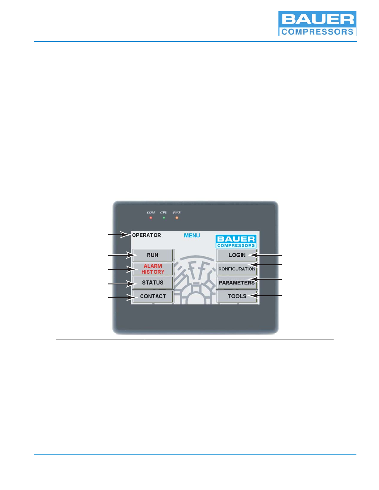
2.1.2.2 Main Menu Screen Figure 2-4 Maple System; Home Screen
1
2
3
4
5
1. User Level Status
2. Run Screen Button
3. Alarm History Button
The home screen is the main screen used to navigate to the other 8 options. All of the option screens can
be viewed but critical changes can only be made by user levels 2 & 3. Critical changes control the functions of the compressor. This feature is added to prevent unintentional changes to the unit’s functions.
2.1.2.2.1 Run
This button returns the user to the RUN screen, See Paragraph 2.1.2.1 for further information.
4. Status Button
5. Contact Information Button
6. Login Button
7. Configuration Button
8. Parameters Button
9. Tools Button
6
7
8
9
April 4, 2013 Page 7
Page 18
G 120 II V
1
2
3
4
5
25.01
15.0
514
2.1.2.2.2 Alarms History
This button displays the history of alarms. The date of the alarm history can be changed with the drop
down arrow or the forward and backward arrows adjacent to the date. To return to the Main Menu screen
touch the X in the upper right corner.
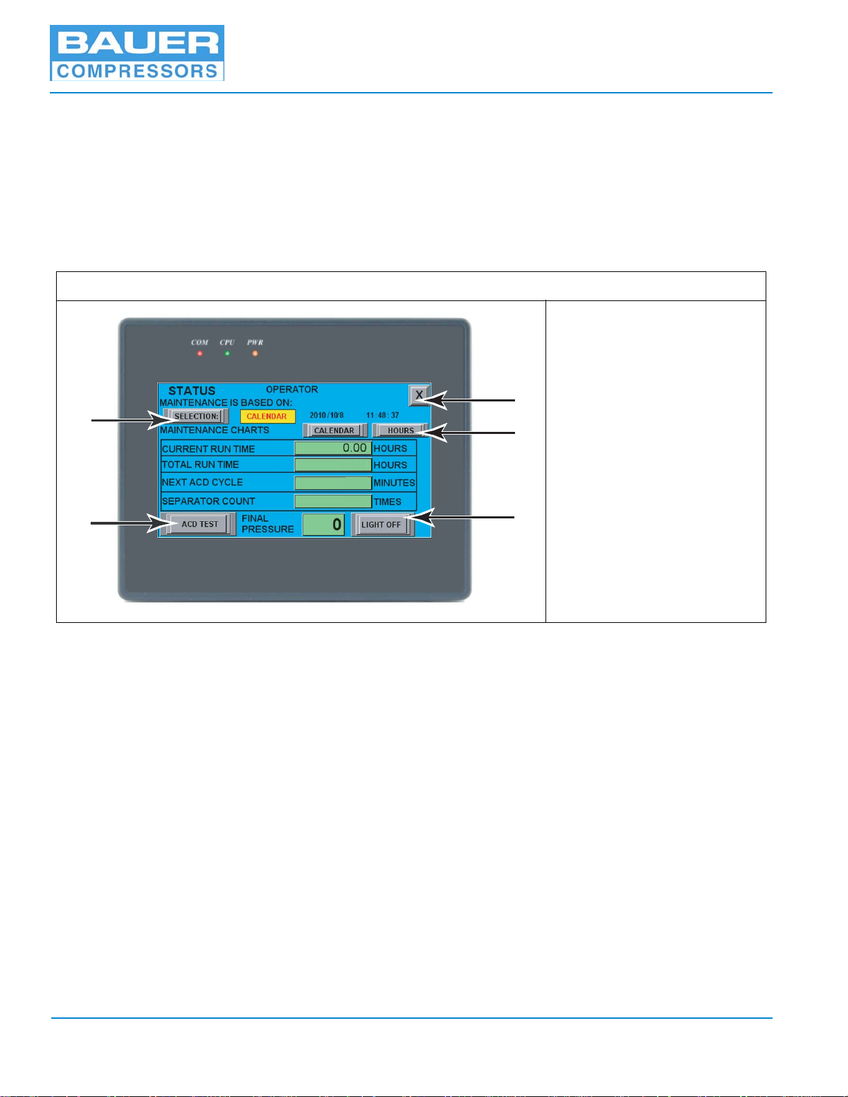
2.1.2.2.3 Status
The status button takes the user to the status screen. The status screen allows the user to view the Current
Run Time, Total Run Time, Minutes till next ACD cycle, current Separator Count, and the Current Final
Pressure.
Figure 2-5 Status Screen
1. Calendar / Hour Selection
2. ACD Test Button
3. Return Button
4. View Maint. Schedule
5. Light ON / OFF Button
The options on the Status screen are shown in Figure 2-5. The Selection button allows the operator to
select maintenance warnings by the calendar schedule or the hourly maintenance schedule. The ACD
Test button is used to perform an ACD test. Pressing this button opens the ACD valve and the operator
should be able to hear the ACD draining. The Return button takes the user back to the Main Menu screen.
The Maintenance schedule buttons allow the user to view the Maintenance schedule by calendar days or
by hours (See Table 2-1& 2-2). The Light ON / OFF button is used on some models equipped with lights.
This button toggles the light on and off.
2.1.2.2.4 Contact
Pressing the contact button displays contact information for maintenance and assistance for your unit. It
can only be edited by users 2 & 3.
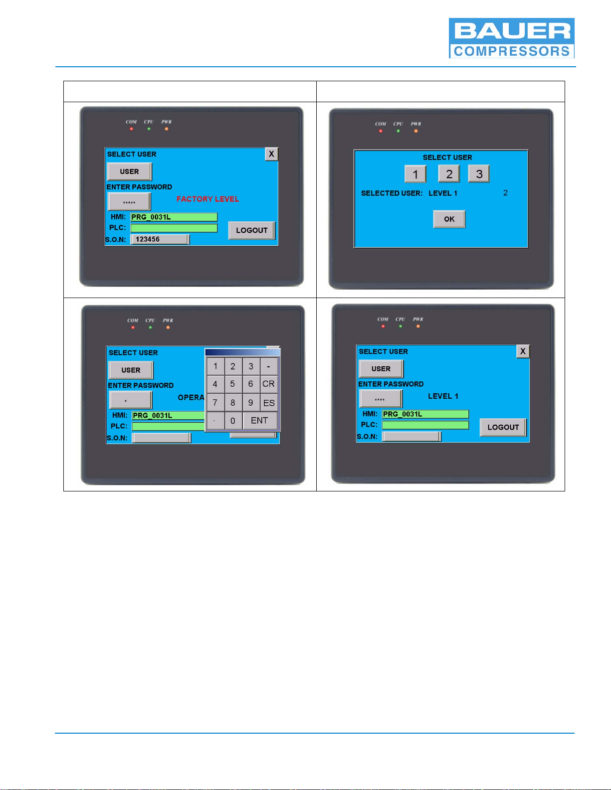
2.1.2.2.5 Login
The login button takes the user to the login screen. The default option is User l, Operator. No password is
needed to operate the compressor at this user level. At this user level the operator can operate the unit and
explore all the other menu screens but cannot change parameters or configuration settings. User 2, Level
1, can operate the compressor and also is allowed to change some parameters and configuration settings.
User 3, Factory Level, has total access to the unit and can change all parameters and configuration settings.
Page 8 1st Edition, Rev. 0 Chg. 2
Page 19
MNL-126509
Figure 2-6 Login Screens
To change the user level press the “USER” button, select the desired user, and press “OK”. Then press the
button below the words “Enter Password” and press the password numbers on the keypad. After entering
the proper password press “ENT” on the keypad to enter the password. If the password is incorrect an
“Invalid Password” screen will pop up. The only option on the screen is to click “OK”. If the password is
accepted the screen will return to the login screen with the new user level shown.
2.1.2.2.6 Configuration
The Configuration button is used to setup the features that make the unit. There are a total of 4 pages in
this option. The first two pages consist of 8 features which a unit may have. The third page is used to set
the final pressure sensor limit. The fourth page is used to set the inlet pressure sensor limit. Similar to the
Parameter’s settings changing the Configuration settings will change how the unit operates so only users
2 & 3 are allowed to change them. Pressing the X button returns the user to the main menu screen.
April 4, 2013 Page 9
Page 20
G 120 II V
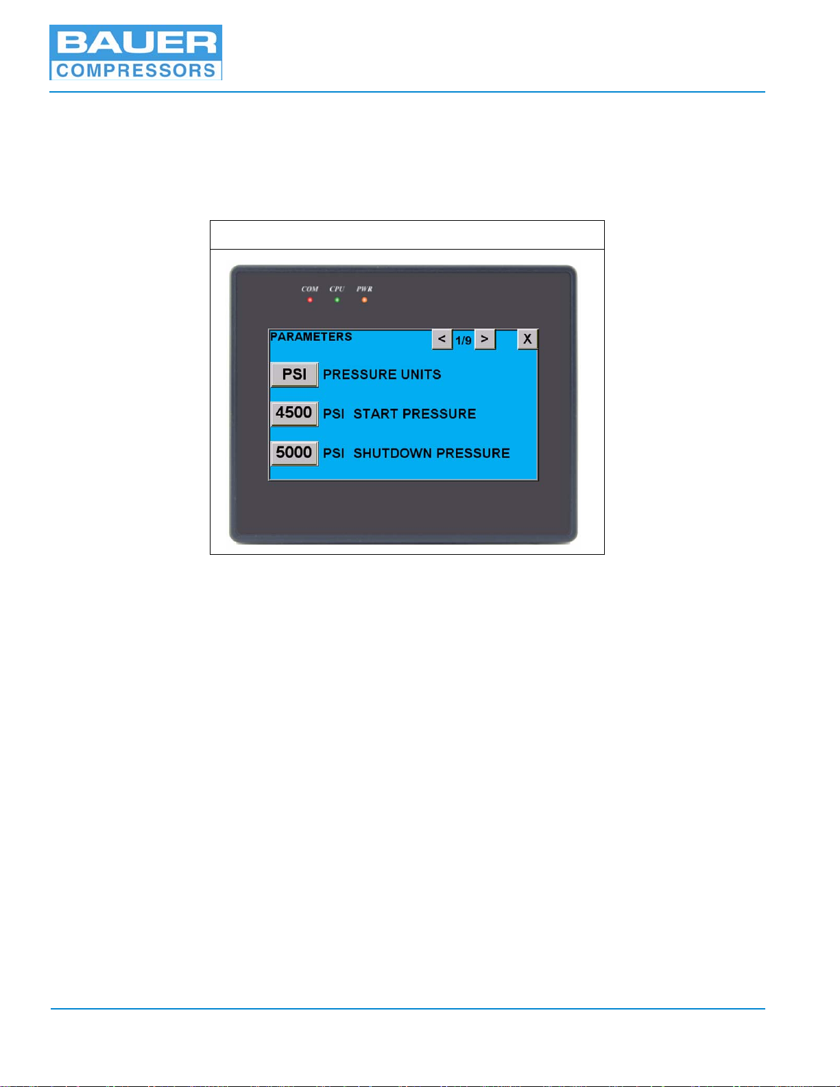
2.1.2.2.7 Parameters
This button takes the user to the parameters screens. There are a total of 9 screens. These parameters are
set at the factory for each specific unit. Changing these parameters will change how the unit operates, so
only users 2 and 3 are allowed to change them. If user 1, Operator, tries to change a parameter a window
will pop up stating “Access Denied”. To change a parameter just touch the number which needs to be
changed and a keypad will pop up. Punch in the new number and press the “ENT” key.
Figure 2-7 Parameters Screen
Pressing the Pressure Units button toggles the run screen pressures between PSI and BAR.
Pressing the X button will return the screen to the main menu.
2.1.2.2.8 Tools
Like the Parameters and Configuration options only users 2 & 3 can make changes or use this option. The
first page of the tools option is used for maintenance purposes. The buttons are used to check the PLC and
can only be used when the unit is OFF. The second page is used to set the internal calendar/clock and to
select the language displayed on the monitor. English, Spanish, and Portuguese are the current choices.
More languages may be added at a later date. The third page offers activation of the Anybus (internet)
Server, to turn off or on the key beeping sound, or to clear the alarm history. The final button “START” is
used to save the current set parameters to the internal EEPROM. If this button is pressed the current setting are saved to the memory and a status bar of the operation will be shown.
2.2 Starting and Stopping Unit
2.2.1 Before Starting.
1. Check the compressor oil level, See Chapter 3.
2. Ensure that all panels and guards are properly installed.
3. If the unit is equipped with doors, ensure all doors are closed.
4. Ensure that the E-Stop Button is pulled out.
Page 10 1st Edition, Rev. 0 Chg. 2
Page 21
MNL-126509
2.2.2 To Start Unit.
Press the green START Button on the Run Screen. (See Figure 2-3)
If the pressure in the system is lower than the set “Start Pressure”, the drive motor will start up powering
the compressor. If the system’s pressure is higher than the set “Start Pressure” or when the air pressure
has increased to the set “Operating Pressure”, the drive motor will automatically shutdown. The Compressor will automatically restart when the system’s pressure drops below the set “Start Pressure”.
^ WARNING
Once started the compressor and drive motor will start and stop automatically.
Stay clear of all moving parts whenever unit has power.
2.2.3 To Stop Unit.
Press the red STOP Button on the Run screen..
NOTICE
In an emergency the compressor is shutdown by pressing
in the Emergency Stop Button.
April 4, 2013 Page 11
Page 22
G 120 II V
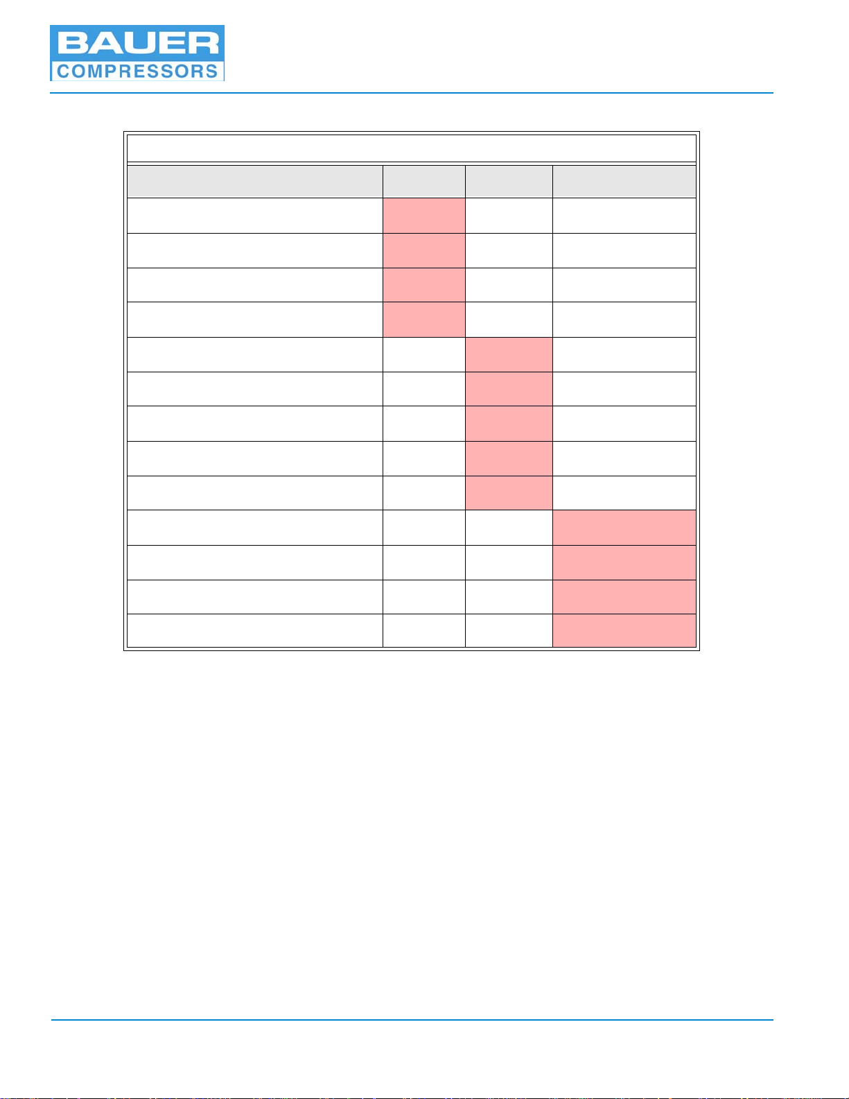
Table 2-1: Calendar Maintenance Interval Tasks
Task Monthly Annually Every Two Years
Calibrate CO Monitor
Check Oil Level
Check Final Pressure Shutdown
Check Automatic Condensate Drain
Check V-belt
Service Intake Filter
Check all connections for leaks
Inspect Compressor Valves
Check all fasteners for tightness
Change Synthetic Oil
Replace Compressor Oil Filter
Replace Compressor Valves
X
X
X
X
X
X
X
X
X
X
X
X
Replace CO Monitor Sensor
X
Page 12 1st Edition, Rev. 0 Chg. 2
Page 23

MNL-126509
Table 2-2: Operating Hours Maintenance Interval Tasks
Task
Check Oil Level
Check Final Pressure Shutdown
Check Automatic Condensate Drain
Check V-belt
Service Intake Filter
Check all connections for leaks
Check fasteners for tightness
Inspect Compressor Valves
Change Synthetic Oil
Replace Oil Filter
Replace Compressor Valves
250
Hours
X
X
X
500
Hours
X
X
X
X
1,000
Hours
X
2,000
Hours
X
X
X
3,000
Hours
Inspect Pistons and Pistons Rings
X
April 4, 2013 Page 13
Page 24
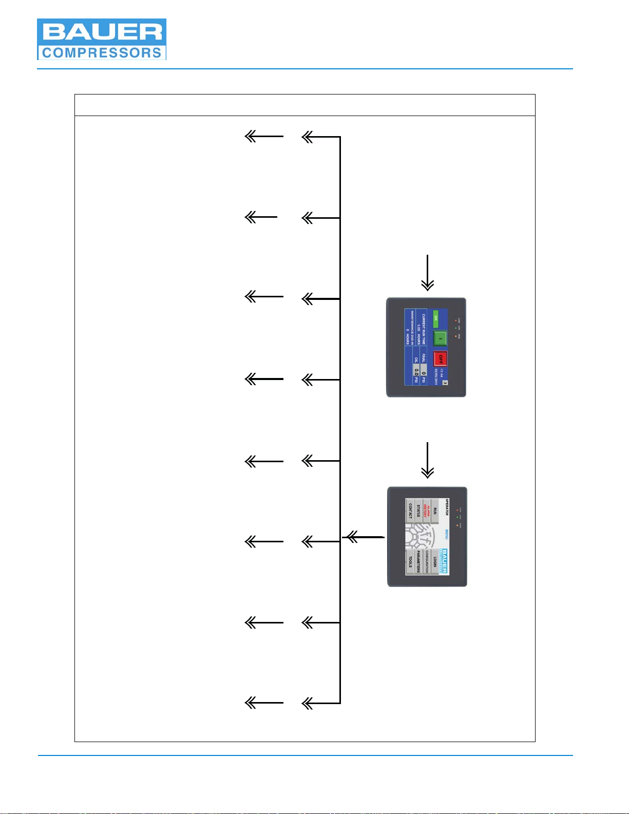
2.3 Screen Flow
START UP
RUN SCREEN
On
Off
MAIN MENU
RUN
Changable
Date
LOGIN
STATUS PARAMETERSCONFIGURATION TOOLSCONTACT
Return to
Run Screen
Above
ALARMS
HISTORY
Users
1, 2, & 3
Current
Status
ACD Test
Light
Unit Settings
9 pages
Unit Setup Maint.
Check
PLC
Set Internal
Clock
Set Language
Contact
Info
for Help
Pressure
Sensor
Limits
Figure 2-8 Operator Interface Screen Flow
G 120 II V
Page 14 1st Edition, Rev. 0 Chg. 2
Page 25
MNL-126509
CHAPTER 3: IK120 II C & G
3.1 Maintenance and Parts
3.1.1 Description
The IK120 II C & G compressors are used to compress gases up to a maximum of 5,000 psi. Both compressors are three cylinder, three stage air cooled, oil lubricated reciprocating compressors. The 3rd stage
cylinder is lubricated by means of the forced feed lubrication system, while the other cylinders are splash
lubricated. The cylinders are arranged in a “W” configuration, the 1st stage is in the center, 2nd stage on
the right and 3rd stage on the left looking from the filter side.
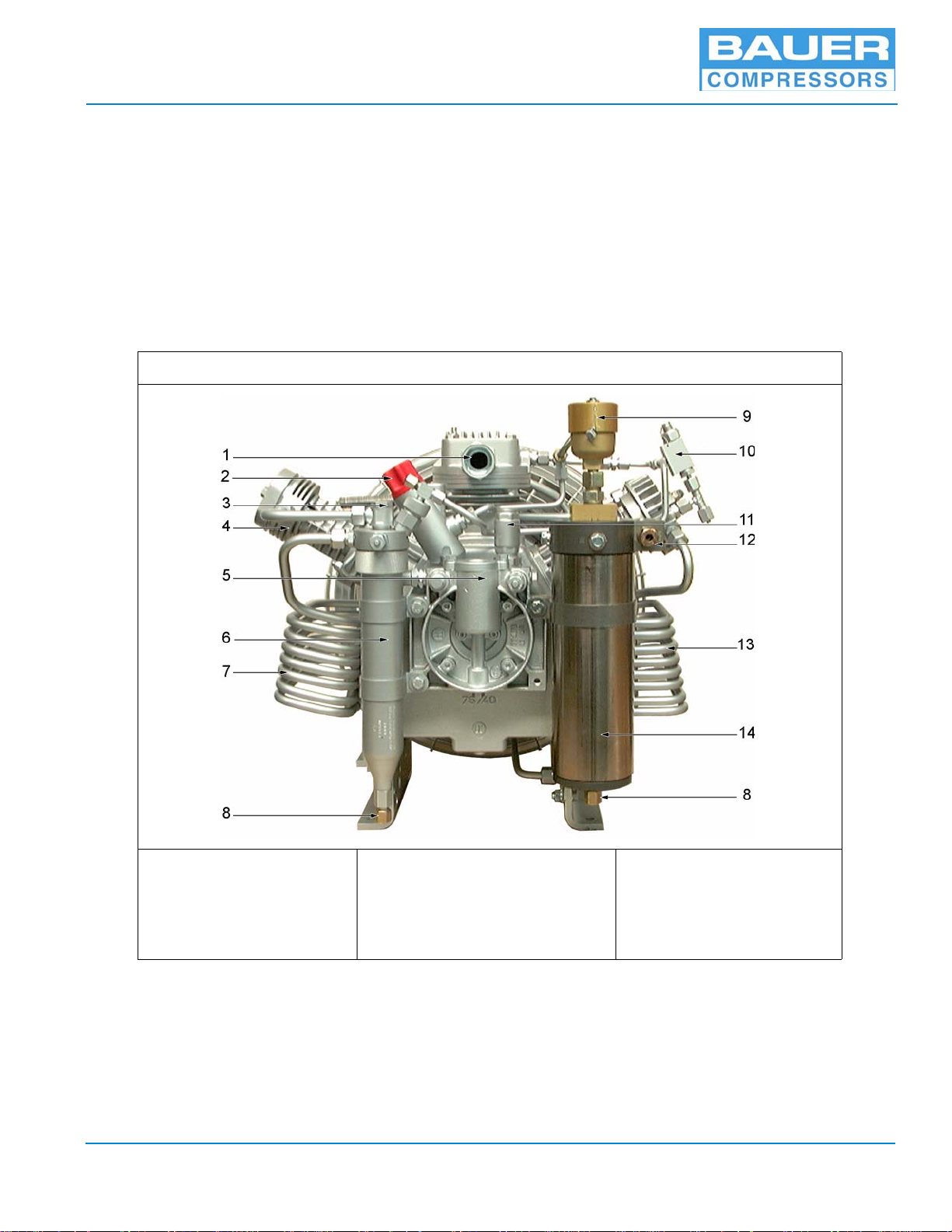
3.1.2 Component Location Figure 3-1 IK120 II C & G Compressor Blocks, Front View
1. Intake Connector
2. Oil Filler
3. 2nd Stage Safety Valve
4. 3rd Stage Cylinder
5. Oil Filter Housing
April 4, 2013 Page 15
6. Inter-stage Separator
7. 2nd Stage Intercooler
8. Condensate Drain Connector
9. Final Safety Valve
10. 1st Stage Safety Valve
11. Crankcase Relief Valve
12. Gas Outlet Connector
13. 1st Stage Intercooler
14. Oil and Water Separator
Page 26
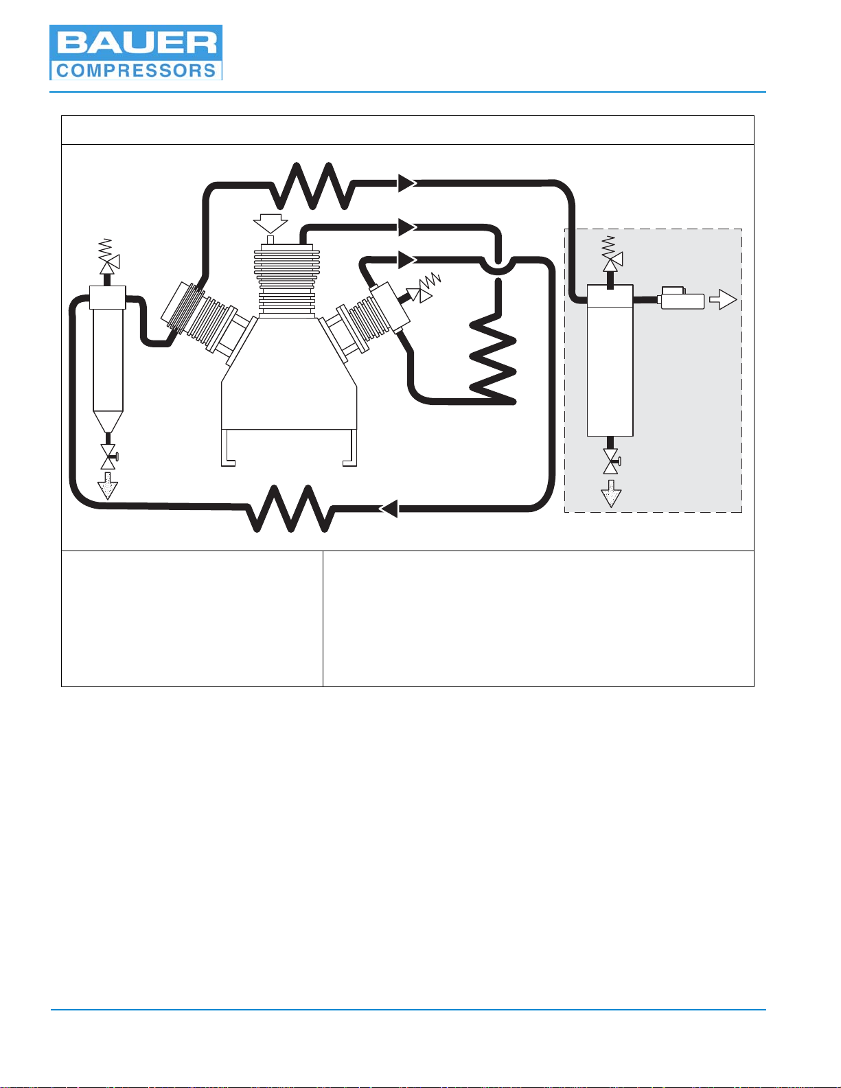
Figure 3-2 Air Flow Diagram
14
11
4
9
2
1
3
8
5
14
12
Purification
System
13
10
6
7
G 120 II V
1. Intake Manifold
2. 1st Stage Cylinder
3. 2nd Stage Cylinder
4. 3rd Stage Cylinder
5. 1st Stage Intercooler
6. 2nd Stage Intercooler
7. 3rd Stage Aftercooler
3.1.3 Air Flow Diagram
Refer to Figure 3-2. The gas is drawn in through intake connector (1), compressed to the final pressure in
cylinders (2, 3, 4,) and cooled by intercoolers (5, 6) and after cooler (7). The safety valves (8,9, 10) protect from overpressure in the individual stages. The compressed gas is purified by Inter-stage separator
(11) and oil and water separator assembly (12). The Inter-stage separator (11) and oil and water separator
(12) are drained by condensate valves (14). An Automatic Condensate Drain system is available as an
option. The pressure maintaining valve (13) ensures that pressure is built up in the HP drying system
from the start of delivery, thus achieving constant optimum drying.
8. 1st Stage Safety Valve
9. 2nd Stage Safety Valve
10. 3rd Stage Safety Valve (Final Pressure)
11. Inter-stage Separator
12. Oil and Water Separator
13. Pressure Maintaining Valve
14. Manual Condensate Drain Valve
Page 16 1st Edition, Rev. 0 Chg. 2
Page 27
MNL-126509
3
2
4
1
5
5
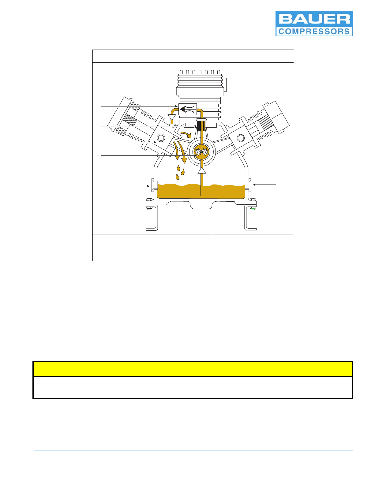
Figure 3-3 Lubrication Oil Circuit
1. Oil Pump
2. Oil Filter
4. Guide Piston
5. Oil Sight Glass
3. Minimum Pressure Valve
3.1.4 Compressor Lubrication
3.1.4.1 Description
Refer to Figure 3-3. The compressor is provided with forced-feed lubrication. The oil pressure is produced by a low speed gear pump (1). The oil pressure is approximately 73 psi (5 bar).
The oil pump (1) is coupled to and driven by the crankshaft. It pumps oil through the oil line filter (2) and
a minimum pressure valve (3) to the 3rd stage cylinder. The oil is then distributed by the guide piston (4)
of the 3rd stage and lubricates all the moving parts of the compressor block.
The minimum pressure valve (3) allows for oil pressure indication at a pressure gauge and/or electronic
oil pressure monitoring.
^ CAUTION
The Oil Pump operates only when the compressor is rotating in the correct direction. If the compressor is
rotating backwards, no oil pressure will build up damaging the compressor.
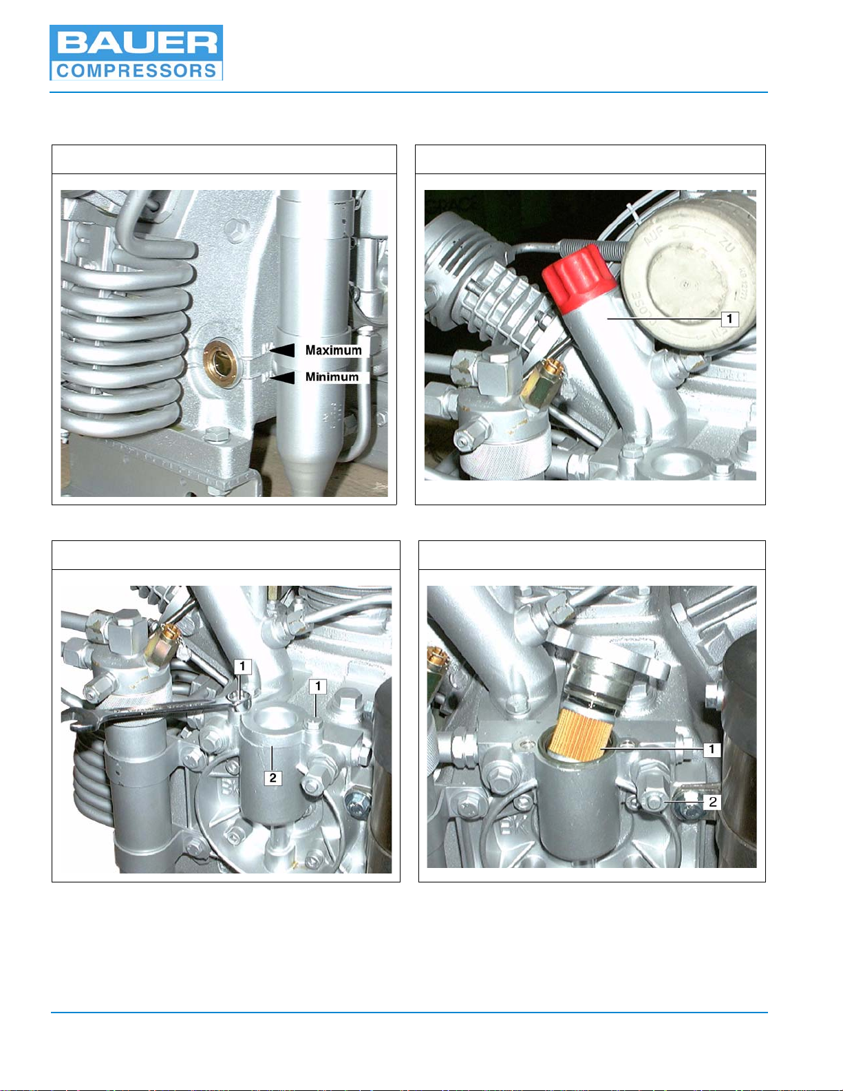
3.1.4.2 Oil Level Check
Check the oil level at the sight gauge on either side of the compressor block (See Figure 3-4) every day
before putting the compressor into operation. Oil level must be between the minimum and maximum
notches. Oil level must never be below the minimum mark as this will cause severe damage due to lack of
April 4, 2013 Page 17
Page 28
G 120 II V
lubrication. Oil level must also not exceed the maximum mark as this will cause excessive lubrication of
the compressor and may result in a carbon buildup on the valves.
Figure 3-4 Oil Sight Glass Figure 3-5 Oil Filler Cap
Figure 3-6 Removing the Oil Filter Cover Figure 3-7 Replacing the Oil Filter
3.1.4.3 Oil Change Interval
Every 2,000 operating hours or biennially; whichever comes first.
Page 18 1st Edition, Rev. 0 Chg. 2
Page 29

MNL-126509
3.1.4.4 Oil Change
1. Run the compressor until it is warm then shut it down.
2. (See Figure 3-5). Remove the cap (1) from the oil filler neck.
3. Drain oil while it is still warm by means of the oil drain plug.
^ CAUTION
Replace the oil filter every oil change. Failure to do so will cause the filter to clog and the bypass valve to
open resulting in unfiltered oil being circulated and possible damage to the compressor.
4. (See Figure 3-6). Remove the two bolts (1) with a 13 mm wrench. Remove the oil filter cover (2)
5. (See Figure 3-7). Remove the oil filter (1) from the rubber gasket at the cover.
6. Mount a new filter element (P/N N25326) and replace and fasten oil filter cover.
7. Slowly pour new oil through the oil filler neck until the level reaches the maximum mark on the
sight gauge.
8. Wait a few minutes and adjust the oil level if necessary before putting the unit into operation.
3.1.5 Venting the Oil Pump
(See Figure 3-7) If no or low oil pressure builds up after starting the unit, especially after maintenance
or repair or if the compressor has been run the wrong direction, venting the oil pump may be necessary.
1. Run the compressor with all condensate drains open to avoid building up pressure.
2. Unscrew Screw Cap (2) and Plug and wait until Oil comes out free of air bubbles.
3. Retighten Plug and Screw Cap.
4. Check Oil Level (See Paragraph 3.1.4.2) and replace oil as necessary.
3.1.5.1 Gas Intake System
In order for these compressors to work satisfactorily, it is absolutely essential to supply the medium at a
constant pressure. Therefore a pressure reducer in the intake line is necessary if the supply pressure is
above atmospheric pressure or fluctuating. An intake expansion tank between the pressure reducer and
the compressor may also be necessary to compensate for the pressure surges caused by the 1st stage piston.
April 4, 2013 Page 19
Page 30
G 120 II V
1
2
3
4
5
6
7
8
3.1.6 Inter-stage Separator
An inter-stage separator is mounted on the compressor block. This separator is designed to remove oil
and water which accumulates due to the cooling of the medium after the compression process. Separation
is achieved by means of centrifugal action provided by a vortex plate (1).
Figure 3-8 Inter-stage Separator
1. Vortex Plate
2. Hollow Screw
3. Center Insert
4. O-ring
^ WARNING
5. Knurled Nut
6. Gasket
7. Fitting
8. Safety Valve
The rapid depressurizing and repressurizing of the inter-stage separator during condensate draining subjects it to metallurgical stresses. To prevent catastrophic failure with the possibility of
damage, injury or death the inter-stage separator must be replaced after 85,000 load cycles. A
load cycle equals one depressurization- repressurization.
Page 20 1st Edition, Rev. 0 Chg. 2
Page 31

MNL-126509
3.1.6.1 Maintenance
The inter-stage Separator requires no maintenance.
3.1.7 Cooling
3.1.7.1 General
The cylinders of the compressor, the inter-stage coolers and the after cooler are air cooled. For this purpose the compressor is equipped with a fanwheel which draws the cooling air through the unit. The fanwheel is driven by the drive motor V-belt and is also used as the compressor flywheel.
3.1.8 Valves and Heads
3.1.8.1 Functional Description
The valve heads of the individual stages form the top part of the cylinders. (See Figure 3-9).
Figure 3-9 Valve Operation
Intake Discharge
The intake and pressure valves are fitted inside the valve heads. Note that the valves are operated by the
flow of the medium. On the intake stroke, the intake valves open and the medium flows into the cylinders. At the start of the pressure stroke the intake valve closes and the medium opens the pressure valve.
The Intake and Pressure Valve of the 1st Stage of the IK120II C & G are a combined plate valve under the
valve head, See Figure 3-10.
April 4, 2013 Page 21
Page 32

G 120 II V
TOP VIEW
Intake Side
Pressure Side
Figure 3-10 IK120II C & G, 1st Stage Valve
3.1.8.2 General Instructions for Changing the Valves
• Always replace valves as a complete set.
• Carefully clean dirty valves. Never use a sharp tool for this purpose. Soak the valves in Varsol and
clean with a soft brush.
• Check the individual components for excessive wear. If the valve seat or valve discs are dented,
replace the valves.
• Check the valve space in the valve heads for dirt, and clean if necessary.
• Use only satisfactory gaskets and O-rings during reassembly.
• Observe the correct sequence when reassembling.
• After finishing all maintenance work on the valves, turn the compressor manually using the flywheel
and check whether all items have been correctly installed.
• 30 minutes after restarting the compressor, stop the unit, let it cool down to ambient temperature, and
retighten valve studs and cap nuts. Otherwise the gasket set may cause a leak.
• Remove and check the valves every 1,000 operating hours.
• Replace the valves every 2,000 operating hours to avoid fatigue failure.
Page 22 1st Edition, Rev. 0 Chg. 2
Page 33

MNL-126509
1
2
3.1.8.3 Changing the IK120 II C & G, 1st Stage Valve
The intake and pressure valve of the IK120 II C & G 1st stage are in a combined plate valve under the
valve head. Refer to Figure 3-11
Figure 3-11 IK120 II C 1st Stage Valve Head and Plate Valve
1. Remove Valve Head (1).
2. Note orientation of Plate Valve (32) before removing it.
3. Reassembly is the reverse of the above steps. Ensure that the Plate Valve mark “TOP” is facing up.
April 4, 2013 Page 23
Page 34

3.1.8.4 Removing the IK120 II C & G, 2nd Stage Valves. Figure 3-12 IK120 II C & G, 2nd Stage Valve Head and Valves
G 120 II V
1. Cap Nut
2. Stud
3. Pressure Plug
4. O-ring
8
7
6
1
2
3
4
5
5. Pressure Valve Insert
6. Intake Valve
7. 2nd Stage Valve Head
8. Allen Screw
See Figure 3-12 and proceed as follows:
1. Remove the intake and pressure lines from the Valve Head (7).
2. Remove the screws (8) holding the Valve Head onto the cylinder.
3. Insert two 8 mm diameter metal pins, any length, in the holes in the Valve Head and secure them in
a vise with the valve head on top.
4. Using the special valve tool, remove the Intake Valve (6) (See Figure 3-13).
^ CAUTION
In order to avoid damaging the special tool or the valve when using the tool, ensure that it is pushed properly and firmly into the valve bore so that it will not tilt when it is turned.
5. Turn the Valve Head over and replace it on the metal pins.
6. Remove the Cap Nut (1).
7. Unscrew the Stud (2) approximately five turns.
Page 24 1st Edition, Rev. 0 Chg. 2
Page 35

MNL-126509
8. Remove the Pressure Plug (3) and take out the valve parts.
9. Clean the Intake Valve and Pressure Valve Assembly, preferably with an ultrasonic cleaner and
check for wear and damage.
10. Valve Seats and Valves must not show any signs of wear or damage. Replace damaged or worn
parts.
Figure 3-13 Using the Special Valve Tool Figure 3-14 Securing the Intake Valve
11. Clean the Valve Head. Check that the intake and pressure valve bores are in perfect condition.
12. Using a precision straightedge, check that the underside of the valve head is flat. If necessary use an
emery cloth and surface plate to smooth out the surface.
3.1.8.5 Reassembling the Valves of the 2nd Stage.
1. Replace the Intake Valve (6) using the special valve tool to tighten it.
^ CAUTION
The intake valve plate and valve spring must not be jammed.
2. Check the intake valve functions correctly by blowing compressed air through the valve in the
direction of flow.
3. Secure the intake valve as follows: (See Figure 3-14) Peen the valve head aluminum over the screw-
in thread of the intake valve in two places opposite one another. Use a small drift pin, approximately
5 mm in diameter.
4. Insert the O-ring (4) and the Pressure Valve parts(5).
5. Check the pressure valve function and stroke by lifting the valve parts.
6. Ensure the Stud (2) is unscrewed, then screw in the Pressure Plug (3)and tighten.
7. Screw the Stud (2) in firmly, fit a new gasket and secure it with the Cap Nut (1).
April 4, 2013 Page 25
Page 36

8. Replace the Valve Head (7) on the cylinder and secure it with the Screws (8).
1
2
3
4
5
6
7
8
9
10
9. Reconnect the intake and pressure lines.
3.1.8.6 Removing the IK120 II C & G, 3rd Stage Valves Figure 3-15 IK120 II C & G, 3rd Stage Valve Head and Valves
G 120 II V
1. Intake Valve
2. Valve Head
3. O-ring
4. Pressure Valve
5. Valve Head Cover
1. Remove the intake and pressure lines from the Valve Head (2).
6. Stud
7. Gasket
8. Cap Nut
9. Screw
10. Washer
2. Remove the Cap Nut (8) and loosen Stud (6) three or four turns.
3. Remove the Screws (9) holding the Valve Head (2) onto the cylinder and take off it off along with
the Valve Head Cover (5).
4. Remove the Pressure Valve (4) by putting two screwdrivers into the removal groove of the pressure
valve body. See Figure 3-16. It may be necessary to loosen the valve body first by turning it with a
13 mm wrench used on the flat surfaces.
5. Insert two 8 mm diameter metal pins, any length, in the holes in the Valve Head and secure them in
a vise with the Valve Head on top of the vise. The Intake Valve (1) should be facing up.
6. Using the special valve tool (See Figure 3-13), remove the Intake Valve (1).
Page 26 1st Edition, Rev. 0 Chg. 2
Page 37

MNL-126509
Figure 3-16 Removing the 3rd Stage Pressure Valve
3.1.8.7 Reassembling the Valves of the 3rd Stage
1. Replace the Intake Valve (1) using the special valve tool to tighten it.
2. Check the intake valve functions correctly by blowing compressed air through the valve in the
direction of flow.
3. Secure the Intake Valve as follows: (See Figure 3-14) Peen the valve head aluminum over the
screw-in thread of the intake valve in two places opposite one another. Use a small drift pin, approximately 5 mm in diameter.
4. Reinstall the Pressure Valve (4) by putting O-ring (3) into Valve Head (2). Check it for abrasions.
5. Insert Pressure Valve (4) through O-ring and into valve bore.
6. Put on Valve Head Cover (5).
7. Reassemble Valve Head Cover and Valve Head to cylinder. Torque screws (9) to the proper value.
8. Screw in Stud (6). Put on Gasket (7). Screw on Cap Nuts (8).
April 4, 2013 Page 27
Page 38

3.1.9 Replacement Parts List
1
2
3
4
4
5
6
7
8
9
10
11
12
13
14
15
16
17
18
19
20
21
23
24
19
25
26
27
28
22
22
16
29
30
Figure 3-17 Crankcase Assembly
G 120 II V
# KIT Qty Part No. Description Notes
1 076743 Crankcase assembly with accessories, driving gear
1 … 1 76740 Crankcase
2 … 1 083399 Crankshaft, complete IK120 II -G/C
3 … 1 N2638 Roller Bearing
4 … 2 N2635 Circlip
5 … 1 66209 Bearing Cap
6 … 1 N15406 Roller Bearing
7 … 1 N15265 O-ring
8 … 1 66684 Cover
9 … 1 N170 Shaft Seal
10 … 1 N3745 O-ring
11 … 1 61054 Plug
12 a.. 1 N15412 O-ring
Page 28 1st Edition, Rev. 0 Chg. 2
Page 39

MNL-126509
Figure 3-17 (cont.) Crankcase Assembly
# KIT Qty Part No. Description Notes
13 … 1 73830 Oil Filling Pipe
14 … 1 N4776 O-ring
15 … 2 N1506 Hex Head Bolt
16 … 8 N58 Washer
17 … 1 N4261 Gasket
18 … 1 N2796 Plug
19 … 2 N25475 Oil Sight Gauge
20 a.. 1 N1316 Gasket
21 … 1 N4570 Plug
22 … 2 78038 Support
23 … 4 WAS-0030 Spring Washer
24 … 4 NUT-0076 Hex Nut
25 … 4 N16 Washer
26 … 4 N350 Hex Head Screw
27 … 3 N19487 Counter-sunk Screws
28 … 1 N2375 Coupling
29 … 1 N25638 Ball Valve oil drain
April 4, 2013 Page 29
Page 40

Figure 3-18 Piston and Cylinder, 1st Stage
1
2
3
4
4
5
7
8
9
6
G 120 II V
# KIT Qty Part No. Description Notes
1 080826 Piston and Cylinder Assembly IK120 II C
1 … 1 80734 Cylinder, IK120 II C 88 mm
2 ..c 1 N4654 O-ring
3 … 1 069975 Piston Assembly, IK120 II C 88 mm (includes #4-6)
4 … 2 N484 Circlip
5 … 1 — Piston Pin
6 … 1 N1787 Piston Ring Set
7 … 4 N215 Stud
8 … 4 WAS-0021 Washer
9 ..c 4 NUT-0119 Self Locking Hex Nut
Page 30 1st Edition, Rev. 0 Chg. 2
Page 41

MNL-126509
1
2
3
4
5
6
7
8
9
9
10
11
Figure 3-19 Piston and Cylinder, 2nd Stage
# KIT Qty Part No. Description Notes
1 85948 Piston and Cylinder Assembly 2nd Stage
1 … 1 62477 Cylinder
2 ..c 1 N7063 O-ring
3 … 1 83404 Guide Cylinder
4 ..c 1 N2640 O-ring
5 ..c 4 NUT-0119 Self Locking Hex Nut
6 … 4 WAS-0021 Washer
7 … 4 N2790 Stud
1 072249 Piston Assembly, Complete Items 8 - 11
8 … 1 62487 Piston
9 … 2 N484 Circlip
10 … 1 N1429 Piston Pin
11 … 1 N2647 Piston Ring Set
April 4, 2013 Page 31
Page 42

Figure 3-20 Piston and Cylinder, 3rd Stage
1
2
3
4
5
6
7
8
9
10
11
12
13
G 120 II V
# KIT Qty Part No. Description Notes
1 83400 Piston and Cylinder Assembly 3rd Stage
1 .b. 1 078043 Piston and Sleeve Assembly See Figure 3-21
2 … 1 82480 Cylinder
3 ..c 1 N7063 O-ring
4 … 1 83404 Guide Cylinder
5 ..c 1 N2640 O-ring
6 ..c 4 NUT-0119 Self Locking Hex Nut
7 … 4 WAS-0021 Washer
8 … 4 N2790 Stud
9 … 1 072165 Guide Piston Assembly Items 10 - 12
10 … † — Guide Piston Available only with 072165
11 … † — Piston Pin Available only with 072165
12 … 2 N484 Circlip
13 a.. 1 N4868 O-ring
Page 32 1st Edition, Rev. 0 Chg. 2
Page 43

MNL-126509
1
2
3
4
Figure 3-21 Piston and Sleeve, 3rd Stage
# KIT Qty Part No. Description Notes
1 078043 Piston and Sleeve Assembly
1 … † — Piston Available only with 078043
2 a.. 1 N23755 O-ring
3 … † — Piston Liner Available only with 078043
4 … 1 N25376 Piston Ring Set Available only with 078043
April 4, 2013 Page 33
Page 44

Figure 3-22 1st Stage Valve Head and Valve, IK120 II C & G
G 120 II V
5
3
6
4
3
2
1
# KIT Qty Part No. Description Notes
1 80727 Valve Head, 1st Stage IK120 II C & G
1 … 1 N26531 Plate Valve IK120 II C & G
2 … 1 80709 Valve Head IK120 II C & G
3…7N102 Washer
4 … 6 N26568 Hex Head Screw
5 … 1 N26646 Hex Head Screw
6 … 1 N4869 O-ring
N.S. 1 73637 Adapter
Page 34 1st Edition, Rev. 0 Chg. 2
Page 45

1
2
3
4
5
9
8
6
10
7
This page is inserted to provide proper page sequencing
Page 46

Figure 3-23 2nd Stage Valves and Valve Head
20
19
18
17
16
15
G 120 II V
8
1
7
6
2
5
4
13
12
11
14
9
10
3
7
# KIT Qty Part No. Description Notes
1 69955 Valve Head, 2nd Stage
1 … 1 14123 Valve Head
2 .b. 1 012841 Intake Valve Assembly Items 3 - 7
3 … 1 † Intake Valve Body Available only with 012841
4 … 1 † Spring Available only with 012841
5 … 1 † Valve Plate Available only with 012841
6 … 1 † Valve Seat Available only with 012841
7 a.. 1 240 Gasket
8 .b. 1 014582 Pressure Valve Assembly Items 9, 15 - 20
9 .b. 1 012835 Pressure Valve Insert Items 10 - 14
10 … 1 † Valve Seat Available only with 012835
11 … 1 † Valve Plate Available only with 012835
12 … 1 1026 Spring
13 … 1 † Valve Insert Available only with 012835
Page 36 1st Edition, Rev. 0 Chg. 2
Page 47

MNL-126509
Figure 3-23 (cont.) 2nd Stage Valves and Valve Head
# KIT Qty Part No. Description Notes
14 a.. 1 N3521 O-ring
15 … 1 14332 Spring Washer
16 … 1 14124 Coupling
17 .b. 1 71064 Stud
18 a.. 1 N3625 Gasket
19 … 1 N84 Cap Nut
20 … 6 19550 Allen Screw
April 4, 2013 Page 37
Page 48

Figure 3-24 3rd Stage Valves and Valve Head
1
2
3
4
5
6
7
8
9
10
G 120 II V
# KIT Qty Part No. Description Notes
1 082096 Valve Head Assembly, 3rd Stage
1 .b. 1 081409 Intake Valve
2 … 1 082087 Valve Head
3 a.. 1 N2789 O-ring
4 .b. 1 014121 Pressure Valve
5 … 1 82086 Valve Head Cover
6 a.. 1 N124608 Stud
7 a.. 1 N3625 Gasket
8 … 1 88609 Cap Nut
9 … 6 N17730 Allen Screw
10 … 6 N58 Washer
Page 38 1st Edition, Rev. 0 Chg. 2
Page 49

MNL-126509
1
2
3
4
5
6
7
8
Figure 3-25 Flywheel
Item Qty Part No. Description Notes
1 82552 Flywheel Assembly
1 1 N1386 Shaft Key
2 1 82553 Hub
3 1 80975 Washer
4 1 N176 Split Washer
5 1 N26666 Bolt
6 1 82496 Flywheel
7 4 N108 Spring Washer
8 4 N19548 Allen Screw
April 4, 2013 Page 39
Page 50

Figure 3-26 Inter-Stage Separator
G 120 II V
4
8
1
2
3
5
6
7
# KIT Qty Part No. Description Notes
1 081799 inter-stage Separator Assembly
1 … 1 81148 Plate
2 … 1 81643 Hollow Screw
3 … 1 76613 Inset Assembly
4 a.. 1 N3556 O-ring
5 … 1 13937 Knurled Ring
6 … 1 N1316 Gasket
7 … 1 N20215 Fitting
8 … 1 072935 Safety Valve 60 bar (870 psi)
Page 40 1st Edition, Rev. 0 Chg. 2
Page 51

1
2
3
4
5
9
8
6
10
7
This page is inserted to provide proper page sequencing
Page 52

Figure 3-27 Lubrication System Assembly
1
2
3
4
5
6
7
8
9
10
11
12
13
14
15
15
15
16
16
15
17
16
18
G 120 II V
# KIT Qty Part No. Description Notes
1 83417 Lubricating System Items 1 - 14
1 … 1 77885 Oil Filter Cover
2 … 1 N4058 O-ring
3 … 1 N25327 O-ring
4 … 1 77774 Rubber Gasket
5 … 1 N25326 Filter Element
6 … 1 77878 Oil Pump Cover
7 … 2 N634 Allen Screw
8 … 2 N2889 Gasket
9 … 1 78421 Gasket
10 … 1 N24585 Gear Pump
11 … 2 N3489 O-ring
12 … 2 N19506 Hex Head Screw
13 … 2 N58 Washer
Page 42 1st Edition, Rev. 0 Chg. 2
Page 53

MNL-126509
Figure 3-27 (cont.) Lubrication System Assembly
# KIT Qty Part No. Description Notes
14 … 1 81050 Regulating Valve
15 … 4 N1316 Gasket
16 … 3 N52 Plug
17 … 1 83420 Connecting Tube Assembly
18 … 1 N20237 Male Connector
April 4, 2013 Page 43
Page 54

Figure 3-28 Cooling System
28
27
4
26
25
3
31
32
20
12
13
24
12
11
21
22
23
12
13
14
15
6
1
12
11
12
11
5
16
17
18
12
19
11
19
12
2
10
8
9
7
30
29
G 120 II V
# KIT Qty Part No. Description Notes
1 83456 IK120 II C & G Cooling System
1 … 1 79486 Intercooler, 1st to 2nd Stage
2 … 1 78195 Intercooler, 2nd to 3rd Stage
3 … 1 070724 Aftercooler
4 … 1 78200 Fanwheel Guard
5 … 1 81802 Safety Valve, 1st Stage 11 bar (160 psi)
6 … 1 072935 Safety Valve, 2nd Stage 60 bar (870 psi)
7 … 4 62773 Mounting Bracket
8 … 4 WAS-0024 Washer
9 … 4 NUT-0118 Self Locking Hex Nut
10 … 4 N3494 Stud
11 … 4 N20059 Fitting
12 … 7 N1316 Gasket
13 … 2 N20195 Male Connector
14 … 1 N4530 Plug
Page 44 1st Edition, Rev. 0 Chg. 2
Page 55

MNL-126509
Figure 3-28 (cont.) Cooling System
# KIT Qty Part No. Description Notes
15 … 1 N3610 Screw Cap, SS
16 … 1 N20327 T- Connector
17 … 1 N15175 Plug
18 … 1 N7433 Screw Cap, SS
19 … 2 N26751 Coupling
20 … 1 N20183 Connector
21 … 2 77894 Clamp
22 … 2 N2460 Washer
23 … 2 N19506 Hex Head Screw
24 … 1 78197 Tubing Assembly
25 … 3 78199 Stud
26 … 3 11887 Mounting Bracket
27 … 3 N58 Washer
28 … 3 N370 Hex Nut, Self-Locking
29 … 1 N20310 Straight Male Connector
30 … 1 81297 Connecting Tube Asy
31 … 1 71148 Connector
32 … 1 56983 Gasket
April 4, 2013 Page 45
Page 56

Figure 3-29 Inlet Assembly
123
INLET
FROM
SUPPLY
TO
COMPRESSOR
INLET
G 120 II V
Item Qty Part No. Description Notes
1 1 SEN-0055 Pressure Sensor 0 -30 psia, 1-11 V
2 1 GAG-00011W Pressure Gauge 30 Hg - 15 psi
3 1 FLR-0009 Filter, Particulate gas tight
— 1 ELM-0040 Filter Element 40 µm
Page 46 1st Edition, Rev. 0 Chg. 2
Page 57

MNL-126509
3.1.10 Troubleshooting and Repair
3.1.10.1 Troubleshooting Table
Trouble Cause Remedy
No oil pressure Low oil level Check oil level
Oil foam in crankcase
Compressor output insufficient
Safety valves between stages
releasing pressure
Compressor running too hot.
1. Last stage piston worn
2. Last stage pressure valve
defective
1. Condensate drain valves or
fittings leaking.
2. Premature opening of final
safety valve.
3. Piston rings worn
4. Excessive piston clearance
5. Pipes leaking
1. inter-stage pressure too
high
2. Valves not closing properly
1. Insufficient supply of cooling air
2. Intake or outlet valve not
closing properly
3. Wrong direction of rotation.
1. Operate compressor with
final stage valve head
removed. If oil flows continuously out of cylinder,
replace piston and sleeve.
2. Replace last stage valves.
1. Tighten and reseal.
2. Clean and adjust final
safety valve.
3. Replace
4. Replace
5. Tighten
1. Service and clean valves.
2. Service and clean valves.
1. Check location for adequate
ventilation
2. Check and clean valves,
replace as necessary
3. Check arrow on compressor
and correct accordingly.
1. Improper maintenance of
Oil residue in delivered air
Compressor rotates in the
wrong direction
April 4, 2013 Page 47
filters, purifier cartridge
saturated.
2. Wrong oil type
Electrical phases not connected
properly
1. Service filters, change purifier cartridge.
2. Change to proper oil and
clean valves.
Reverse two of the three phase
leads at the switch box. Do NOT
change the leads at the motor terminal.
Page 58

G 120 II V
3.1.10.2 Repair Instructions
Repair work can be carried out on the compressor block to a certain extent but a certain level of experience and skill is necessary. It should be noted however that no repair should be carried out on the crankshaft nor on the bearings and safety valves are not repaired but always replaced
Page 48 1st Edition, Rev. 0 Chg. 2
Page 59

MNL-126509
134
5
6
2
3.2 Three Stage Automatic Condensate Drain System
3.2.1 Description
The automatic condensate drain is an optional system and may not be included with your unit.
The automatic condensate drain system operates electropneumatically and is comprised of the following:
An electrically controlled solenoid valve An electrical timer
A pneumatically operated condensate drain valve A condensate manifold
A condensate collector tank
The automatic condensate drain system drains the intermediate separator and the oil and water separator
every 15 minutes during operation. Additionally the automatic condensate drain system unloads the compressor during the starting phase and drains these filters at shutdown of the compressor unit.
Figure 3-30 Automatic Condensate Drain
1. Solenoid Coil
2. Solenoid Valve
3. Blank Off Plate
April 4, 2013 Page 49
4. Condensate Drain Manifold
5. Condensate Drain Valve
6. Manual condensate drain valve
Page 60

Figure 3-31 ACD Operation Diagrams
Normal Operation
Condensate Draining
Condensate
Control Air
2
1
4
Condensate
Control Air
2
1
3
4
3
G 120 II V
1. Solenoid Valve
2. Intermediate Separator
3. Oil and Water Separator
4. Condensate Drain Valve
3.2.1.1 Normal Operation
The normally open solenoid valve (1) controls the condensate draining of the intermediate separator (2).
The normally open condensate drain valve (4) controls the condensate draining of the oil and water separator. The two valves (1 & 4) are connected together in cascade mode. This means that the operational
state (open or closed) of the solenoid valve (1) causes the same state in the condensate drain valve (4) to
occur. The control air for operating the condensate drain valve (4) is taken from the intermediate separator (2).
As the compressor is started, the solenoid valve (1) is electrically energized and closes. This allows the
pressure to buildup in the intermediate separator. This pressure buildup results in control air pressing the
piston into the valve seat, closing the condensate drain valve (4).
3.2.1.2 Condensate Drain
Every 15 minutes the Timer de-energizes the solenoid valve (1) for approximately 10 seconds. The solenoid valve (1) opens and drains the condensation from the intermediate separator (2). This causes a pressure loss in the intermediate separator and the control air for the condensate drain valve (4). As the
pressure of the control air is dropping, the piston of the condensate drain valve (4) becomes unloaded and
the control air is momentarily vented through a relief port. Then the piston of the drain valve is fully
raised by pressure from the final separator, and the condensate is drained.
3.2.1.3 Start Unloading
The unloading of the compressor during the starting phase is possible because of the lack of control air
immediately after starting the unit. As the unit is switched on the solenoid valve (1) is energized and
closes. After the compressor has attained nominal speed, pressure builds in the intermediate separator and
Page 50 1st Edition, Rev. 0 Chg. 2
Page 61

MNL-126509
the control air closes the condensate drain valve (4). Once the valve closes, the compressor delivers to the
consuming device.
3.2.1.4 Standstill Drainage
At compressor shutdown, the solenoid valve (1) is de-energized and opens. This drains the condensate
and relieves the pressure in the intermediate filter (2). This action in turn removes the control air form the
condensate drain valve which opens and drains and relieves the pressure in the oil and water separator.
3.2.2 Component Description
3.2.2.1 Condensate Drain Piping
The outlet opening of the condensate drain manifold is equipped with a tube connector. From here the
condensation is directed into a collecting bottle by means of a tube to the pre-separator elbow and a separator/silencer.
3.2.2.2 Electrical Connection
For electrical connection of the automatic condensate drain, refer to any included wiring diagrams.
^ CAUTION
The condensate drain interval is adjusted at the factory. If the regular operating time of the compressor
unit is less than the drain cycle, adjust the timing relay accordingly to ensure regular draining of the oil
and water separator. If the compressor is shut off before the first drain cycle is completed, the timing relay
would be reset each time causing the drain cycle to be started again. The condensate drain cycle would
never be completed, which could result in flooding of the separator and damage to the connected systems.
3.2.3 ACD Maintenance
The condensate drain valves are provided with manual drain valves to verify correct operation of the
automatic system.
The automatic condensate drain system must be serviced once a week as follows:
1. Open all manual drain valves one after the other.
2. Observe the drainage of condensation.
a. If the system drains more than 2 ounces of liquid per stage, either the system or the corresponding
condensate drain valve is not working properly.
b. Find the fault and remedy accordingly.
3. If little or no condensation emerges, the automatic system is operating properly.
4. The condensate collection tank should be emptied regularly. Due care must be taken to ensure that
any oil which is drained with the condensation is disposed of properly. Check local, state and federal regulations.
April 4, 2013 Page 51
Page 62

3.2.4 ACD Replacement Parts List
134
5
6
2
Figure 3-32 ACD System
G 120 II V
Item Qty Part No. Description Notes
1 DGM-2280 3 Stage Compressor ACD Reference only
1 1 N27288 Electric Coil 115 VAC
or 1 N27757 Electric Coil 12 VDC
2 1 N27099 Solenoid Valve
3 1 PLT-0297 Blank-Off Plate
4 1 MFD-0035 Manifold
5 1 075169 ACD Drain Valve
6 1 011430 Condensate Drain Tap
Page 52 1st Edition, Rev. 0 Chg. 2
Page 63

MNL-126509
1
2
3
4
5
6
7
8
9
Figure 3-33 ACD Valve and Manifold Assembly
Item Qty Part No. Description Notes
1 — ACD Valve and Manifold Assembly
1 1 075169 Condensate Drain Valve Assembly
2 1 PLT-0297 Blank off Plate
3 2 N00638 O-ring
4 1 MFD-0035 Condensate Manifold
5 2 N00829 Socket Head Cap Screw
6 2 N03625 Copper Gasket
7 1 N02507 O-ring
8 1 064004 Valve Connector
9 1 N02320 O-ring
April 4, 2013 Page 53
Page 64

G 120 II V
3.3 Condensate Collector
During compression the water content of the air is also compressed. The resulting water is removed after
each compression stage and is collected through the automatic condensate drain system.
This water, additionally, has a small oil content. The separation of oil and water is not possible through
simple methods; therefore the condensate has to be completely removed. It is most practical to collect this
condensate in special containers and dispose of it entirely.
For these compressor units a metal housing and tank assembly is used. A float level switch is also
included. The condensate is drained from the tank assembly by the manual drain valve into a separate
container for proper disposal.
Figure 3-34 Condensate Collector
1
1. Air Discharge
2. ACD Manifold
2
3
4
3. Float Level Switch
4. Manual Drain Valve
Page 54 1st Edition, Rev. 0 Chg. 2
Page 65

MNL-126509
1
2
3
4
6
7
8
9
11
12
5
10
3.3.1 Condensate Collector Replacement Parts List Figure 3-35 Condensate Collector
Item Qty Part No. Description Notes
1 1 CAP-0056 Condensate Collector Cover
2 1 GKT-0065 Gasket
3 2 ELM-0160 Fine Filter Element
4 2 ELM-0161 Coarse Filter Element
5 1 HUS-0050 Condensate Collector, Inner
6 1 HUS-0060 Condensate Collector, Outer
7 1 SWT-0265 Float Switch
8 1 TNK-0092 Condensate Collection Tank
9 1 RED-0067 Reducer
10 1 VAL-0437 Manual Drain Valve
11 1 PLU-0198 Plug
12 1 MFD-0035 ACD Manifold
April 4, 2013 Page 55
Page 66

G 120 II V
CHAPTER 4: PURIFICATION SYSTEM
4.1 Introduction
The purpose of all Bauer breathing air purification systems is to remove carbon monoxide, oil, water,
taste and odor from the compressed air stream before final delivery.
The purpose of all Bauer industrial air purification systems is to remove oil and water from the compressed air stream before final delivery.
^ WARNING
Industrial Air Purification System cartridges do not remove Carbon Monoxide
and must not be used in breathing air applications.
The quality of gas produced by the compressor is directly related to the quality and temperature of the gas
taken in by the unit. Intake gas should as close as possible to 50 °F (10 °C) and cleanest available and as
dry as possible. Bauer compressors normally add approximately 18 °F (10 °C) to the intake gas temperature. The purification cartridges perform their best at approximately 68 °F (20 °C). Adequate ventilation
enhances the quality and life of the purification cartridges.
4.1.1 General Purification System Procedures
1. Keep an accurate record of operating hours to ensure exact attention to maintenance intervals
2. Change all cartridges before reactivating a compressor unit that has been out of service more than
three months. Leave cartridges in the unit as long as it is out of service.
3. While out of service keep all condensate drain valves closed. Maintain a pressure of 700 - 1,100 psi
(50 to 80 bar) within the system to prevent moisture from entering the compressor and purification
system.
4.1.2 Chamber Safety Bore
The chambers in all Bauer purification systems are designed to prevent pressurization if the cartridge is
missing, not seated properly or damaged (Figure 4-1 & Figure 4-2). Without a cartridge properly in place
the safety bore is not sealed, the air escapes into the atmosphere, no pressure can be built up and thus it is
ensured that unfiltered air is not supplied to the consuming device. If air is escaping from the safety bore
remove and check cartridge. If necessary replace the cartridge or O-rings.
Page 56 1st Edition, Rev. 0 Chg. 2
Page 67

MNL-126509
Figure 4-1 Cartridge Safety Venting Figure 4-2 P0 & P31 Safety Venting
Safety
Vent
Safety
Vent
Cartridge Installed
Correctly
Safety
Vent
No Cartridge or Installed
Incorrectly
Cartridge Installed
correctly
Safety
Vent
No Cartridge Installed
or Installed incorrectly
4.1.3 Manual Condensate Drainage
The condensate must be drained from the oil and water separator before changing any cartridge, before
beginning each filling procedure and in the absence of an Automatic Condensate Drain (ACD) system,
every fifteen minutes during the filling procedure. This is done by slowly opening the condensate drain
valves. They are opened approximately 1/3 of a turn to the left and held open until the condensate is completely drained. The condensate drain valves close by spring pressure but if necessary may be tightened
by hand to ensure they are completely air tight.
4.1.4 Model, Serial Number and Part Number Identification
4.1.4.1 Compressor Dataplate
The model number, date of manufacture and serial number can be found on the compressor unit identification plate in the main electrical enclosure and frame.
Figure 4-3 Purification System Dataplates (typical)
Purification System Cartridge Installation
PURIFICATION
SYSTEM
MODEL NO.
MAX. PRESSURE
AIR PROCESSED
O-RING
BACK-UP RING
psig
cu. ft .
LBL-0191
CARTRIDGE TO BE
INSTALLED
CARTRIDGE FOR
CARTRIDGE NO.
1328 Azalea Garden Road - Norfolk Virginia 23502-1944
Phone: (757) 855-6006 Fax: (757) 855-8224
LBL-0044
April 4, 2013 Page 57
Page 68

G 120 II V
4.1.4.2 Purification System Dataplate
Refer to the compressor unit purification system data plate (Figure 4-3) on the compressor front to determine your purification system model and specifications.
4.1.4.3 Cartridge Installation Dataplate
The function performed by each chamber in the purification system is determined by the type of cartridge
installed in that chamber. Refer to the cartridge installation data plate on the chamber to determine the
purpose and part number of the cartridge installed in that chamber. (Figure 4-3).
4.1.5 Breathing Air Purification System Configurations Purification System Number and Type of Cartridges Processing Capacity
Dryer Purification Securus®
cubic ft (ft)
P0 Combined 3,200
P1 … 1 … 15,000
P2 … 1 … 40,000
P2 with Securus
®
… … 1 67,000
P4 1 1 … 60,000
P5 1 1 … 90,000
P5 with Securus
®
1 … 1 150,000
P10 2 1 140,000
P10 with Securus
a
P12
a
P14
®
2 … 1 230,000
1 1 420,000
2 1 650,000
P31 Combined 11,760
3
P41 … 1 28,700
P41 with Securus
®
… … 1 47,000
P42 1 1 … 64,000
P42 with Securus
®
1 … 1 107,000
P43 2 1 … 100,000
P43 with Securus
®
2 … 1 164,000
P81 1 1 124,000
P81 with Securus
a. P12 and P14 have the Securus® Electronic Moisture Monitor System as standard equipment.
®
1 ... 1 198,000
Page 58 1st Edition, Rev. 0 Chg. 2
Page 69

MNL-126509
4.1.6 Industrial Purification System Configurations Purification System Number and Type of Cartridges Processing Capacity
Dryer Purification Securus®
cubic ft (ft)
P0 Combined 3,200
P1 … 1 … 15,000
P2 … 1 … 40,000
IP2 with Securus
®
… … 1 67,000
P4 1 1 … 60,000
P5 1 1 … 90,000
IP5 with Securus
®
1 … 1 150,000
P10 2 1 140,000
IP10 with Securus
®
2 … 1 230,000
P31 Combined 11,760
IP41 with Securus
IP42 with Securus
IP43 with Securus
®
®
®
… … 1 47,000
1 … 1 107,000
2 … 1 164,000
3
4.1.7 Cartridge Operating Life
Every Bauer Purification System is designed to process a certain volume of air before the cartridges
require replacement. By using special test equipment that measures the quality of air at the outlet any
quality reduction may be detected. However as most compressor owners do not have this test equipment
the recommended method of determining cartridge operating life is to maintain a written record of the
volume of air processed by the purification system.
Each Bauer compressor block is rated to produce a standard volume of air per minute and by using this
number and the air processing capability of the purification system it is possible to calculate the maximum operating hours before the cartridges need to be replaced. See Paragraph 4.1.7.1 for the method of
determining this figure.
The ambient air temperature and its ability to cool the compressor will effect the operating life of the cartridge. See Paragraph 4.1.7.2 for the method of calculating this adjustment factor.
The optimum place to measure the temperature is at the inlet to the final separator as this best reflects the
temperature of the air as it enters the chambers. Experience has shown that this temperature is approximately 18 °F above the ambient temperature. Therefore for the purpose of calculating cartridge operating
life use the Ambient Air Temperature plus 18 °F.
A form titled Air Purification Cartridge Operating Hours is found in Paragraph 4.1.7.3 and in the
Appendices. It is used for recording the ambient temperature, operating time and adjustment factor. It
April 4, 2013 Page 59
Page 70

G 120 II V
is suggested that it be copied, placed in a protective folder and kept with the unit to record the adjusted
operating hours. An example of how this form is used is shown in Figure 4-5.
4.1.7.1 Calculating the Maximum Cartridge Operating Hours
1. From the purification system data plate (See Figure 4-3) on the purification chamber determine the
Air Processed (cu.ft.)
2. From the paragraph titled Compressor Specifications in the instruction manual for your compressor
unit determine the Charging Rate in SCFM of your compressor.
3. Divide the Air Processed by the Charging Rate to obtain the Maximum Operating Time in minutes
4. Divide the Maximum Operating Time in minutes by 60 to obtain the Maximum Operating Hours.
5. Record the answer on the Air Purification Cartridge Operating Hours form.
4.1.7.2 Calculating the Adjusted Cartridge Operating Hours
1. Using the Air Purification Cartridge Operating Hours form (FORM-0018) record the Date, Operat-
ing Hours and Ambient Air Temperature plus 18 °F.
2. Using either the graph or the chart in Figure 4-4 determine the Correction Factor.
3. Divide the Operating Hours by the Correction Factor and record it under the column labeled Today.
4. Add the hours recorded in Today to the previous Total and record it as the current Total.
5. When the Total approaches the Maximum Operating Hours replace the Cartridges.
Page 60 1st Edition, Rev. 0 Chg. 2
Page 71

MNL-126509
°F
[°C x 9/5 +32]
°C
[
(°F - 32) x 5/9]
Correction Factor
50 122 0.21
40
104 0.34
30 86
0.58
20 68 1.00
10
50 1.81
0
32
3.44
0.0
0.5
1.0
1.5
2.0
2.5
3.0
3.5
0 °C
10 °C 20 °C 30 °C 40 °C 50 °C
Conversion Factor
32 °F 50 °F 68 °F 86 °F 104 °F 122 °F
Date
Operating
Hours
Ambient Temp.
during Compression +18 °F
Correction
Factor
Adjusted Cartridge Hours
Today Total
10/19/04 8 92°F
(33 °C)
0.5 16.00 16.00
11/01/04 4 45°F
(7.2 °C)
2.25 1.78 17.78
Op hrs
Corr. factor
Total hrs
+Today hrs
Figure 4-4 Correction Factor for Cartridge Operating Hours
Figure 4-5 Example Record of Adjusted Operating Hours
April 4, 2013 Page 61
Page 72

4.1.7.3 Air Purification Cartridge Operating Hours Form
G 120 II V
Date
Operating
hours
Ambient temp. + 18°F
during compression
Correction
factor
Adjusted cartridge hours
Today Total
Page 62 1st Edition, Rev. 0 Chg. 2
Page 73

MNL-126509
OUT
IN
1
2
3
4 5
6
3
7
4.2 P1 Purification System
4.2.1 Major Components
The P1 Purification System major components are a Oil and Water Separator and a Purification Chamber.
Figure 4-6 shows the functional interconnection of all the components.
Figure 4-6 P1 Purification System
1. Oil and Water Separator
2. Condensate Drain Valve
3. Check Valves
5. Bleed Valve
6. Pressure Maintaining Valve
7. Safety Valve
4. Chamber
April 4, 2013 Page 63
Page 74

G 120 II V
4.2.2 Component Description
4.2.2.1 Oil & Water (condensate) Separator
^ WARNING
The rapid depressurizing and repressurizing of the oil and water separator during condensate draining sub-
jects it to metallurgical stresses. To prevent catastrophic failure with the possibility of damage, injury or
death the oil and water separator (P/N 079416) must be replaced after a predetermined number of cycles.
One load cycle equals one pressurization plus one depressurization.
Units operating between 3,000 and 5,000 psi = 130,000 load cycles (32,500 hours of operation)
Units operating between 5,000 and 6,000 psi = 55,000 load cycles (13,750 hours of operation
The Bauer recommended frequency of condensate draining is every fifteen minutes and is a balance
between maximizing the life of the separator chamber and maintaining the quality of the delivered air.
The air leaving the final stage is cooled in the aftercooler to approximately 18 - 27° F (10 -15° C) above
ambient temperature and then enters the oil and water separator. The oil and water separator works by
means of a sintered metal filter which separates liquid oil and water particles from the compressed air.
Figure 4-7 Oil and Water Separator
Page 64 1st Edition, Rev. 0 Chg. 2
Page 75

MNL-126509
Protective Cap
Purification
Cartridge
Figure 4-8 Oil and Water Separator Labels
4.2.2.2 Chamber
Each chamber is made up of an anodized aluminum housing and a filtering cartridge. There are two general types of filtering cartridges, drying or purifying. The cartridge type is determined by the ingredients
packed in the cartridge. The chamber is named after the type of cartridge it contains, i.e. dryer chamber or
purification chamber.
4.2.2.3 Cartridge
The cartridge casing, top and bottom are aluminum and are packed with
one or more of the following.
1. A catalyst to convert carbon monoxide to carbon dioxide.
2. Activated carbon which absorbs oil vapors effecting taste and odor.
3. Molecular sieve to absorb oil and water.
4.2.2.4 Cartridge Handling
4. Never open the protective packaging a cartridge comes in prior to its
actual use. The highly sensitive filter materials will absorb moisture
from the atmosphere becoming saturated and useless.
5. Used cartridges must be disposed of in accordance with local regulations.
4.2.2.5 Condensate Drain Valve
A manually operated valve used for maintenance and before start-up to drain the condensed liquids from
the coalescing oil and water separator.
4.2.2.6 Check Valves
Valves allowing compressed air to flow in only one direction. One is used to maintain pressure in the
chamber when the compressor is not operating. The other check valve prevents back-flow from filled
storage cylinders or tanks.
April 4, 2013 Page 65
Page 76

G 120 II V
4.2.2.7 Bleed Valve
A manually operated valve used to release the pressure in the chamber before maintenance.
4.2.2.8 Pressure Maintaining Valve
The pressure maintaining valve ensures that pressure is built up in the system from the start of delivery,
thus achieving constant optimum purification. It also assures proper working conditions for the final
stage of compression.
4.2.2.9 Safety Valve
The safety valve is located on the coalescing oil and water separator and acts as the safety valve for the
final stage of the compressor.
4.3 Maintenance
4.3.1 Oil and Water Separator
To remove the sintered metal filter proceed as follows: (See Figure 4-9). Disconnect the power and shut
off the inlet supply line if applicable.
1. Depressurize the system by means of the bleed valve.
2. Remove the tubes connected to the side of the filter head (1).
3. Unscrew and remove the filter head.
4. Unscrew the sintered metal filter (2) from the filter head.
5. Remove the center screw (3) to remove the sintered metal filter.
6. Clean the sintered metal filter using hot soapy water. Blow dry with compressed air.
7. After cleaning the element, record the number of operating hours to ensure exact attention to the
maintenance intervals.
8. Lubricate the threads and O-rings as well as the threaded part of the sintered metal filter with petroleum jelly. Apply sparingly.
9. Dry the inside of the filter housing with a clean cloth and check for corrosion before reinstalling the
sintered metal filter.
10. In the event you discover corrosion, replace the corroded parts with new Bauer parts.
11. Reinstall the sintered metal filter assembly and filter head.
12. Replace all removed tubes, close all valves and check for leaks.
Page 66 1st Edition, Rev. 0 Chg. 2
Page 77

MNL-126509
1
2
3
4
Figure 4-9 Oil and Water Separator Figure 4-10 Sintered Metal Filter Assembly
1. Filter Head
2. Sintered Metal Filter
3. Center Screw
4. O -rings
4.3.2 Cartridge Replacement
To change the purification cartridge, proceed as follows. (See Figure 4-11)
Figure 4-11 Cartridge Replacement
Pull
Up
1. Disconnect the power and shut off the inlet supply line, if applicable.
2. Depressurize the system by means of the bleed valve.
3. Unscrew the chamber head using the special wrench supplied.
April 4, 2013 Page 67
Page 78

G 120 II V
4. Pull out the cartridge using the lifting ring on top of the cartridge.
5. Dry the inside of the chamber with a clean cloth and check for corrosion.
6. Replace all corroded parts with new Bauer parts.
7. Remove the shipping covering and the protective cap from the bottom of the cartridge.
8. Lubricate the O-rings with white petroleum jelly. Apply sparingly.
9. Install the new cartridge. Be sure the cartridge snaps into place.
10. Reinstall the chamber head.
11. Close the bleed valve, restore the power and reconnect the inlet supply line, if applicable.
NOTICE
If air is detected bleeding out from the bottom of the chamber, the cartridge has not been installed properly
or is missing. Follow the instructions in Paragraph 4.3.2.1
4.3.2.1 Leaking at the Safety Bore
1. Remove the cartridge following steps 1. to 4. in Paragraph 4.3.2.
2. Install cartridge if missing.
3. Remove cartridge and inspect O-rings.
4. Replace O-rings if necessary.
5. Ensure protective caps and devices have all been removed.
6. Replace cartridge following steps 8. to 11. in Paragraph 4.3.2
Page 68 1st Edition, Rev. 0 Chg. 2
Page 79

MNL-126509
OUT
IN
1
2
3
4 5
6
3
7
4.4 Replacement Parts List Figure 4-12 P1 Purification System Parts List
Item Qty Part No. Description Notes
1 1 079416 Oil and Water Separator See Figure 4-13
2 1 011430 Condensate Drain Valve
3 2 VAL-0007 Check Valves
4 1 080143 10” Purification Chamber See Figure 4-14
5 1 VAL-0377 Bleed Valve
6 1 VAL-0053 Pressure Maintaining Valve
7 1 VAL-0169 Safety Valve
April 4, 2013 Page 69
Page 80

Figure 4-13 Oil and Water Separator Parts List
1
2
3
4
5
2
a
b
c
b
c
d
e
f
g
G 120 II V
Item Qty Part No. Description Notes
1 079416 Oil and Water Separator Assembly
1 † … Separator Head Available only with 079416
2 2 N04586 O-Ring
3 1 061860 Sintered Metal Filter
3a 1 N15133 O-Ring
3b 2 N04496 O-Ring, small
3c 2 N04385 O-Ring, large
3d 1 061858 Sleeve Element, large
3e 1 061859 Sleeve Element, small
3f 1 N07091 O-Ring
3g 1 061857 Screw
4 † … Separator Housing Available only with 079416
5 † … Bottom Plug Available only with 079416
Page 70 1st Edition, Rev. 0 Chg. 2
Page 81

MNL-126509
Figure 4-14 10” Chamber Parts List
1
2
3
4
5
6
8
5
4
7
9
10
Item Qty Part No. Description Notes
1 080143 Chamber Assembly 10”
1 2 012293 Tool Post Screw
2 1 061237 Cover Plate
3 † … Filter Head Available only with 080143
4 2 N04736 Back-up Ring
5 2 N04735 O-ring
6 † … Filter Housing Available only with 080143
7 † … Filter Bottom Available only with 080143
8 1 058817 Purification Cartridge AC, 10”
9 1 N04731 O-ring
10 1 N04566 O-ring
April 4, 2013 Page 71
Page 82

G 120 II V
CHAPTER 5: COMPRESSOR DRIVE; G 120 II V
5.1 Vertical Compressor Drive
The compressor is driven by the drive motor through a V-belt. The direction of rotation, as seen facing
the flywheel, is counterclockwise. Observe the arrow on the compressor block. Check the V-belt regularly for damage and wear. See Paragraph 5.2.2. Replace if necessary.
Figure 5-1 Vertical Drive with Idler (typical)
N
O
I
T
A
T
O
R
1
2
3
4
5
6
1. Compressor flywheel
2. V-belt
3. Spring Tension Idler
4. V-belt sheave
5. Bushing
6. Electric motor
5.2 Maintenance of the V-belt and Sheaves
5.2.1 Check The Sheaves.
Before a new set of drive belts are installed, the condition of the sheaves should be checked. Dirty or
rusty sheaves impair the drive’s efficiency and abrade the cover of the belts, which results in premature
failure. Worn sheaves shorten belt life as much as 50%. If the grooves are worn to the point where the belt
bottoms, slippage may result and the belts may burn. If the side walls are “dished out,” the bottom shoulder ruins the belt prematurely by wearing off the bottom corners.
5.2.2 Check the V-belt
Check the V-belt regularly for damage and wear. Replace if necessary. V-belt tension is adjusted automatically by the spring tension idler.
Page 72 1st Edition, Rev. 0 Chg. 2
Page 83

MNL-126509
1
2
3
4
5
6
R
O
T
A
T
I
O
N
5.3 Replacement Part List
Figure 5-2 G 120 II V Drive with Idler
Item Qty Part No. Description Notes
G 120 II V, 60 Hz
1 1 IK120 II C Compressor Block
2 1 BET-0214 V-belt
3 1 IDL-0010 Idler
with 1 PLY-0006 Idler Pulley
4 1 SHE-0139 Sheave
5 1 BUS-0002 Sheave Bushing
6 1 MTR-0033 Electric Motor 7.5 Hp, 3 Phase, ODP
April 4, 2013 Page 73
Page 84

Figure 5-2 (cont.) G 120 II V Drive with Idler
Item Qty Part No. Description Notes
G 120 II V, 50 Hz
1 1 IK120 II C Compressor Block
2 1 BET-0259 V-belt
3 1 IDL-0010 Idler
with 1 PLY-0006 Idler Pulley
4 1 SHE-0321 Sheave
5 1 BUS-0158 Sheave Bushing
6 1 MTR-0208 Electric Motor 7.5 Hp, 3 Phase, ODP
G 120 II V
Page 74 1st Edition, Rev. 0 Chg. 2
Page 85

MNL-126509
CHAPTER 6: ELECTRICAL PANEL, ASY-1058 XL
6.1 Overview
These instructions apply to units that use Electrical Panel, ASY-1058 XL and Operator Interface.
Figure 6-1 ASY-1058 XL and MNR-0053
The Electrical Panel, ASY-1058 XL, provides logical control and safety shutdowns for the compressor
equipment. All necessary time delays, counters, shutdowns, sequencing and safety features are incorporated into a proprietary software program permanently saved into PLC memory using EEPROM technology. The software program used in this Electrical Panel is based on the pressure and use of the
compressor.
The input/output device for normal operation of the compressor unit is the Operator Interface,
MNR-0053. In an emergency the compressor is shutdown with the E-Stop Button.
6.2 Electrical Panel
This Electrical Panel is designed for use with 5, 7½, 10, 15 or 20 horsepower electric motors. It is also
designed for supply voltages from 208 VAC to 460 VAC, single or three phase and 50Hz or 60 Hz. All
supply voltage options are not available with each horsepower rating.
The basic panel components consist of a Programmable Logic Controller (PLC), Motor Starter, Overload Relay, Power Transformer, Fuses, Overload Reset Button, Hourmeter, terminal strips for internal
April 4, 2013 Page 75
Page 86

G 120 II V
wiring and connectors for attachment to wire harnesses. The panel is built to match the horsepower,
voltage, phase and frequency of the customer’s requirements.
6.2.1 Wiring Diagram
The wiring diagram for your specific Compressor Unit is stored inside the Electrical Panel. If a wiring
diagram for your machine is not found inside the Electrical Panel, then please call Bauer Compressors
Product Support Group for a replacement. Please have the serial number of the compressor available; it
is written on a label (See Figure 6-2) inside the Electrical Panel door.
6.2.2 Electrical Panel Interior Access
The interior of the Electrical Panel is accessed by using a coin or screwdriver to turn the latch on the
front of the Electrical Panel.
6.2.3 Optional Equipment Optional equipment which may also be housed in the Electrical Panel is any of five Communication
Modules. An EEPROM Memory Module may also be an option in the Electrical Panel.
6.3 AC Power Requirements
The Electrical Panel must be supplied with electricity of the correct voltage, phase, and frequency to
ensure proper operation. Wiring and conduit selection must be in accordance with all national, state and
local codes. The customer is responsible for providing a means of disconnection from the power source
and protection from instantaneous short circuit. The Electrical Panel voltage and phase are displayed on
the exterior of the Electrical Panel as well as being written on a label (See Figure 6-2) on the inside of
the Electrical Panel door. In this example shown, the panel is wired for 230 volt, single phase, serial
number 100210.
Figure 6-2 Electrical Panel Label
MODEL:
Norfolk, VA 23502 USA
757-855-6006 www.bauercomp.com
UL File No. E141433
PANEL:
Short Circuit Current:
MAXIMUM RATING (AC3)
ASY-1058
xx,xxx
1 Ph 60 Hz
230V
10 HP
46 FLA
SERIAL:
BLOCK:
MFG DATE:
KA
Terminal
Line
Ground
CONTROL FUSE LEGEND
1FU
ATQR - TRM -
VE-13-E1/230V
100210
P0808762/06
2/2009
Use 600 VAC and 60 Degree Celsius
Copper Wire Only
Wire Range
awg 10-3 45 in-lb
awg 14-2 35 in-lb
2FU
ATQR -
Tor que
3FU
2A3A3A
Page 76 1st Edition, Rev. 0 Chg. 2
Page 87

MNL-126509
6.4 Electrical Panel Components
6.4.1 Programable Logic Controller (PLC)
The PLC is 24 I/O and 120 VAC. The data stored in RAM is protected for 100 hours, in event of a
power loss.
Figure 6-3 PLC, CNT-0078
12
3
4
5
9
8
1. Status LEDs
2. Output LEDs
3. Output Connections Cover
4. Expansion Access Door
5. Input Connections Cover
Figure 6-4 Connector Block Removal
6
7
6. Input LEDs
7. DIN Rail Clip
8. Communications Ports
9. Optional EEPROM
1
1. Notch in the Terminal Block
April 4, 2013 Page 77
Page 88

G 120 II V
6.4.2 Replacing the PLC
Replacing the PLC does not require removal of any wiring as the connections are made with push in Connector Blocks. To replace the PLC proceed as follows.
1. Turn off unit and disconnect from main power supply.
2. Lift the Input Connections Cover. See Figure 6-3, Item 5.
3. Insert a small flat bladed screwdriver in the notch in the back center of the Connector Block. Gently
pry the Connector Block loose. See Figure 6-4.
4. Repeat Steps 2 and 3 for the to the Connector Block on the Output side of the PLC.
5. The Power Connector on the side opposite side from the DIN Rail Clip, Figure 6-3, Item 7, is
removed by pulling it straight out from the PLC.
6. Unclip the PLC from the DIN Rail by using a small flat bladed screwdriver to pull the DIN Rail
Clip out until the PLC is free.
7. Replace the PLC and slide the DIN Rail Clip in with the screwdriver until it is secure.
8. Replace the Power Connector by pushing it into the socket in the side of the PLC.
9. The Connector Blocks are replaced by pushing them gently down onto corresponding pins until
they click into place.
10. Restore power and operate the unit.
6.4.3 Installing a New Program
The PLC program can be updated in two ways. If a Bauer technician is on-site, they will connect directly
to the PLC using a notebook computer. Another method to install a new program is to use an External
EEPROM cartridge. The EEPROM would be programmed at the Bauer factory and shipped either to the
customer or to a authorized distributor.
6.4.4 Installing an EEPROM
To install or replace an EEPROM Cartridge proceed as follows:
1. Turn off unit and disconnect from main power supply.
2. Lift straight up to remove the EEPROM cover. Keep the cover. See Figure 6-3, Item 9.
3. The EEPROM is keyed to fit only one way and requires minimal force to insert it.
4. Push the EEPROM down until it snaps into place.
5. If the EEPROM is being retained in the PLC, restore power to the unit and operate as normal.
6. If the EEPROM is for a software update and is to be returned to Bauer or a distributor continue as
follows.
7. Restore power to the unit.
8. After the software has initialized and the Home Screen is displayed, shutdown the unit and discon-
nect from the main power source.
9. Restore power to the unit. After the software has initialized a second time and the Home Screen is
displayed, shutdown the unit and disconnect from the main power source.
Page 78 1st Edition, Rev. 0 Chg. 2
Page 89

MNL-126509
1
2
3
10. Remove the EEPROM and replace the EEPROM protective cover.
11. Restore power and operate the unit.
6.4.5 Hourmeter
The panel is equipped with an Hourmeter. The Hourmeter is not resettable and used to monitor the run
hours of the compressor. It is powered by 120 VAC.
Figure 6-5 Hourmeter
6.4.6 Transformer and Fuses
The Transformer is fitted with three fuses. The primary coil of the transformer has two fuses. The secondary coil of the transformer has one fuse. See Paragraph 6.9 to Paragraph 6.13 for the proper Bauer
Part Numbers.
Figure 6-6 Transformer and Fuses
1. Transformer
2. Secondary Fuse
3. Primary Fuses
April 4, 2013 Page 79
Page 90

G 120 II V
6.4.7 Motor Starter.
See Figure 6-7. This application will require an across the line IEC starter with thermal overloads and
its size will be based on the voltage and motor horsepower. Control voltage is 120 VAC. See Paragraph
6.9 to Paragraph 6.13 for the proper Bauer Part Number.
6.4.8 Overload Relay
See Figure 6-8.The overload relay provides thermal overload protection and its size will be based on
the voltage and motor horsepower. The dial is set to the Full Load Amperage (FLA) of the electric
motor at the factory. If the Overload Relay is replaced set the dial to the FLA listed on the motor nameplate or the label inside the Electrical Panel. The Overload Relay plugs into the Motor Starter. See Paragraph 6.9 to Paragraph 6.13 for the proper Bauer Part Number.
Figure 6-7 Motor Starter (typical) Figure 6-8 Overload Relay (typical)
6.4.9 Starter Reset
There is a starter reset push button on the front of the Electrical Panel. Should the electric motor have
overloaded and tripped out during normal operation, then depressing this button after giving the motor
some time to cool, will reset the overload relay.
Page 80 1st Edition, Rev. 0 Chg. 2
Page 91

MNL-126509
6.4.10 Power Supply
The Power Supply is a 24 Volt 1.3 Amp Power Supply used to provide power to the optional Communications Modules and Operator Interface, MNR-0049. It is not standard in all models.
Figure 6-9 Power Supply
6.5 Alarms
The following paragraphs describe the warning and alarm conditions that are monitored and controlled
by the Electrical Panel.
6.5.1 Final Separator Warning
The high pressure-breathing compressor is equipped with a final separator. This is a stainless steel vessel, approximately 3¾ inch diameter, located on the purification panel. To prevent fatigue failure of this
vessel, the PLC program monitors the pressurization and depressurization cycles of this separator and
will first issue a Warning, and then later an Alarm function.
The program is set up for a 90% warning and a 100% shutdown alarm for this counter feature. The program would be configured to reflect the following values when it is built.
Table 6-1: Final Separator Warning and Shutdown Cycle Count
Maximum Compressor Pressure Warning Shutdown
5,000 psi 117,000 cycles 130,000 cycles
6,000 psi 49,500 cycles 55,000 cycles
When the warning is displayed, the unit will still continue to function properly, but will prompt the
operator to contact Bauer Compressors to make arrangements to replace the separator. When the Alarm
level has been achieved, the compressor will no longer function, and will require the replacement of the
separator. When this is accomplished, the unit can be reactivated by making adjustments to the PLC
software. Please contact Bauer Product Support for detailed instructions.
April 4, 2013 Page 81
Page 92

G 120 II V
^ WARNIN G
Do not attempt to override this Separator Shutdown. This feature is provided to protect
operating personnel from injury or death.
6.5.2 Securus® Electronic Moisture Monitor System
The compressor purification system may be equipped with an optional Securus II® Electronic Moisture
Monitor System. The Securus II® Electronic Moisture Monitor System warns the operator in advance of
expiration of the life of the cartridges. The Securus II® Transmitter receives signals concerning the condition of the drying agent inside the Securus® cartridge from the attached sensors and supplies the
appropriate control signals whenever the preset threshold values have been reached.
6.5.2.1 Securus
®
Cartridge
The Securus® Cartridge is packed with a catalyst which converts carbon monoxide to carbon dioxide,
activated carbon which absorbs oil vapors, molecular sieve which absorbs oil and water and the sensor
components of the Securus II® Electronic Moisture Monitor System.
6.5.2.2 Securus II
®
Transmitter
See Figure 6-10. The Securus II® Transmitter relays the operating condition of the Securus II® Electronic Moisture Monitor System to the Operator Interface. The Securus II® issues a warning when the
Securus® cartridge is approaching saturation, to warn the user to prepare to change the Securus® cartridge. On a Securus® Warning condition, the compressor will run normally and the warning will be
shown on the Operator Interface. Once the Securus® cartridge has reached total saturation the Securus
II® Transmitter will issue an alarm condition to the Operator Interface and shut down the unit. Once the
Securus II® cartridge is replaced it is possible to restart the compressor. The Securus II® Transmitter is
removed and replaced by rotating the blue plastic Securus II® Transmitter approximately ½ turn. It is
not necessary to disconnect or remove the DIN Connector.
Figure 6-10 Securus II
®
Transmitter
Page 82 1st Edition, Rev. 0 Chg. 2
Page 93

MNL-126509
NOTICE
If the DIN Connector is removed, ensure that it is replaced in exactly the same position, otherwise electrical damage to the unit may occur.
6.5.3 Compressor High Temperature
See Figure 6-11. The compressor high temperature switch is mounted on the high pressure compressor
block, on the third, fourth or fifth stage head, depending on model. Under normal operating conditions,
the switch is closed. On a high temperature condition, the compressor will shutdown and the alarm will
be displayed on the Operator Interface.
Figure 6-11 High Temperature Switch Figure 6-12 Pressure Sensor (Typical)
6.5.4 Compressor Low Oil Pressure
See Figure 6-12. The compressor Oil Pressure Sensor is located on the back of the compressor block,
mounted with the oil pressure gauge. During start-up of the compressor, the oil pressure sensor is
bypassed for a time period set in the program by OIL PRESS TD parameter. This allows the oil pres-
sure to stabilize at operating pressure before the an alarm is sensed. After this initial time period, should
the compressor lose oil pressure, the Oil Pressure Sensor will cause the alarm to be displayed on the
Operator Interface.
6.5.5 Compressor Overrun Timer
The compressor has an timer, where if the compressor runs continuously for a number of hours set by
the OVERRUNTIMER parameter, the compressor will shutdown, and the alarm will be displayed on
the Operator Interface. This is done to secure the equipment if it were to be started and left unattended.
6.5.6 Condensate Fault
See Figure 6-13. The compressor condensate level switch is located in the condensate collection tank,
below the Automatic Condensate Drain separator. The switch is N.O., Normally Open, and is connected to the PLC. Refer to wiring diagram for additional information. As the condensate tank fills up
the Condensate Level Float Switch rises until it closes. At this time the compressor will shutdown and
April 4, 2013 Page 83
Page 94

G 120 II V
Condensate
Level
Switch
the alarm will be displayed on the Operator Interface. The operator should drain the condensate from
the tank and resume operation of the equipment.
Figure 6-13 Condensate Level Float Switch
NOTICE
The compressor condensate contains some oil, and accordingly, should be disposed of in
accordance with state and local regulations.
6.5.7 Motor Starter Overload Trip
The compressor overload relay is located in the Electrical Panel, See Figure 6-8. Under normal operating conditions, the switch is open. On an Overload Trip of the motor, the compressor will shutdown,
and the Alarm will be displayed on the Operator Interface.
6.6 PLC Inputs and Outputs
All PLC inputs are 24 VDC. The power supply physically exists inside the PLC. All PLC outputs are of
a relay type, and are powered through the control transformer supplying 120 VAC single phase to the
various loads. Please refer to the wiring diagram provided with each unit for the as built specifications.
Page 84 1st Edition, Rev. 0 Chg. 2
Page 95

MNL-126509
Table 6-2: PLC Inputs Table 6-3: PLC Outputs
I0.0 Securus II
®
Monitor Alarm Q0.0 Motor Contactor
I0.1 Overload Relay Q0.1 ACD 1
I0.2 Temperature Switch Q0.2 ACD Final
I0.3 CO Monitor Alarm Q0.3 Audible Alarm
I0.4 Condensate Alarm Q0.4 ACD 2
I0.5 Q0.5 ACD 3
I0.6 Q0.6
I0.7 Seccant Monitor Alarm Q0.7 ACD 4 or Inlet Solenoid
I1.0
I1.1
High Inlet Pressure Switch
Low Inlet Pressure Switch
a
a
Q1.0 Unloader Solenoid Valve
Q1.1 Panel Light
I1.2
I1.3
I1.4
I1.5
a. Applies only to compressors for mediums other than air
6.6.1 Analog Inputs to the PLC.
The Air Pressure Switch and the Oil Pressure Switch are connected in parallel and provide their input to
the PLC through PLC Input Terminal M.
April 4, 2013 Page 85
Page 96

6.7 Wiring Harness Layout
Table 6-4: Wiring Harness, HNS-0116
Description Legend Wire Colors Pin PLC IN PLC Out
G 120 II V
CO Monitor (Optional) CO Brown/White
CO SV Black/Yellow
CO Common Gray/White
E-Stop Pushbutton 1PB Black
White/Red
ACD 1 ACD1 Blue/White
ACD Final ACDF Yellow/Black
ACD Common ACD Com-
Orange/White
mon
Violet/White
ACD 3 1SV Pink/White
White/Yellow
Panel Light 1LT White/Brown
Red/Orange
1
2
22
3
9
4 Q0.1
5 Q0.2
21
6
7
Q0.5
12
8
Q1.1
11
Unloader Solenoid Valve 3SV White/Violet
10
Q1.0
Red/Blue
Audible Alarm 1AA Blue/Yellow
14
13
Q0.3
White
Seccant Monitor Alarm SA Brown/Yel-
low
Black/Brown
Low Inlet Pressure Switch
a
5PS Violet/Black
White/Blue
Spare Blue/Orange
15
16
I0.7
17
18
I1.1
19
20
Page 86 1st Edition, Rev. 0 Chg. 2
Page 97

MNL-126509
Table 6-4: Wiring Harness, HNS-0116 (Continued)
Description Legend Wire Colors Pin PLC IN PLC Out
Temperature Switch 1TS Yellow
Violet
Not Assigned Blue
Orange
High Inlet Pressure Switch
a
3PS White/Orange
Red/Yellow
Condensate Alarm CA Gray
Pink
CO Monitor Alarm COA White/Black
Red/White
Securus II SEC II Black/White
Violet/Orange
23
24
25
26
27
28
31
32
33
34
35
36
I0.2
I0.6
I1.0
I0.4
I0.3
I0.0
a. Applies only to compressors for mediums other than air
Black/Orange
37
April 4, 2013 Page 87
Page 98

6.8 Replacement Parts List Figure 6-14 Control Pane
G 120 II V
1
Item Qty Part No. Description Notes
1 1 MNR-0053 Maple System, Touch Panel
2 1 SWT-0308 Emergency Stop Switch
2
Page 88 1st Edition, Rev. 0 Chg. 2
Page 99

MNL-126509
1
2
3
4
5
Figure 6-15 Electrical Panel, Front View
Item Qty Part No. Description Notes
1 ASY-1058 XL Electrical Panel Front View
1 1 LBL-0167 Warning Label, Disconnect Power
2 1 — Voltage Label
3 1 HMR-0036 Hourmeter
— 1 GKT-0069 Gasket, Hourmeter
4 1 OPR-0020 Overload Reset Button
5 1 IND-0005 Audible Alarm optional
April 4, 2013 Page 89
Page 100

Figure 6-16 Electrical Panel, Bottom View
1
2
3
4
G 120 II V
Item Qty Part No. Description Notes
1 ASY-1058 XL Electrical Panel Bottom View
1 1 CAB-0081 Cable, PLC to ENC Connects to MNR-0053
2 1 CAB-0075 Cable, 4 Receptacle Connector Connects to Air Pressure Sensor
3 1 CAB-0075 Cable, 4 Receptacle Connector Connects to Oil Pressure Sensor
4 1 HNS-0116 Wiring Harness, 37 Receptacle
Page 90 1st Edition, Rev. 0 Chg. 2
 Loading...