

Page 1
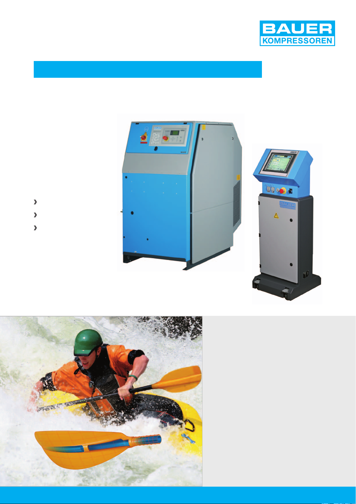
GAS INJECTION TECHNOLOGY – GIT
Innovative and complete solutions
ECONOMICAL
MODULAR
RELIABLE
www.bauer-kompressoren.de
BAUER KOMPRESSOREN
offer Gas Injection Technology
as a solution to the problems
of plastic part production.
The end user will benefit from
BAUER’s years of manufacturing
experience in the field of GIT and
compressor technology with tailormade systems from one source.
Bauer offer starter packs to complex
large-scale systems.
For a perfect system design, the
BAUER team is available and willing
to provide on site advice.
Page 2
GIT-SYSTEMSBAUER KOMPRESSOREN
GIT technology from BAUER - solutions from one source
BRIEF OVERVIEW OF GIT TECHNOLOGY
A procedure similar to GIT was described for the
first time in 1972. This technology has a proven
reliability and market growth from the 1980’s.
We denote by GIT, the method of blowing gas,
especially nitrogen in the plastic, so that a hollow
tubular channel is created.
Previously, the plastic had been melted and injected
into a mould, which for thick pieces of plate, it was not
possible to produce a flattened bubble.
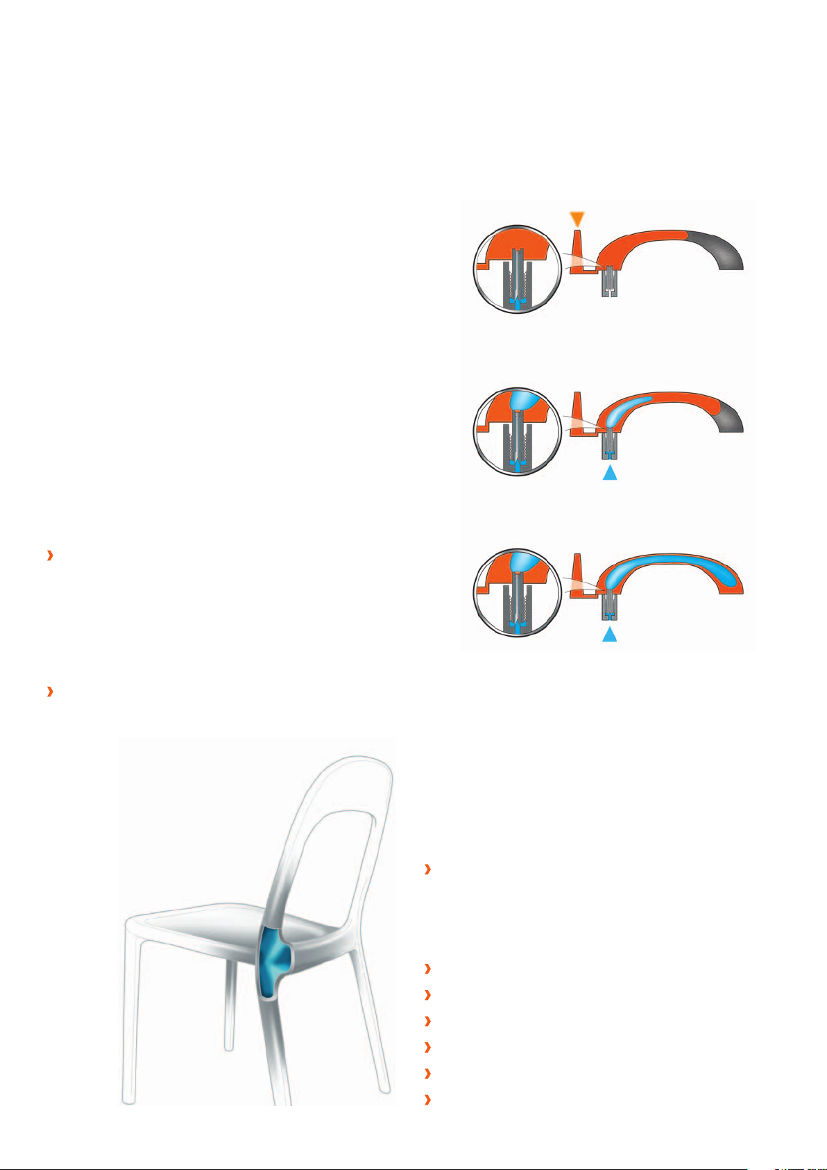
THE DIFFERENT TECHNIQUES
There are at least 10 variants of GIT, based on
the type of piece produced and its needs. The
two most commonly used techniques are briefly
explained as follows:
The partial original method, which is to fill 50-90%
of the cavity with plastic. By moving the mass of hot
plastic, the gas can finish filling 100% while creating
a hollow tubular channel. The holding phase under
pressure during the cooling phase is carried by the
gas, whose pressure drop just before opening
the mould.
Plastic
1
2
Gas
3
Gas
The over flow cavity, which requires the addition of
an annex cavity in the tool. After filling the part
cavity at 100% with polymer, the gas is injected
under pressure and the overflow cavity is
open to collect the superfluous plastic.
The gas ensures the holding phase
pressure during cooling and is
purged immediately
before opening
the mould.
BENEFITS OF GIT
The use of gas assisted injection technology
allows production of technical parts with
the appearance of superior quality. The
manufacturing process is also more efficient,
improving productivity and thus significantly
increasing profitability.
A better quality of injected part:
- High strength and rigidity
- Dimensional stability, no warpage
- Elimination of sink marks
- No assembly, single parts
Simplification of tools
Freedom in design
Lower clamping force (in partial)
Reduced cycle time
Material saving
Realization of hollow (pipe)
Page 3
GIT-SYSTEMS
BAUER EXPERIENCE
Our outstanding expertise in purifying gases
coupled with software-based control technology developed by our BAUER specialists
guarantee you outstanding product quality
which will improve profitability.
HIGH PRESSURE COMPRESSOR
AND BOOSTER UNITS
Ready for use; compact and autonomous.
A compression of high quality nitrogen thanks
to our P-filter system.
Booster units with low power consumption by
using the inlet pressure of a nitrogen generator
or evaporator.
A security operation through an integrated
controller (B-CONTROL).
FCC CONTROL UNIT
A mobile and compact panel.
An adaptive control and therefore very precise
(reactivity adjustable).
Easy and intuitive programming.
A full connectivity to transfer files (USB and Ethernet).
Continuous process monitoring with quality data
storage.
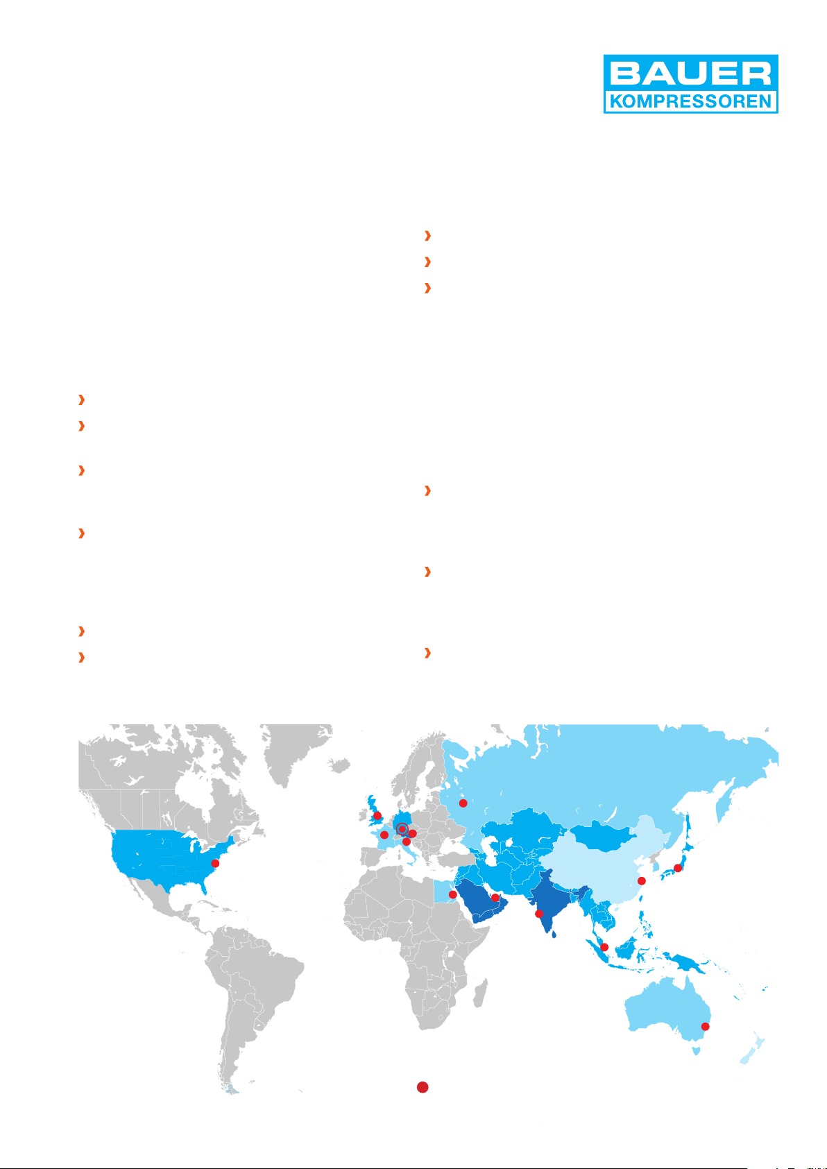
EXCELLENT SERVICE GUARANTEED
For BAUER, „quality“ does not end with the production and delivery of the system. Independent
of the location of the installation, the customer
benefits from the excellent and comprehensive
after sales service support:
All major spare parts, including wearing parts, for all
models are permanently in stock, and available for
immediate dispatch. Parts are guaranteed to be
available for up to 25 years after delivery.
An integrated distribution network comprising of
over 50 overseas agencies, plus 360 support
distributors are continually available to support
our customers.
Maintenance kits for all systems are available
worldwide.
BAUER daughter companies worldwide
Page 4
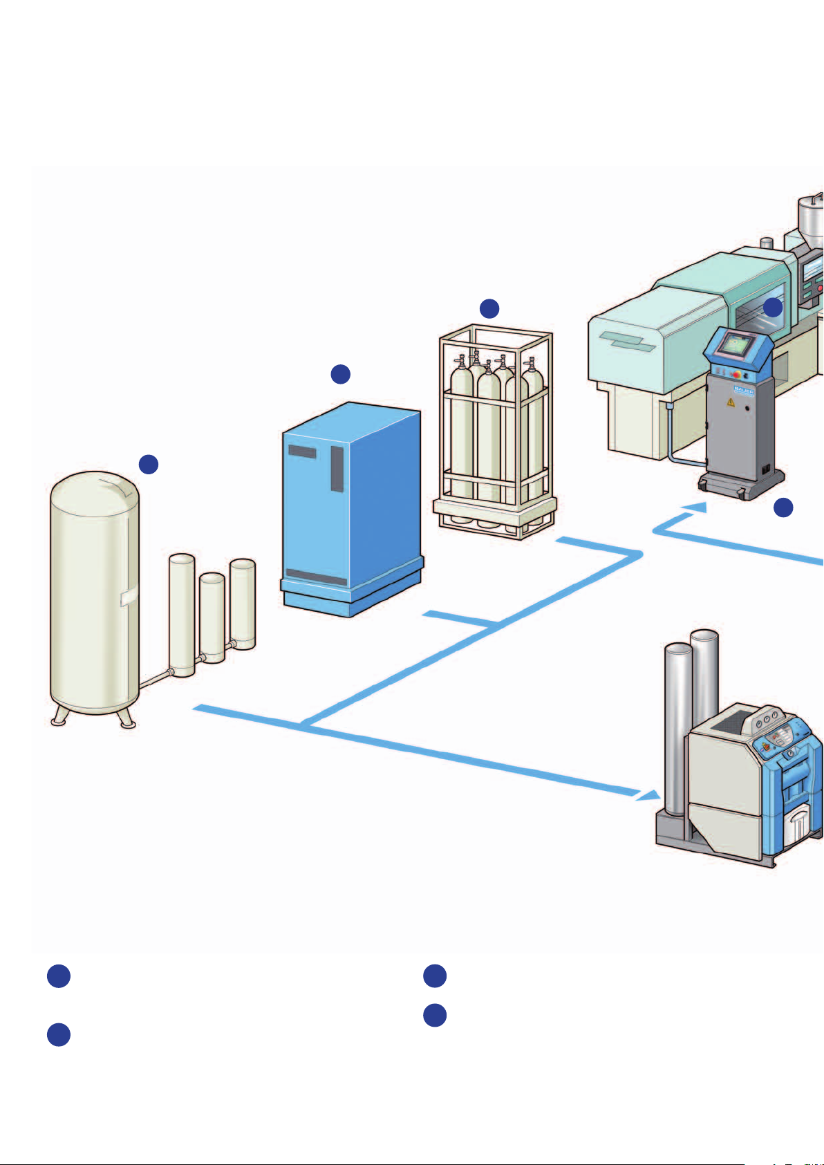
GIT-SYSTEMSBAUER KOMPRESSOREN
Structure of the system
System requirements: The following equipment is required to employ gas injection technology
in your process.
1
1
1
1
1
1
1
1
5
5
5
5
1
1
1
1
4
4
4
4
1
Source of nitrogen: Liquid tank, nitrogen
bottles or nitrogen generator.
2
A high pressure compressor with a suitably
sized gas receiver facility for the compression
and safe storage of nitrogen at high pressures.
3
High pressure lines to transport the nitrogen.
4
Distribution panel that generates a pressure- /
time profile to dispense the nitrogen.
Page 5

GIT-SYSTEMS
5
5
5
5
5
5
5
5
6
6
6
6
7
7
7
4
4
4
4
4
4
4
4
8
8
8
8
3
3
3
3
2
2
2
2
7
5
Gas injectors to fill nitrogen into the plastic
parts for hollowing.
Bypass valve available to prevent the
6
ingress of dirt into the proportional
regulating valve.
7
Flushing Module FM1 assures quick cooling,
which it turn reduces the cycle times.
8
Mass flow meter MF II for exact measurement of the nitrogen consumption.
Page 6

GIT-SYSTEMSBAUER KOMPRESSOREN
Product range for nitrogen compression
Wherever high pressure nitrogen needs to be generated in a confined space providing economically efficient continuous and autonomously nitrogen supply, BAUER high pressure compressors
and booster will perform the task quietly and reliably to meet the demands of one or multiple
injection moulding machines.
THE MINI-VERTICUS III-RANGE
Soundproof and compact
The perfect unit for confined areas in industrial
applications – available as a compressor with
atmospheric or booster inlet conditions.
Multi stage piston compressor units, lubricated,
soundproof <70 dB (A), with a final separator
and filtration system P61 type for securing a
compressed gas with high purity.
Complete system mounted on skid with up to
two HP cylinders, compact and limited to small
compressor block range.
Directly connectable to the source of nitrogen.
Designed for long life and low operating costs.
Model
350 bar / 5000 psig, High pressure compressor for nitrogen
MV-GI 100-3-3 85 5 3 900 3 2,2 255
MV-GI 100-4-3 125 7,5 3 1270 4 3,1 255
MV-GI 120-4-3 170 10 3 1200 4 3,7 260
MV-GI 120-5,5-3 215 13 3 1470 5,5 4,7 260
1)
F.A.D.
l/min m
Number
of stages
3
/h r.p.m kW kW kg
Speed Motor
power
Power
consumption
Net weight
approx.
Model
350 bar / 5000 psig, High pressure booster for nitrogen
MV-GIB 12.2-5,5-3 200-475
1) Measured acc. to ISO 1217.
1)
F.A.D.
l/min m
2)
12-28,5 2 5-11 90-350 1230 5,5 3,3-5,1 275
Number
of stages
3
/h (bar g) bar r.p.m kW kW kg
Intake
pressure
Operating
pressure
2) Maximum capacity according to the
combination of intake and final pressure.
Speed Motor
power
Power
consumption
Net weight
approx.
Page 7

GIT-SYSTEMS
THE VERTICUS 5 RANGE
The high pressure compression under control.
Multi stage piston compressor/booster units,
lubricated, with a final separator and filtration
type P61 / P81 for securing a compressed gas
with high purity.
Complete system mounted on skid with up to
two HP cylinders.
Available as soundproof version 72-76 dB(A).
Directly connectable to the source of nitrogen.
The B-CONTROL controller allows to monitor
the operation of the compressor and to
indicate the alarms such as temperatures,
operating pressures, oil pressure and
maintenance, etc.
500 bar discharge pressure version optional.
Model
GI - Range, 90 - 350 bar / 1300 - 5000 psig
GI 100-3-5 85 5,1 3 900 3 2,2 335
GI 100-4-5 125 7,5 3 1270 4 3,3 340
GI 120-5,5-5 215 13 3 1470 5,5 4,7 355
GI 15.1-7,5-5 340 20,4 4 1050 7,5 6,9 440
GI 15.1-11-5 420 25,2 4 1320 11 9,6 450
GI 150-11-5 500 30 4 1230 11 10,2 460
GI 180-15-5 610 36,6 4 1320 15 12 470
GI - Range, 350 - 500 bar / 5000 - 7200 psig
GI 15.11-7,5-5 310 18 ,6 4 960 7,5 7 470
GI 15.11-11-5 420 25,2 4 1320 11 10,4 470
GI 18.1-15-5 550 33 5 1320 15 12,4 470
Model
Intake
pressure
bar(g) l/min m
BOOSTER GIB, 90-350 bar / 1300-5000 psig
GIB 12.2-5,5-5 5 - 11 200 - 475
GIB 15.3-11-5 7 - 10 510 - 750
GI B 15.4-15-5 2 - 4 450 - 800
1)
F.A.D
l/min m
Number
of stages
3
/h r.p.m. kW kW kg
1)
F.A.D.
2)
12 - 28,5 2 1230 3,3 - 5,3
2)
30,6 - 45 2 114 0 6,6 - 8,2
2)
27 - 48 3 1320 7,6 - 12,2
Speed Motor Power
consumption
Number
of stages
3
/h r.p.m. kW
Speed Power
consumption
Net weight
approx.
1) Measured acc. to ISO 1217.
2) Maximum capacity according to the
combination of intake and final pressure.
Page 8

GIT-SYSTEMSBAUER KOMPRESSOREN
The FCC 5 - the latest first-class controller
THE DISTRIBUTION PANEL
BAUER distribution panels have been in operation worldwide for the past 10 years. These mature
and well proven control systems guarantee the user maximum reliability, with minimum downtime.
INTERFACE AND CONTROLLER
Seven levels of time pressure with ramps
transition in time.
Password protection (3 profiles).
Cleaning cycle with clogged injector
detection (patented).
Graphic displays for pressure versus time.
Screen quality on the relevant current
values and last 100 cycles.
Alarms (message, sound 97 dB, cycle stopped)
with history.
Programs and data quality storage on
internal memory Compact Flash, USB key
or via Ethernet.
Screen service with maintenance history
and display technician diagnostic.
Support and diagnosis via the Internet in
real time.
Usage with 2 moulding machines
possible (option).
CONNECTIONS
Start signal: screw position or the start of
plastic injection.
Compatible with all injection moulding
machines including EUROMAP 62 standard.
Page 9

GIT-SYSTEMS
All informations at a glance!
The high resolution touch screen shows all relevant parameters. It provides clear user guidance
and allows a comprehensive range of settings for controlling and monitoring the process.
Time/pressure levels can be easily programmed.
Various alarm settings can be selected by the user.
REGULATING MODULE
Built as a modular construction, the valve
module can be mounted separately from the
distribution panel, or near to the mould.
The set-actual graph informs about the process quality.
Alarms messages on the last 1000 events
Electrical proportional regulating valve.
High reproducibility of parts guaranteed.
High precision from 5 to 400 bar.
1 to 4 proportional valves, exchangeable
and also available for retrofit.
1-2 proportional valves per valve module.
Integrated filtration of 25 µm.
Low maintenance costs with fast service support.
Page 10

The new Flushing Module FM I
The flushing module FM I accelerates the
cooling of the mould by up to 50%, thus
decreasing the cycle time of GIT parts.
Two injectors are needed to flush, one
at each end.
Initially, an injector introduces nitrogen, as
found in the classical GIT process. Then pressure
is switched on the second injector to break into
the first bubble and to achieve a leakage rate
through the first injector.
This movement generates heat exchange by
forced convection inside the part in the hottest
zone. This is considerably more effective than
conduction through the mould with a mass of
highly insulating plastic.
GIT-SYSTEMSBAUER KOMPRESSOREN
The FM I can be easily integrated into an existing
process that requires only the installation
of a second gas injector. The flushing module
is driven directly by the panel of gas
assisted injection.
Additional cooling of the flushing gas is not
necessary!
Data line
Flushing module FM1
cooling
down
feed line
N
2
injection
N
2
N
flushing
2
Page 11

GIT-SYSTEMS
Keep it simple –
our economically priced starter pack
LCC I – LIGHT CLASS CONTROLLER
Equipped with 1 or 2 valves, this small distribution panel is programmed via an external laptop.
The LCC I can be directly mounted on the injection moulding machine, which minimizes the
nitrogen consumption.
INTERFACE AND PLC
Programmed via an external laptop which can
be removed during production.
Five time and pressure stages with ramp
transitions in time.
Quality and alarms screens are available.
Remote control for Start/Stop, Injector test,
Reset IP address functions. Green and
red lights inform on panel status (ready,
cycle in progress, alarms, etc.).
Programs and quality data storage on
internal memory Compact Flash.
CONNECTION
Start signal: start of plastic injection.
Compatible with all injection moulding machines
including EUROMAP 62 standard.
Ethernet port on remote control to
connect a laptop.
LCC I, with remote control and optional laptop
Page 12

GIT-SYSTEMS
PRODUCT SERVICE
DIN EN ISO 9001
The GIT technology accessory range
GAS INJECTORS
The stainless steel injectors can be
used for all gas injection processes.
No penetration of melt.
Diameter: 2 – 12 mm.
Quick and easy cleaning.
Optional with seal.
Specific size on demand.
BAUER gas injectors
BYPASS VALVE
The bypass valve has to be placed between
the mould and the distribution panel.
Protects the valve module from from plastic
degassing pollution.
No external energy needed.
Increases the system availability.
MF II FLOW METER
Patented system optional on FCC 5
Allow to follow nitrogen consumption and to
control the process repeatability.
This flow meter and its interface are completely
integrated to the panel FCC 5 (alarms, graphic,
quality and statistic screens).
Bypass valve
For 1- 4 channels.
BAUER KOMPRESSOREN GmbH
P.O. Box 710260 | 81452 München
Phone +49 (0) 89 / 7 80 49 - 0
Fax +49 (0) 89 / 7 80 49 - 167
industry@bauer-kompressoren.de
www.bauer-kompressoren.de
MF II flow meter
GIT-E
10.10 PR 0094
Subject to technical modifications
 Loading...