

Page 1
Wireless 802.11 b/g/n ADSL2+ Router User’s Guide
Wireless 802.11
b/g/n ADSL2+
Router
User’s Manual
1
Page 2

Wireless 802.11 b/g/n ADSL2+ Router User’s Guide
Table of Contents
1 Introduction..........................................................9
Features ................................................................................9
Device Requirements ...........................................................9
Using this Document...........................................................10
Notational conventions ................................................10
Typographical conventions ..........................................10
Special messages........................................................10
Getting Support ...................................................................10
2 Getting to know the device................................11
Computer / System requirements ......................................11
Package Contents ..............................................................11
For Annex-B 802.11n WLAN ADSL2+
Router .......................................................................11
For Annex-A 802.11n WLAN ADSL2+
Router .......................................................................11
Installation & Setup .............................................................12
LED meanings & activations ..............................................14
Back Panel Connectors ...............................................15
3 Computer configurations under
different OS, to obtain IP address
automatically...................................................17
4 Utility CD execution ...........................................25
Connecting the Hardware...................................................25
Wireless Connection ...........................................................31
5 Getting Started with the Web pages .................33
Accessing the Web pages ..................................................33
Testing your Setup..............................................................36
Default device settings........................................................36
6 Overview ...........................................................39
Internet access settings ......................................................41
About Wireless ADSL2+ Router.........................................41
7 Status ................................................................42
Device Info ..........................................................................42
ADSL ...................................................................................44
Statistics ..............................................................................45
8 Internet Access..................................................46
Types of Internet Access ....................................................47
2
Page 3

Wireless 802.11 b/g/n ADSL2+ Router User’s Guide
Configuring your PPPoE DSL connection .........................48
Configuring your PPPoA DSL connection .........................50
Configuring your Bridged DSL connection.........................52
Configuring your 1483 MER by DHCP ..............................53
Configuring your 1483 MER by Fixed IP ...........................54
ATM Settings.......................................................................55
ADSL Settings.....................................................................57
9 Local Network Configuration.............................59
Changing the LAN IP address and subnet
mask ................................................................................59
Adding the Secondary LAN IP address and
subnet mask ....................................................................64
10 DHCP Settings ..................................................65
DHCP Server Configuration ...............................................65
DHCP Relay Configuration.................................................67
DHCP None Configuration .................................................69
11 DHCP Static Configuration................................70
DHCP Static Configuration.................................................70
12 LAN IPv6 Configuration.....................................71
DHCP Static Configuration.................................................71
13 Wireless Network ..............................................72
Basic Settings .....................................................................72
Security................................................................................74
WEP + Encryption Key ................................................76
WEP + Use 802.1x Authentication..............................77
WPA/WPA2/WPA2 Mixed + Personal
(Pre-Shared Key)......................................................77
WPA/WPA2/WPA2 Mixed + Enterprise
(RADIUS)..................................................................79
Wireless Multiple BSSID Settings ......................................80
Access Control....................................................................82
Allow Listed ..................................................................83
Deny Listed ..................................................................83
Advanced Settings ..............................................................85
WPS ....................................................................................88
Introduction of WPS .....................................................88
Supported WPS features.............................................88
AP mode.......................................................................89
AP as Enrollee .............................................................89
AP as Registrar ............................................................89
3
Page 4

Wireless 802.11 b/g/n ADSL2+ Router User’s Guide
AP as Proxy .................................................................89
Infrastructure-Client mode ...........................................89
Instructions of AP’s and Client’s
operations .................................................................90
Operations of AP - AP being an enrollee ...........................92
Operations of AP - AP being a registrar...........................103
AP mode.....................................................................103
Push Button method ..................................................107
14 Routing ............................................................111
Static Route.......................................................................111
IPv6 Static Route ..............................................................113
RIP.....................................................................................114
15 DMZ.................................................................116
Configuring DMZ...............................................................116
16 Virtual Server...................................................118
Configuring Virtual Server.................................................118
Configuring custom applications ......................................119
Virtual Server for FTP................................................120
Port Forwarding for HTTP .........................................123
Deleting custom applications .....................................126
17 NAT Forwarding ..............................................127
Configuring NAT Forwarding............................................127
18 ALG .................................................................128
Configuring ALG ...............................................................128
19 NAT Exclude IP...............................................129
Configuring NAT Exclude IP.............................................129
20 Port Trigger .....................................................130
Configuring Port Trigger ...................................................130
21 FTP ALG Portl.................................................131
Configuring Port Trigger ...................................................131
22 Nat IP Mapping................................................132
Configuring Port Trigger ...................................................132
23 IP QoS.............................................................133
IP QoS...............................................................................133
24 CWMP Config .................................................135
CWMP Configuration........................................................135
25 Port Mapping...................................................137
Port Mapping.....................................................................137
4
Page 5

Wireless 802.11 b/g/n ADSL2+ Router User’s Guide
26 Bridging ...........................................................140
Bridging .............................................................................140
27 Client Limit.......................................................141
Client Limit.........................................................................141
28 Tunnel Configuration.......................................142
Tunnel Configuration ........................................................142
29 Others..............................................................143
Others................................................................................143
30 IGMP Proxy.....................................................144
IGMP Proxy.......................................................................144
31 UPnP ...............................................................145
Configuring UPnP .............................................................146
UPnP Control Point Software on Windows
ME..................................................................................147
UPnP Control Point Software on Windows
XP with Firewall .............................................................147
SSDP requirements ...................................................148
32 SNMP ..............................................................151
SNMP ................................................................................151
33 DNS Configuration ..........................................152
DHCP Server Configuration - Attain DNS
Automatically .................................................................152
DHCP Server Configuration - Set DNS
Manually.........................................................................153
IPv6 DNS...........................................................................154
34 Dynamic DNS Configuration ...........................155
Overview of Dynamic DNS ...............................................155
Dynamic DNS Configuration – DynDNS.org ...................157
Dynamic DNS Configuration – TZO.................................159
35 MAC Filtering...................................................161
Configuring MAC filtering to Deny for
outgoing access.............................................................161
36 IP/Port Filtering................................................163
IP/Port Filtering..................................................................163
37 URL Filter ........................................................165
Configuring URL Blocking of Keyword.............................165
38 ACL Configuration...........................................167
ACL Config........................................................................167
39 DoS .................................................................168
DoS Config........................................................................168
5
Page 6

Wireless 802.11 b/g/n ADSL2+ Router User’s Guide
40 Firmware Update.............................................169
About firmware versions ...................................................169
Manually updating firmware..............................................169
41 Backup/Restore...............................................173
Backup settings.................................................................173
Restore settings ................................................................174
42 Password.........................................................175
Setting your username and password .............................175
43 Commit/Reboot ...............................................177
Commit ..............................................................................177
Reboot...............................................................................178
Resetting to Defaults.........................................................178
44 Time Zone .......................................................180
SNTP Server and SNTP Client
Configuration settings....................................................180
45 Log...................................................................186
Log.....................................................................................186
46 Diagnostic........................................................187
Ping ...................................................................................187
Ping6 .................................................................................188
Tracert ...............................................................................189
OAM Loopback .................................................................189
ADSL Diagnostic...............................................................191
Diagnostic Test .................................................................192
A Configuring your Computers ...........................195
Configuring Ethernet PCs.................................................195
Before you begin........................................................195
Windows® XP PCs....................................................195
Windows 2000 PCs ...................................................195
Windows Me PCs ......................................................197
Windows 95, 98 PCs .................................................197
Windows NT 4.0 workstations ...................................198
Assigning static Internet information to
your PCs .................................................................199
B IP Addresses, Network Masks, and
Subnets ........................................................200
IP Addresses.....................................................................200
Structure of an IP address .........................................200
Network classes.........................................................200
6
Page 7

Wireless 802.11 b/g/n ADSL2+ Router User’s Guide
Subnet masks ...................................................................201
C Troubleshooting...............................................203
Troubleshooting Suggestions ...........................................203
Diagnosing Problem using IP Utilities ..............................205
ping.............................................................................205
nslookup .....................................................................206
D Glossary ..........................................................207
7
Page 8

Wireless 802.11 b/g/n ADSL2+ Router User’s Guide
Notice
This device complies with Part 15 of the FCC Rules. Operation is subject to the
following two
conditions: (1) this device may not cause harmful interference and (2) this device
must accept any
interference received, including interference that may cause undesired operation.
For P15B equipment
This equipment has been tested and found to comply with the limits for a Class B
digital device,
pursuant to part 15 of the FCC rules. These limits are designed to provide
reasonable protection
against harmful interference in a residential installation. This equipment generates,
uses and can
radiate radio frequency energy and, if not installed and used in accordance with the
instructions, may
cause harmful interference to radio communications. However, there is no
guarantee that interference
will not occur in a particular installation. If this equipment does cause harmful
interference to
radio or television reception, which can be determined by turning the equipment off
and on, the user
is encouraged to try to correct the interference by one or more of the following
measures:
-Reorient or relocate the receiving antenna.
-Increase the separation between the equipment and receiver.
-Connect the equipment into an outlet on a circuit different from that to which the
receiver is
connected.
-Consult the dealer or an experienced radio/TV technician for help.
For mobile devices
FCC RF Radiation Exposure Statement:
1. This Transmitter must not be co-located or operating in conjunction with any
other antenna or
transmitter.
2. This device complies with FCC radiation exposure limits set forth for an
uncontrolled environment. In order to avoid the possibility of exceeding the FCC
radio frequency exposure limits, human proximity to the antenna shall not be less
than 20cm (8inches) during normal operation.
8
Page 9

Wireless 802.11 b/g/n ADSL2+ Router User’s Guide
1 Introduction
Congratulations on becoming the owner of the Wireless
ADSL2+ Router. You will now be able to access the Internet
using your high-speed DSL connection.
This User Guide will show you how to connect your Wireless
ADSL2+ Router, and how to customize its configuration to
get the most out of your new product.
Features
The list below contains the main features of the device and
may be useful to users with knowledge of networking
protocols. If you are not an experienced user, the chapters
throughout this guide will provide you with enough
information to get the most out of your device.
Features include:
• Internal DSL modem for high-speed Internet access
• 10/100Base-T Ethernet Router to provide Internet
connectivity to all computers on your LAN
• Network address translation (NAT) functions to provide
security for your LAN
• Network configuration through DHCP Server and DHCP
Client
• Services including IP route and DNS configuration, RIP, and
IP and DSL performance monitoring
• User-friendly configuration program accessed via a web
browser
• User-friendly configuration program accessed via EasySetup
program
Device Requirements
In order to use the Wireless ADSL2+ Router, you must have
the following:
• DSL service up and running on your telephone line
• Instructions from your ISP on what type of Internet
access you will be using, and the addresses needed to set
up access
• One or more computers each containing an Ethernet
card (10Base-T/100Base-T network interface card (NIC))
• For system configuration using the supplied
a. web-based program: a web browser such as Internet
Explorer v4 or later, or Netscape v4 or later. Note that version
4 of each browser is the minimum version requirement – for
optimum display quality, use Internet Explorer v5, or
Netscape v6.1
b. EasySetup program: Graphical User Interface
9
Page 10
Wireless 802.11 b/g/n ADSL2+ Router User’s Guide
You do not need to use a hub or switch in order to connect more
Note
than one Ethernet PC to your device. Instead, you can connect
up to four Ethernet PCs dire ctly to you r devi ce using t he po rts
labeled Ethernet on the rear panel.
Using this Document
Notational conventions
• Acronyms are defined the first time they appear in the
text and also in the glossary.
• For brevity, the Wireless ADSL2+ Router is referred to as
“the device”.
• The term LAN refers to a group of Ethernet-connected
computers at one site.
Typographical conventi ons
• Italic text is used for items you select from menus and
drop-down lists and the names of displayed web pages.
• Bold text is used for text strings that you type when
prompted by the program, and to emphasize important
points.
Special messages
This document uses the following icons to draw your
attention to specific instructions or explanations.
Note
Provides clarifying or non-essential information on the current
topic.
Definition
Explains terms or acronyms that may be unfamiliar to many
readers. These terms are also included in the Glossary.
Provides messages of high importance, including messages
relating to personal safety or system integrity.
WARNING
Getting Support
Supplied by:
Helpdesk Number:
Website:
10
Page 11

Wireless 802.11 b/g/n ADSL2+ Router User’s Guide
2 Getting to know the device
Computer / System requirements
• 1. Pentium 200MHZ processor or above
• 2. Windows 98SE, Windows Me, Windows 2000, Windows
XP, Windows Vista and Windows 7
• 3. 64MB of RAM or above
• 4. 25MB free disk space
Package Contents
For Annex-B 802.11n WLAN ADS L2+ Router
• 1. 802.11n WLAN ADSL2+ Router
• 2. CD-ROM (Software & Manual)
• 3. Quick Installation Guide
• 4. 1 x Telephone Cable (RJ-11)
• 5. Ethernet Cable (RJ-45)
• 6. Power Adaptor
• 7. Annex-B Splitter (Optional, with an extra RJ-11
Telephone cable)
For Annex-A 802.11n WLAN ADS L2+ Router
• 1. 802.11n WLAN ADSL2+ Router
• 2. CD-ROM (Software & Manual)
• 3. Quick Installation Guide
• 4. 1 x Telephone Cable (RJ-11)
• 5. Ethernet Cable (RJ-45)
• 6. Power Adaptor
• 7. Annex-A Splitter (Optional, with an extra RJ-11
Telephone cable)
11
Page 12
Wireless 802.11 b/g/n ADSL2+ Router User’s Guide
Installation & Setup
Follow each STEP carefully and only go to the next step once you have complete the
previous STEP.
Connection of 802.11n WLAN ADSL2+ Router
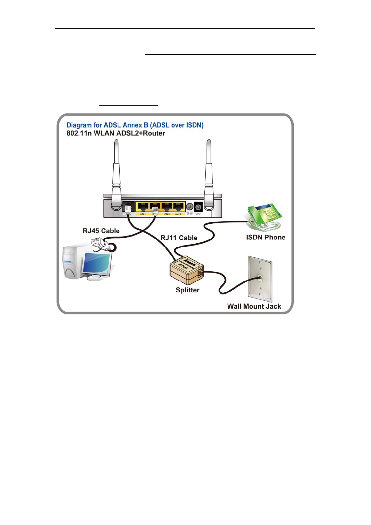
If you have an ISDN telephone line
connect the modem router as shown below:
1. Connect the supplied RJ45 Ethernet cable from your PC's Ethernet port to any of the 4
802.11n WLAN ADSL2+ Router's LAN Ports.
2. Connect the supplied RJ11 telephone cable from your home's telephone jack to the
“LINE” port of the supplied splitter. Connect another RJ11 telephone cable to the
“MODEM” port of the splitter and connect the other end of this cable to the LINE port of
your 802.11n WLAN ADSL2+ Router.
supplied RJ11 telephone cable from your home's telephone jack to the “LINE” port of your
802.11n WLAN ADSL2+ Router.)
3. Connect a RJ11 telephone cable to the “PHONE” port of the splitter and connect the other
end to your telephone.
4. Connect the power adapter to the power inlet “POWER” of the 802.11n WLAN ADSL2+
Router and turn the “ON/OFF SWITCH” switch of your 802.11n WLAN ADSL2+ Router on.
(If there is no option Splitter, please connect the
12
Page 13
Wireless 802.11 b/g/n ADSL2+ Router User’s Guide
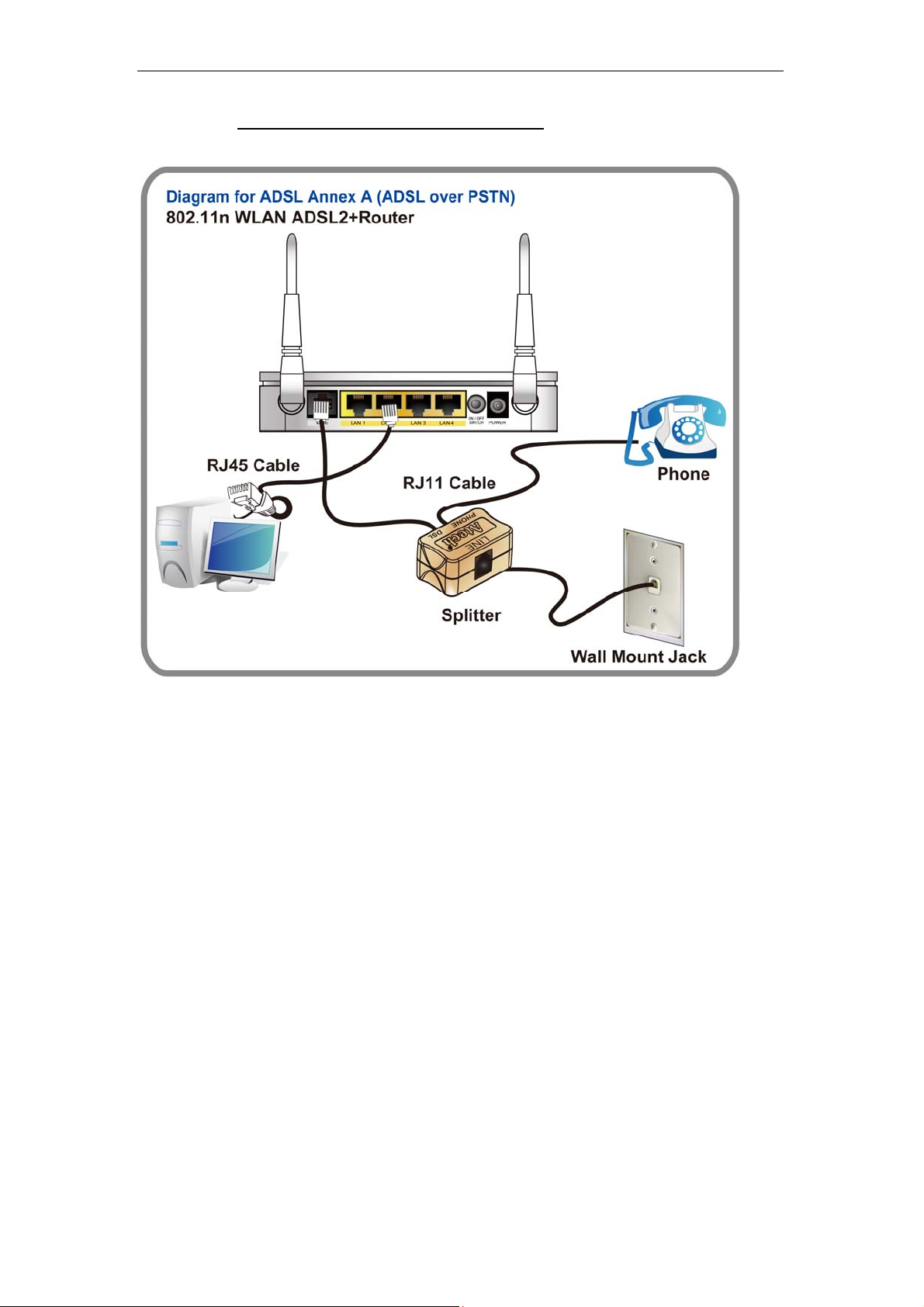
If you have a PSTN telephone line (normal analog line) connect the router as shown
below:
1. Connect the supplied RJ45 Ethernet cable from your PC's Ethernet port to any of the 4
802.11n WLAN ADSL2+ Router's LAN Ports.
2. Connect the supplied RJ11 telephone cable from your home's telephone jack to the
“LINE” port of the supplied splitter. Connect the other supplied RJ11 telephone cable to
the “DSL” port of the splitter and connect the other end of this cable to the “LINE” port of
your 802.11n WLAN ADSL2+ Router. (If there is no option Splitter, please connect the
supplied RJ11 telephone cable from your home's telephone jack to the “LINE” port of your
802.11n WLAN ADSL2+ Router.)
3. Connect a RJ11 telephone cable to the “PHONE” port of the splitter and connect the other
end to your telephone.
4. Connect the power adapter to the power inlet “POWER” of the 802.11n WLAN ADSL2+
Router and turn the “ON/OFF SWITCH” switch of your 802.11n WLAN ADSL2+ Router on.
13
Page 14

Wireless 802.11 b/g/n ADSL2+ Router User’s Guide
LED meanings & activations
Your 802.11n WLAN ADSL2+ Router has indicator lights on the
front side. Please see below for an explanation of the function of
each indicator light.
Power indicator
Ethernet Active indicator
Wireless Active indicator
Table1. LED function
Label Color On Flash Off
Red Device malfunction Waiting for device ready N/A
Green Ready Waiting for device ready Power Off
Internet Active indicator
WPS Active indicator
ADSL Link indicator
Green Ethernet Connected Transmit / Receive Data Ethernet
Green WLAN Ready Transmit / Receive Data WLAN Off
Green Connect to DSLAM Disconnect to DSLAM N/A
Green The device has a WAN IP
Red No WAN IP address from ISP N/A N/A
Green N/A Start WPS peer within 2
address from ISP
The icons appear on the products are for application indication
only.
The trademark or intellectual property is belonging to their
respective owners.
Transmit / Receive Data N/A
minutes
Disconnected
WPS Idle
14
Page 15
Wireless 802.11 b/g/n ADSL2+ Router User’s Guide
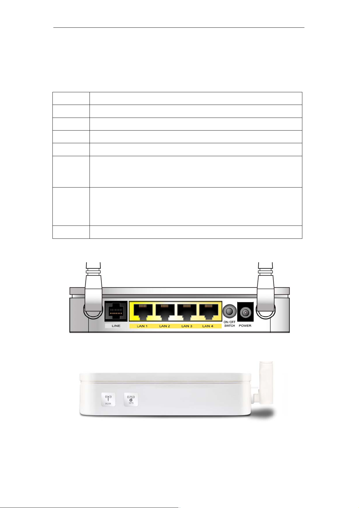
Back Panel Connectors
Table 2 shows the function of each connector and switch of the device.
Table 2. Function / Description of Connectors
Connector Description
POWER
SWITCH
LAN1~4
LINE
RESET
WPS
WLAN
Connects to your 802.11n WLAN ADSL2+ router 12Vac power adaptor
Power Switch
RJ-45 Jack (Ethernet Cable) connection to your PC, or HUB
Connects to your ADSL2+ line – for ADSL2+ Line input
Reset button. RESET the 802.11n WLAN ADSL2+ router to its default
settings.
Press this button for at least 5 full seconds to start to reset it to its default
settings.
Press this button for at least 3 full seconds and the WPS LED will flash to
start WPS.
Now go to the wireless adapter or device and press its WPS button. Make
sure to press the button within 120 seconds (2 minutes) after pressing the
router's WPS button.
Press this button for at least 3 full second to turn off/on wireless signals
Figure1. Rear View of the 802.11n WLAN ADSL2+ Router
Figure2. WPS and WLAN button
15
Page 16

Wireless 802.11 b/g/n ADSL2+ Router User’s Guide
Figure3. RESET button
16
Page 17
Wireless 802.11 b/g/n ADSL2+ Router User’s Guide
3 Computer configurations under different OS,
to obtain IP address automatically
Before starting the 802.11n WLAN ADSL2+ Router
configuration, please kindly configure the PC computer as
below, to have automatic IP address / DNS Server.
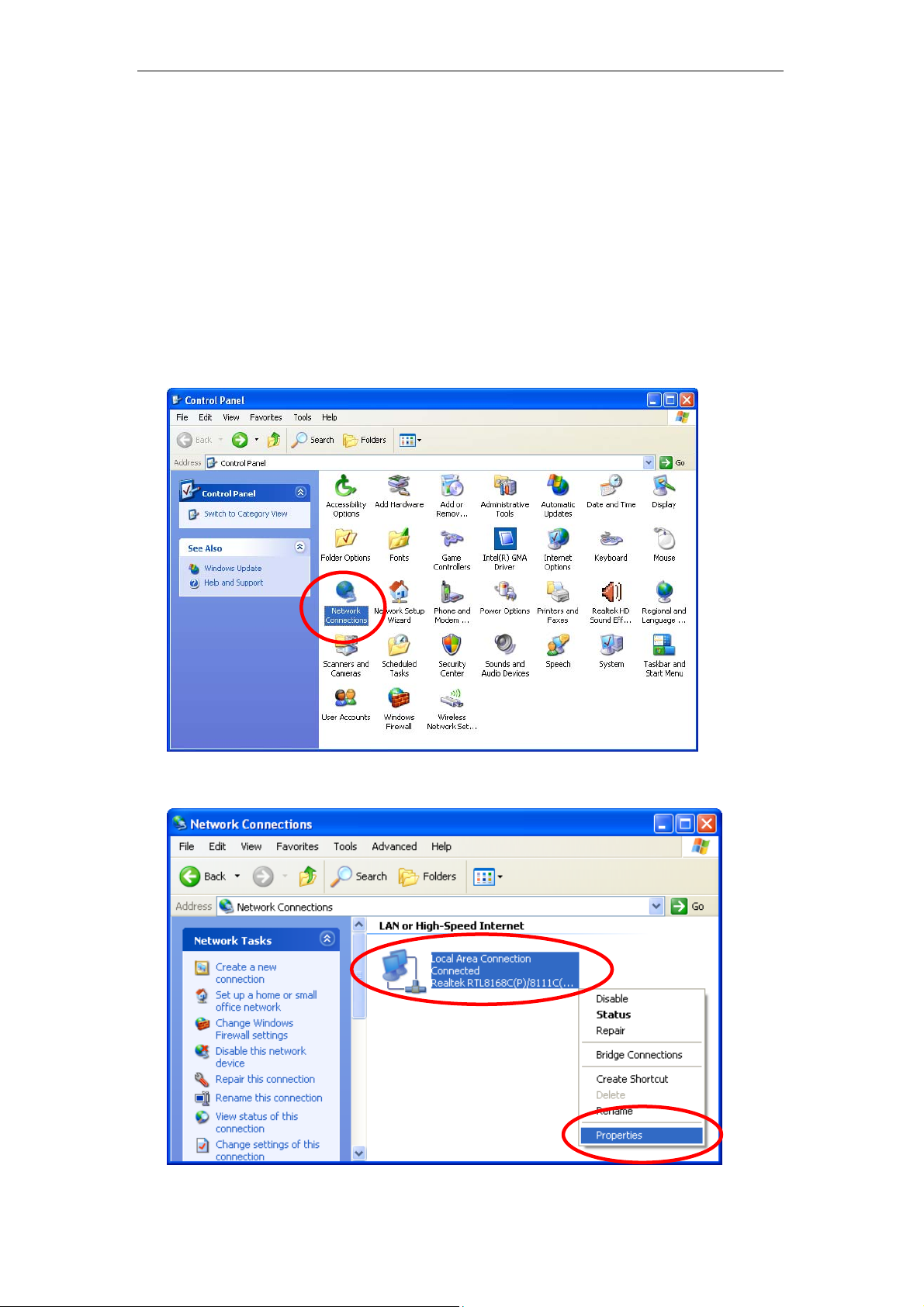
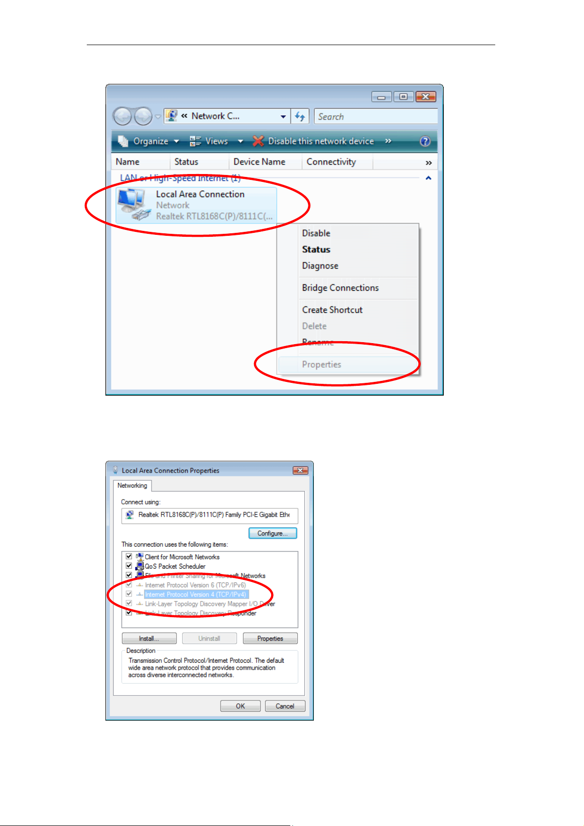
For Windows 98SE / ME / 2000 / XP
1. Click on “Start” -> “Control Panel” (in Classic View). In the Control Panel,
double click on “Network Connections” to continue.
2. Single RIGHT click on “Local Area connection”, then click “Properties”.
17
Page 18
Wireless 802.11 b/g/n ADSL2+ Router User’s Guide
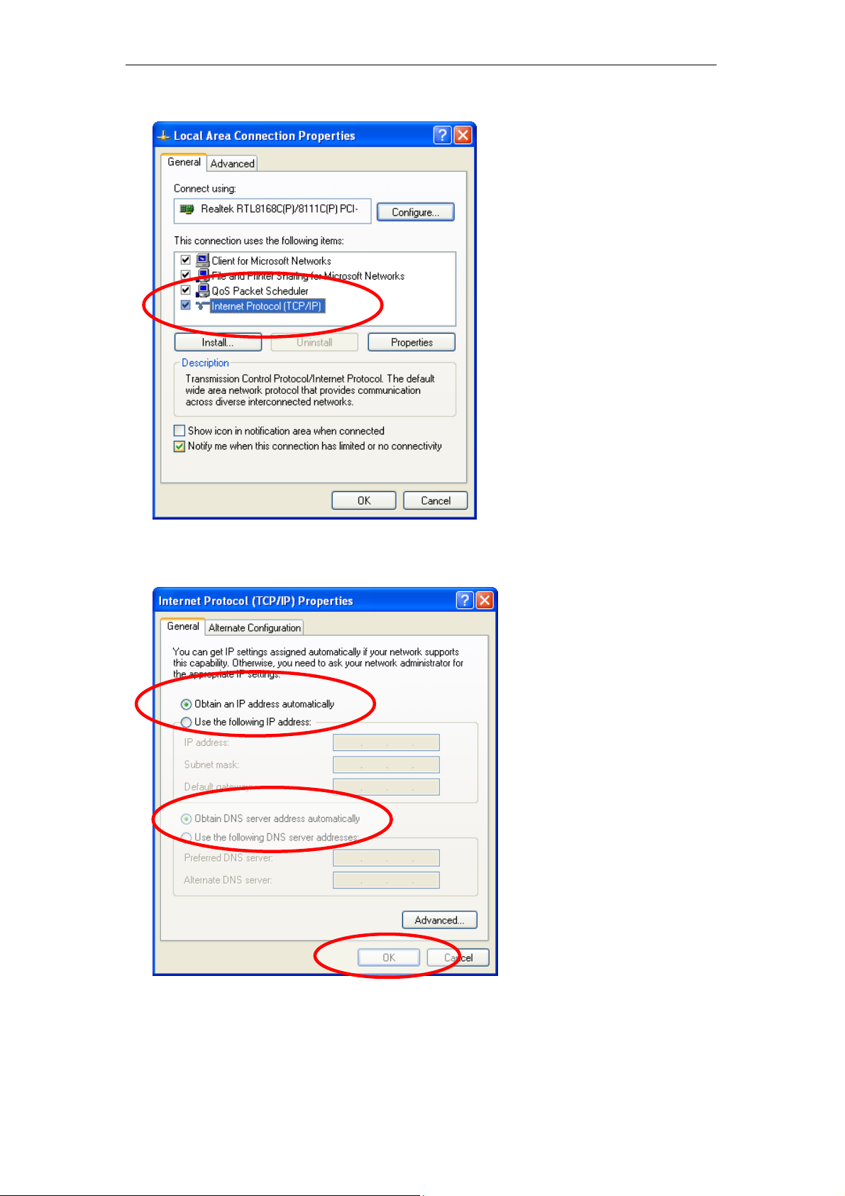
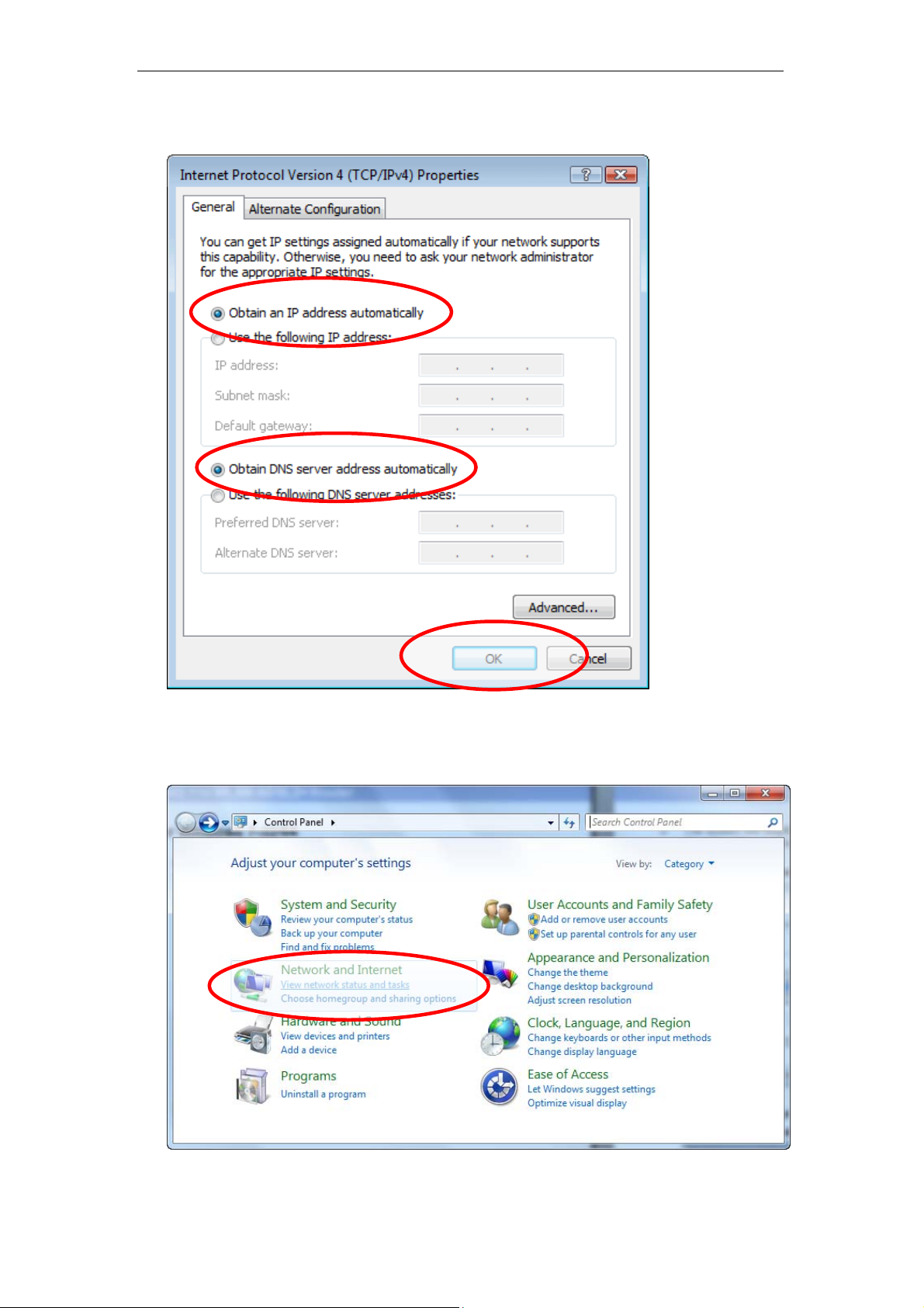
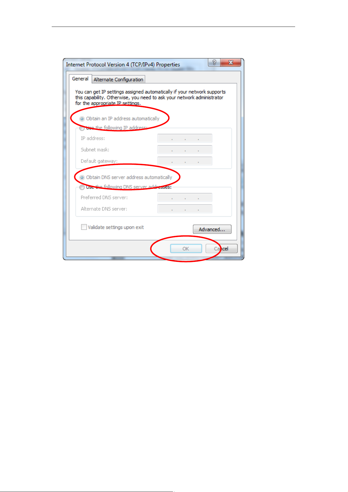
3. Double click on "Internet Protocol (TCP/ IP)".
4. Check "Obtain an IP address automatically" and “Obtain DNS server
address automatically” then click on "OK" to continue.
5. Click "Show icon in notification area when connected" (see screen
image in 3. above) then Click on "OK" to complete the setup procedures.
18
Page 19
Wireless 802.11 b/g/n ADSL2+ Router User’s Guide
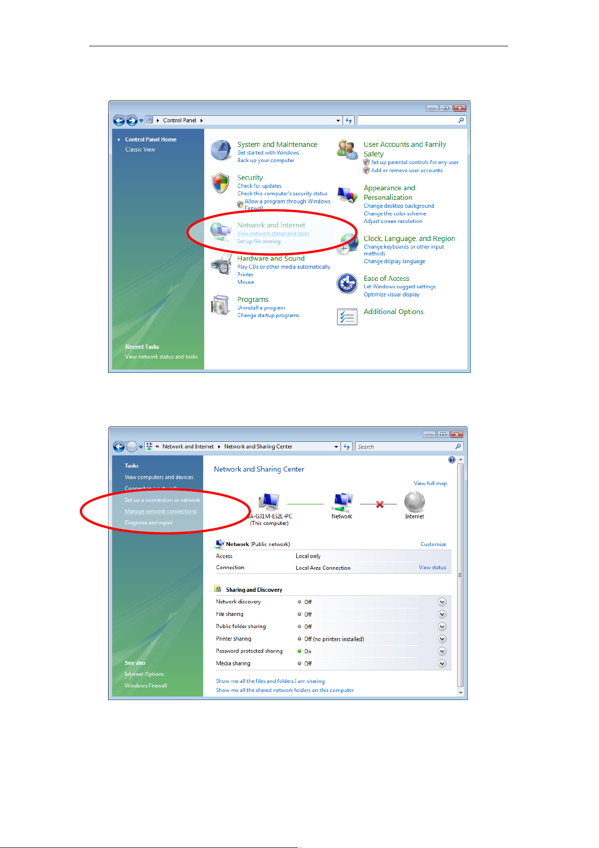
For Windows Vista-32/64
1. Click on “Start” -> “Control Panel” -> “View network status and tasks”.
2. In the Manage network connections, click on “Manage network
connections” to continue.
19
Page 20
Wireless 802.11 b/g/n ADSL2+ Router User’s Guide
3. Single RIGHT click on “Local Area connection", then click "Properties".
4. The screen will display the information “User Account Control” and click
“Continue” to continue.
5. Double click on "Internet Protocol Version 4 (TCP/IPv4)".
20
Page 21
Wireless 802.11 b/g/n ADSL2+ Router User’s Guide
6. Check "Obtain an IP address automatically" and “Obtain DNS server
address automatically” then click on "OK" to continue.
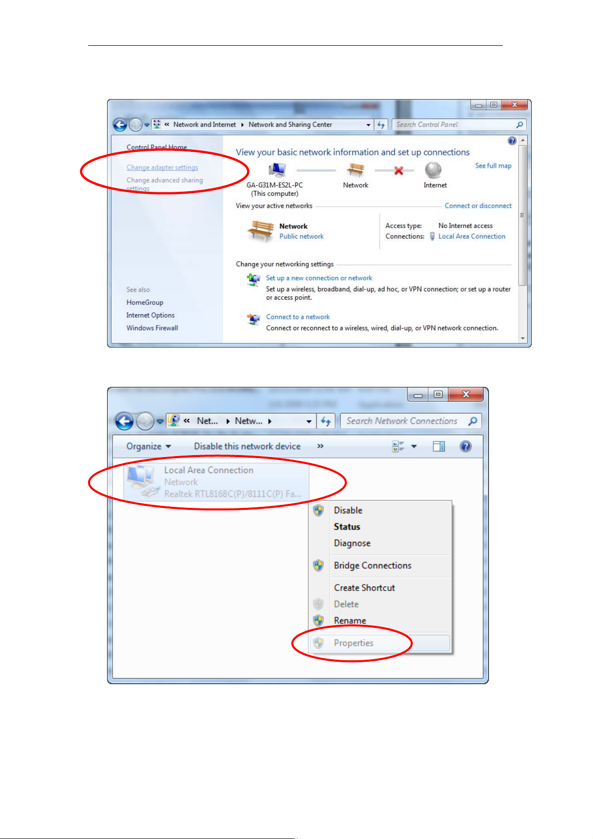
For Windows 7-32/64
1. Click on “Start” -> “Control Panel” (in Category View) -> “View netw ork
status and tasks”.
21
Page 22
Wireless 802.11 b/g/n ADSL2+ Router User’s Guide
2. In the Control Panel Home, click on “Change adapter settings” to
continue.
3. Single RIGHT click on “Local Area connection", then click "Properties".
22
Page 23
Wireless 802.11 b/g/n ADSL2+ Router User’s Guide
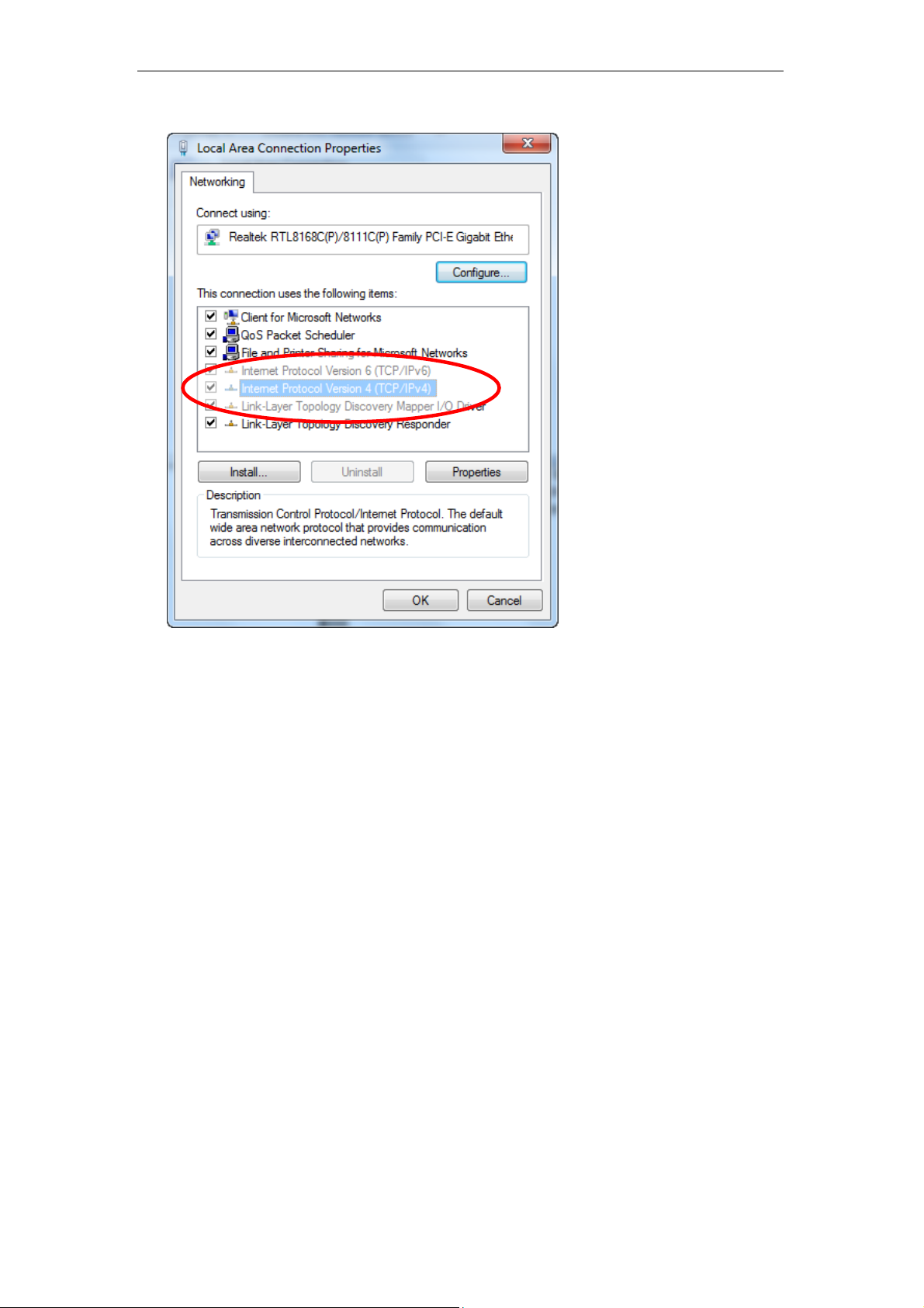
4. Double click on "Internet Protocol Version 4 (TCP/IPv4)".
23
Page 24
Wireless 802.11 b/g/n ADSL2+ Router User’s Guide
5. Check "Obtain an IP address automatically" and “Obtain DNS server
address automatically” then click on "OK" to continue.
24
Page 25
Wireless 802.11 b/g/n ADSL2+ Router User’s Guide
4 Utility CD execution
Connecting the Hardware
This section describes how to connect the device to the wall
phone port, the power outlet and your computer(s) or network.
1. Before you begin to execute utility CD Installations, please
ensure the 802.11n WLAN ADSL2+ Router has been
powered on.
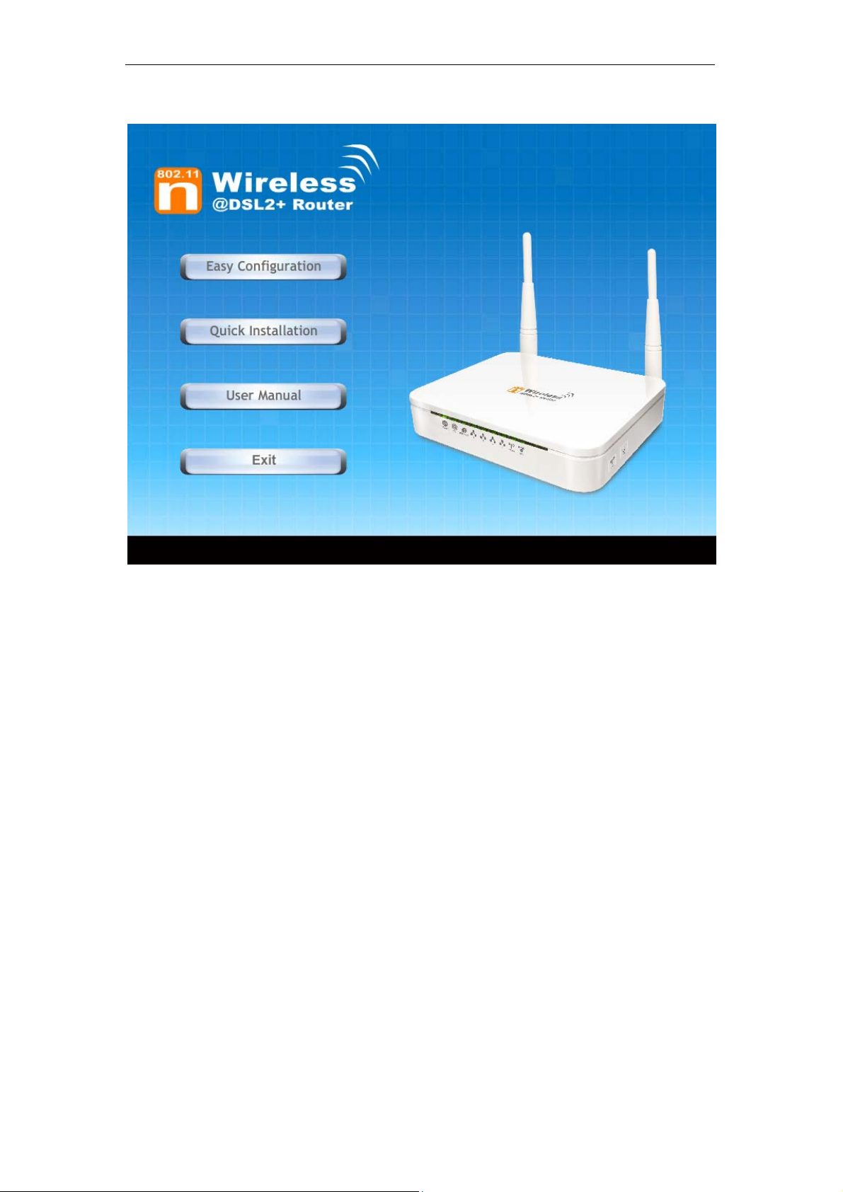
2. Please insert the supplied CD into your CD-ROM drive.
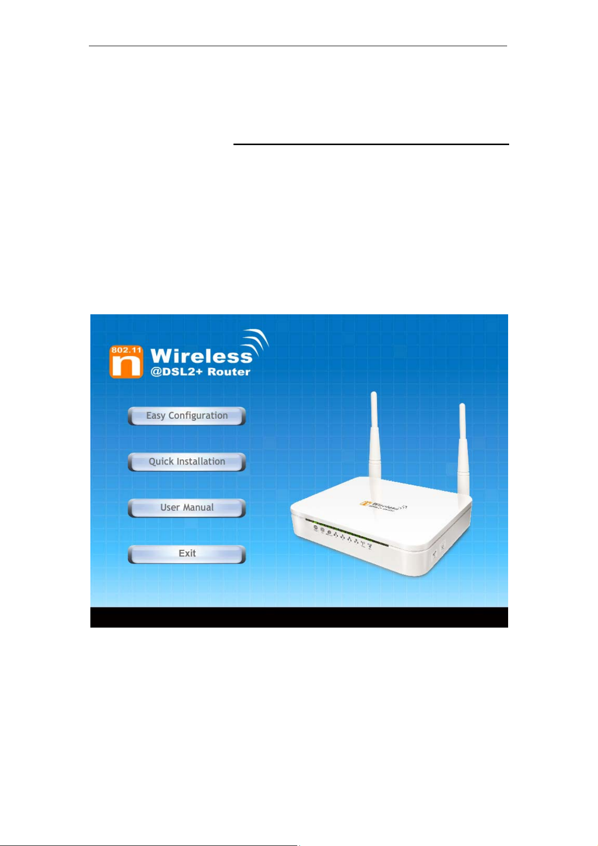
3. The CD should auto-start, displaying the window shown in 4.
below. If your CD does not start automatically, go to
Windows Explorer, Select your CD drive and double click
"Autorun.exe".
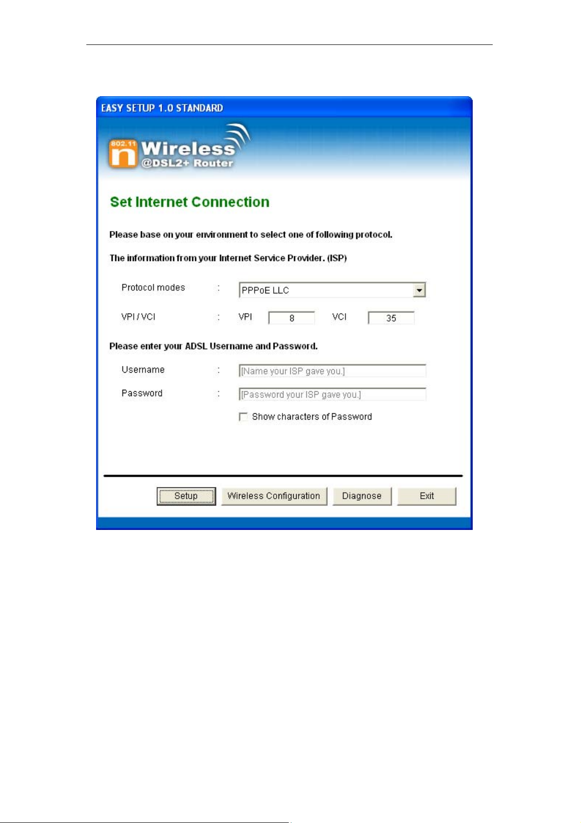
4. To configure the Internet and Wireless configuration, please
click the " Easy Configuration ".
25
Page 26
Wireless 802.11 b/g/n ADSL2+ Router User’s Guide
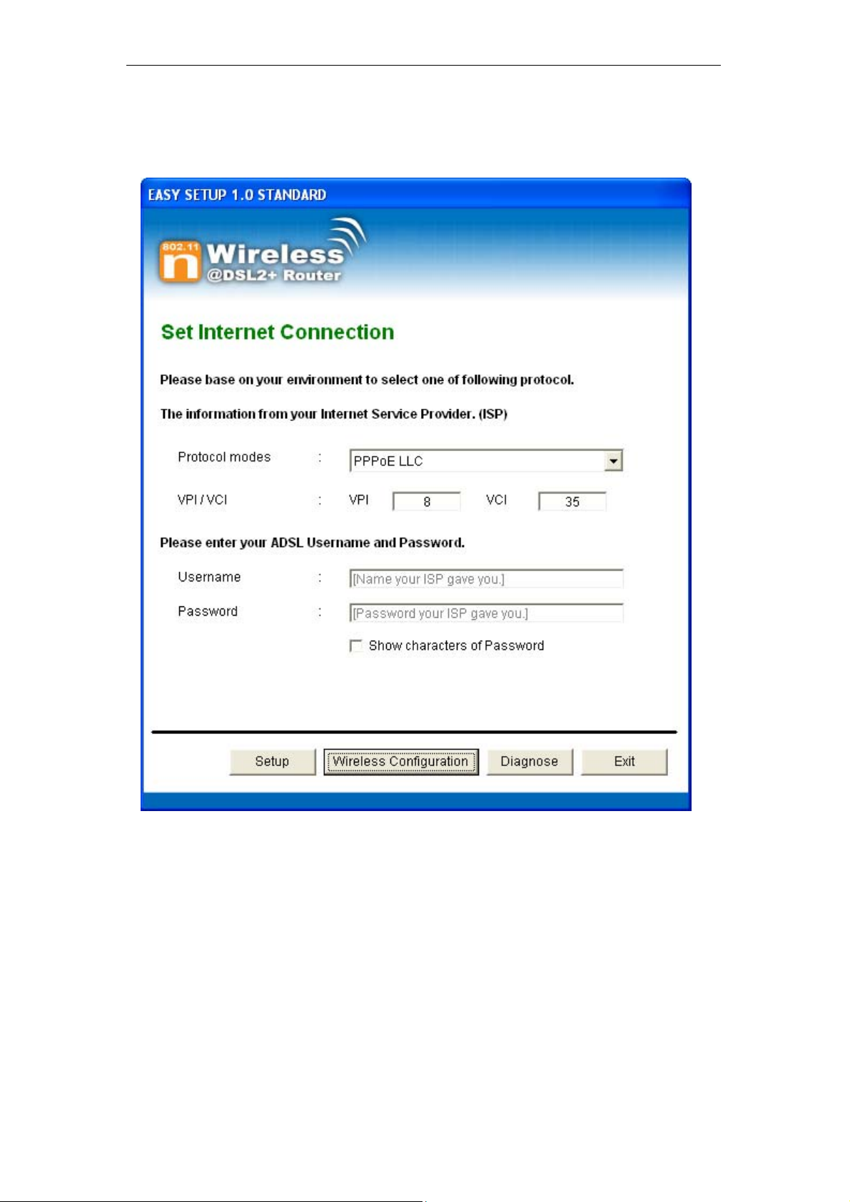
5. Select Protocol mode and enter the VPI, VCI, Username
and Password your ISP (Internet Services Provider)
provided.
6. Please click “ Wireless Configuration ” button.
26
Page 27
Wireless 802.11 b/g/n ADSL2+ Router User’s Guide
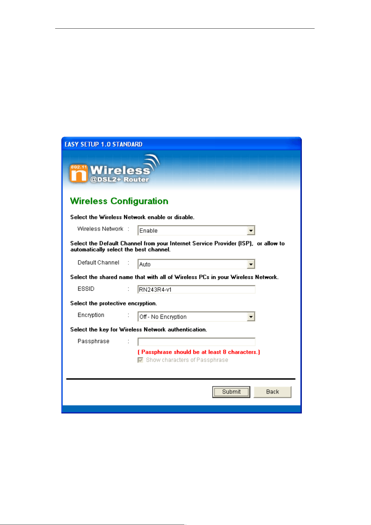
7. Please configure the Wireless Network, Default Chann
el,
ESSID if you want to change. (Recommended to use
default settings, Wireless Net work = Enable, Default
Channel = Auto, ESSID = RN243R4-v1).
8. Choose the Encryption type if necessary, as Off – No
Encryption / 64 Bit En
cryption / 128 Bit Encryption / Wi-Fi
Protected Access2 (AES-CCMP) and WPA Mixed Mode.
(Recommended to use defa
ult settings, Encryption
type = Off – No Encryption). For example, you choose
Off – No Encryption.
9. Configure related Wireless Configurations and then click
"Submit" button to continue.
27
Page 28
Wireless 802.11 b/g/n ADSL2+ Router User’s Guide
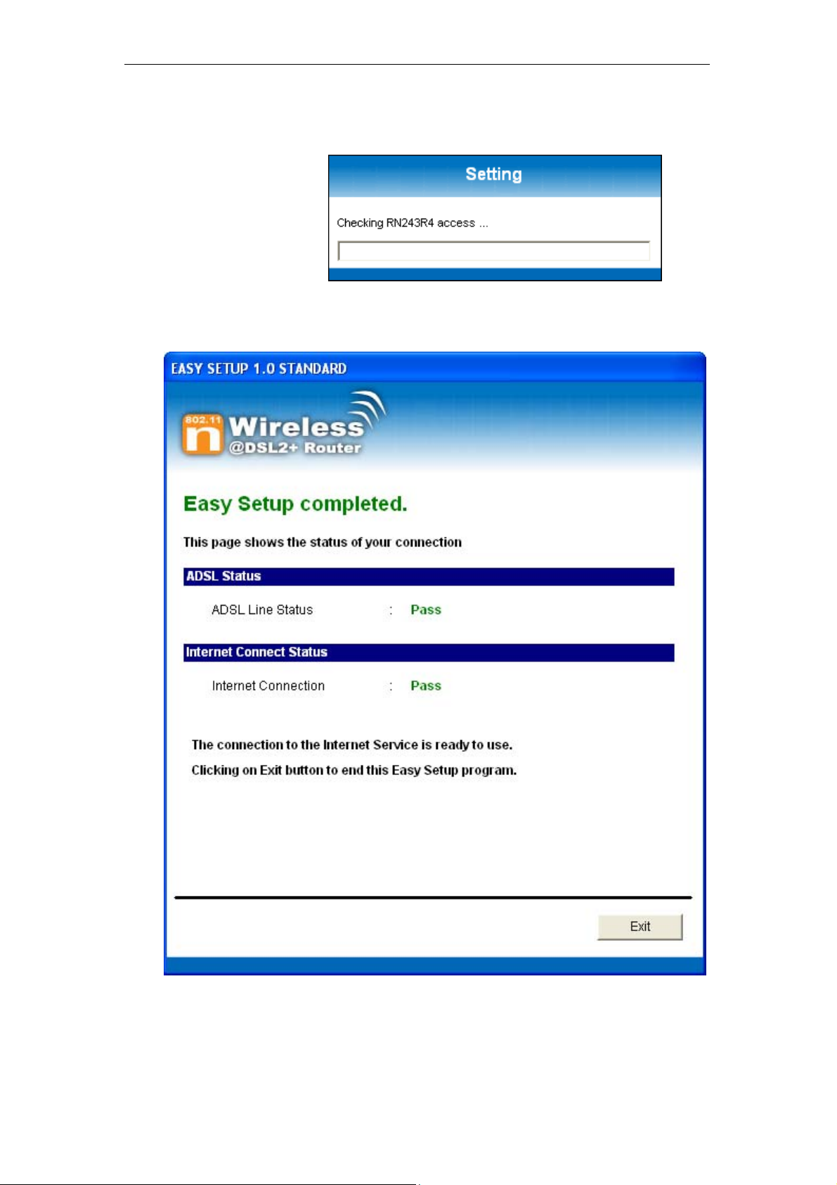
10. Please click “ Setup ” button, when the procedure is
completed, it will start to configure the device for a while.
28
Page 29
Wireless 802.11 b/g/n ADSL2+ Router User’s Guide
11. Now, checking 802.11n WLAN ADSL 2+ Router hardware
connection, ADSL2+ settings, WLAN settings, and ADSL2+
Line connection status.
12. Easy setup configuration completed. Click on " Exit " to exit
this program.
29
Page 30
Wireless 802.11 b/g/n ADSL2+ Router User’s Guide
13. Click on " Exit " to exit this program.
14. Now, the 802.11n WLAN ADSL2+ Router has been
configured completely, and suitable for Wireless and
Internet Connections.
30
Page 31

Wireless 802.11 b/g/n ADSL2+ Router User’s Guide
Wireless Connection
For easy installation it is saved to keep the settings. You can
later change the wireless settings via the wireless configuration
menu. (see user manual on the CD – Chapter 13 and other).
1. Double click on the wireless icon on your computer and
search for the wireless network that you enter ESSID name.
2. Click on the wireless network that you enter ESSID name
(the default setting ESSID = RN243R4-v1) to connect.
31
Page 32

Wireless 802.11 b/g/n ADSL2+ Router User’s Guide
3. If the wireless network isn’t encrypted, click on "Connect
Anyway" to connect.
4. If the wireless network is encrypted, enter the network key
that belongs to your authentication type and key. (the
default settings Security Mode = Disable). You can later
change this network key via the wireless configuration
menu. (see user manual on the CD – Chapter 13 and other).
5. Click on "Connect" or "Apply".
6. Now you are ready to use the Wireless Network to Internet
or intranet.
32
Page 33

Wireless 802.11 b/g/n ADSL2+ Router User’s Guide
5 Getting Started with the Web pages
The Wireless ADSL2+ Router includes a series of Web pages
that provide an interface to the software installed on the device.
It enables you to configure the device settings to meet the
needs of your network. You can access it through your web
browser from any PC connected to the device via
Accessing the Web pages
To access the Web pages, you need the following:
• A PC or laptop connected to the LAN port on the device.
• A web browser installed on the PC. The minimum browser
version requirement is Internet Explorer v4 or Netscape v4.
For the best display quality, use latest version of Internet
Explorer, Netscape or Mozilla Firefox.From any of the LAN
computers, launch your web browser, type the following
URL in the web address (or location) box, and press [Enter]
on your keyboard:
http://192.168.1.1
the LAN ports.
The Status homepage for the web pages is displayed:
33
Page 34

Wireless 802.11 b/g/n ADSL2+ Router User’s Guide
Figure 1: Homepage
34
Page 35

Wireless 802.11 b/g/n ADSL2+ Router User’s Guide
The first time that y ou click o n an en try from the l efthand menu, a login box is display ed. You must enter
your username and password to access the pages.
A login screen is displayed:
Note
Figure 2: Login screen
1. Enter your user name and password. The first time you log
into the program, use these defaults:
User Name:
Password:
You can change the password at any time or you can configure your
device so that you do not need to enter a password. See Password.
2. Click on OK. You are now ready to configure your device.
This is the first page displayed each time you log in to the Web
pages. This page contains links to the following pages:
• Addressing; links to the Addressing page that controls your
device’s network address. See Addressing.
• Internet Access; links to the Internet Access page that
controls how your device connects to the Internet. See
Internet Access.
admin
admin
Note
If you receive an error message or the Welcome page is not
displayed, see Troubleshooting Suggestions.
35
Page 36

Wireless 802.11 b/g/n ADSL2+ Router User’s Guide
Testing your Setup
Once you have connected your hardware and configured your
PCs, any computer on your LAN should be able to use the
device’s DSL connection to access the Internet.
To test the connection, turn on the device, wait for 30 seconds
and then verify that the LEDs are illuminated as follows:
Table 1. LED Indicators
LED Behavior
POWER
ETH
Link
INTERNET
Solid green to indicate that the device is turned on. If this
light is not on, check the power cable attachment.
Flashing on/off while the device is booting. After about 1015 seconds, solid green to indicate that the device can
communicate with your LAN.
Flashing on/off while data is being transmitted. Solid green
to indicate that the device has successfully established a
connection with your ISP.
Flashing on/off while data is being transferred. Solid green
when a valid IP address has been assigned to the device
by the ISP.
If the LEDs illuminate as expected, test your Internet connection
from a LAN computer. To do this, open your web browser, and
type the URL of any external website (such as
http://www.yahoo.com
). The LED labeled INTERNET should
blink rapidly and then appear solid as the device connects to the
site.
If the LEDs do not illuminate as expected, you may need to
configure your Internet access settings using the information
provided by your ISP. For details, see Internet Access. If the
LEDs still do not illuminate as expected or the web page is not
displayed, see Troubleshooting Suggestions or contact your
ISP for assistance.
Default device settings
In addition to handling the DSL connection to your ISP, the DSL
Modem can provide a variety of services to your network. The
device is preconfigured with default settings for use with a
typical home or small office network.
The table below lists some of the most important default settings;
these and other features are described fully in the subsequent
chapters. If you are familiar with network configuration, review
these settings to verify that they meet the needs of your network.
Follow the instructions to change them if necessary. If you are
unfamiliar with these settings, try using the device without
modification, or contact your ISP for assistance.
We strongly recommend that you conta ct your ISP prior to
changing the default configuration.
WARNING
36
Page 37

Wireless 802.11 b/g/n ADSL2+ Router User’s Guide
Option Default Setting Explanation/Instructions
LINE Port IP
Address
Unnumbered interface:
192.168.1.1
Subnet mask:
This is the temporary public IP address of the WAN
port on the device. It is an unnumbered interface that
is replaced as soon as your ISP assigns a ‘real’ IP
address. See Internet Access.
255.255.255.255
LAN Port
IP Address
Assigned static IP address:
192.168.1.1
Subnet mask:
This is the IP address of the LAN port on the device.
The LAN port connects the device to your Ethernet
network. Typically, you will not need to change this
address. See LAN.
255.255.255.0
DHCP (Dynamic
Host Configuration
Protocol)
DHCP server enabled with the
following pool of addresses:
192.168.1.2
through
192.168.1.254
The Wireless ADSL2+ Router maintains a pool of
private IP addresses for dynamic assignment to your
LAN computers. To use this service, you must have
set up your computers to accept IP information
dynamically, as described in Services -> DHCP
Settings.
NAT (Network
Address Translation)
NAT enabled
Your computers’ private IP addresses (see DHCP
above) will be translated to your public IP address
whenever the PCs access the Internet. See Services
-> Firewall.
37
Page 38

Page 39

Wireless 802.11 b/g/n ADSL2+ Router User’s Guide
6 Overview
The Overview page displays useful information about the setup
of your device, including:
• details of the device’s Internet access settings
• version information about your device
To display this page:
From the head menu, click on Status. The following page is
displayed:
39
Page 40

Wireless 802.11 b/g/n ADSL2+ Router User’s Guide
Figure 3: Overview page
The information displayed on this page is explained in detail in
the following sections.
40
Page 41

Wireless 802.11 b/g/n ADSL2+ Router User’s Guide
Internet access settings
This section displays details of the settings that allow your
device to access the Internet. These details include:
IP address and
subnet mask:
Default gateway: The address of the ISP server through
DNS servers: The Domain Name System (DNS)
Your ISP assigns all of these settings. In most cases, you will
not need to make changes to these settings in order for your
Internet connection to work. If your ISP does ask you to change
any of these settings, follow the instructions for manually
configuring your device in Internet Access.
The IP address and subnet mask
assigned to your WAN interface. This
address is used temporarily until your
ISP assigns a real IP address (via DHCP
or PPP – see Internet Access.
which your Internet connection will be
routed.
servers used by your ISP to map domain
names to IP addresses.
About Wireless ADSL2+ Router
This section displays details of your device’s hardware and
firmware versions. If you need to contact your ISP’s support
team, they may need to know which hardware/firmware
versions you are using in order to answer your query.
Your hardware version details contain information about the
make and model of your device and its exact hardware
components.
Your firmware version details contain information about the
software program running on your device. They then make the
latest updated version available to you via the Internet. For
details of how to update your firmware, see Admin -> Upgrade
Firmware.
41
Page 42

Wireless 802.11 b/g/n ADSL2+ Router User’s Guide
7 Status
You can view statistics on the processing of IP packets on the
networking interfaces. You will not typically need to view this
data, but you may find it helpful when working with your ISP to
diagnose network and Internet data transmission problems.
Device Info
This page shows the current status and some basic settings of
the device.
1. From the head Status menu, The following page is
displayed:
2. To display updated statistics showing any new data since
you opened this page, click Refresh.
42
Page 43

Wireless 802.11 b/g/n ADSL2+ Router User’s Guide
43
Page 44

Wireless 802.11 b/g/n ADSL2+ Router User’s Guide
ADSL
This page shows the ADSL line statistic information.
1. From the head Status menu, click on ADSL The following
page is displayed:
2. To display updated statistics showing any new data since
you opened this page, click Refresh.
44
Page 45

Wireless 802.11 b/g/n ADSL2+ Router User’s Guide
Statistics
This page shows the packet statistics for transmission and
reception regarding to network interface.
1. From the head Status menu, click on Statistics The
following page is displayed:
2. To display updated statistics showing any new data since
you opened this page, click Refresh.
45
Page 46

Wireless 802.11 b/g/n ADSL2+ Router User’s Guide
8 Internet Access
This chapter describes how to configure the way that your
device connects to the Internet. Your ISP determines what type
of Internet access you should use and provides you with any
information that you need in order to configure the Internet
access to your device.
Your device needs the following address information in order to
access the Internet:
ATM PVC To configure ATM PVC, enter the VPI
and VCI provided by ISP. Select the
Service Type Index, Service Category
and enter the following information:
• Peak Cell Rate
• Sustainable Cell Rate
• Maximum Burst Size
Connection Type To configure the connection type, select
the protocol and encapsulation type as
indicated by ISP. Supported Protocol
types are:
• RFC1483 Bridged
• RFC1483 MER
• PPPoE
• PPPoA
• RFC1483 Routed
Supported Encapsulation types are:
• VCMUX
• LLC/SNAP
WAN IP Settings To configure WAN IP settings, enter the
information as indicated by ISP.
Enable/Disable the Access Concentrator
option. Either enter the WAN IP or select
the option to automatically obtain IP
address.
Check as applicable the following two
options:
• Enable NAT
• Add default Route
Broadband
Username and
Password
46
To configure Broadband Username and
Password, enter the user name and
password details. Also set the session
establishment condition as one of the
following:
• Continuous
Page 47

Wireless 802.11 b/g/n ADSL2+ Router User’s Guide
• Connect on demand. Enter the
minutes after which the session
must be disconnected, if no
activity takes place.
• Manual. Enter the minutes after
which the session must be
disconnected, if no activity takes
place.
In most cases, you will not need to configure your device with
these addresses because your ISP is likely to use an Internet
access type which automatically assigns addresses to your
device. For more information, see Types of Internet Access.
Types of Internet Access
The types of Internet access available are as follows:
• PPP Internet access – your device uses a Point to Point
Protocol (PPP) to carry data between your ISP and your
computer. To use PPP Internet access, you must enter a
PPP login username and password the first time to log
on. The IP addresses required to access your ISP’s
Internet service are automatically configured.
Your device supports PPPoE (over Ethernet).
• PPP Internet access – your device uses a Point to Point
Protocol (PPP) to carry data between your ISP and your
computer. To use PPP Internet access, you must enter a
PPP login username and password the first time to log
on. The IP addresses required to access your ISP’s
Internet service are automatically configured.
Your device supports PPPoA (over ATM).
• Bridged Internet access – your device uses a Bridge mode
with your PPPoE Client Software to carry data between
your ISP and your computer. To use Bridged Internet
access with your PPPoE Client Software, you must enter
a PPP login username and password the first time to log
on. The IP addresses required to access your ISP’s
Internet service are automatically configured.
Your device supports RFC 1483 Bridged Mode).
47
Page 48

Wireless 802.11 b/g/n ADSL2+ Router User’s Guide
Configuring your PPPoE DSL connection
If your ISP’s Internet service uses PPPoE you need to set up a
PPP login account. The first time that you login to the Internet,
your ISP will ask you to enter a username and password so
they can check that you are a legitimate, registered Internet
service user. Your device stores these authentication details, so
you will not have to enter this username and password every
time you login.
Your ISP may also tell you to set unique path and circuit
numbers (called VPI and VCI) in order to connect your device to
the ISP’s Internet service. In most cases, your device will use
default settings, so you may not need to enter these values.
Note
Your ISP will provide you with the login details and VPI/VCI
values necessary to set up a PPP login account.
If your ISP wants you to connect to the Internet using PPP,
follow the instructions below.
48
Page 49

Wireless 802.11 b/g/n ADSL2+ Router User’s Guide
1. From the head Setup menu, click on WAN. The following
page is displayed:
2. Enter VCI and VPI setting determined by your ISP.
3. Select the Encapsulation determined by your ISP.
4. From the Channel Mode drop-down list, select PPPoE
setting.
5. From the IP Protocol drop-down list, select the IP Protocol,
IPv4, IPv6 or dual stacks IPv4/IPv6 determined by your ISP.
6. Enter User Name/Password provided by your ISP. Type
them in the relevant boxes.
7. IPv6 WAN setting determined by your ISP.
8. If you are happy with your settings, click Add
9. Your configuration is complete.
10. Now you are ready to Surf the Internet !!!
49
Page 50

Wireless 802.11 b/g/n ADSL2+ Router User’s Guide
Configuring your PPPoA DSL connection
If your ISP’s Internet service uses PPPoA you need to set up a
PPP login account. The first time that you login to the Internet,
your ISP will ask you to enter a username and password so
they can check that you are a legitimate, registered Internet
service user. Your device stores these authentication details, so
you will not have to enter this username and password every
time you login.
Your ISP may also tell you to set unique path and circuit
numbers (called VPI and VCI) in order to connect your device to
the ISP’s Internet service. In most cases, your device will use
default settings, so you may not need to enter these values.
Note
Your ISP will provide you with the login details and VPI/VCI
values necessary to set up a PPP login account.
If your ISP wants you to connect to the Internet using PPP,
follow the instructions below.
50
Page 51

Wireless 802.11 b/g/n ADSL2+ Router User’s Guide
1. From the head Setup menu, click on WAN. The following
page is displayed:
2. Enter VCI and VPI setting determined by your ISP.
3. Select the Encapsulation determined by your ISP.
4. From the Channel Mode drop-down list, select PPPoA
setting.
5. From the IP Protocol drop-down list, select the IP Protocol,
IPv4, IPv6 or dual stacks IPv4/IPv6 determined by your ISP.
6. Enter User Name/Password provided by your ISP. Type
them in the relevant boxes.
7. IPv6 WAN setting determined by your ISP.
8. If you are happy with your settings, click Add
9. Your configuration is complete.
10. Now you are ready to Surf the Internet !!!
51
Page 52

Wireless 802.11 b/g/n ADSL2+ Router User’s Guide
Configuring your Bridged DSL connection
1. From the head Setup menu, click on WAN. The following
page is displayed:
2. Enter VCI and VPI setting determined by your ISP.
3. Select the Encapsulation determined by your ISP.
4. From the Channel Mode drop-down list, select 1483
Bridged setting.
5. If you are happy with your settings, click Add
6. Now you can load your PPPoE Client Software onto your
PC.
7. Now you can load your PPPoE Client Software with user
name and password which determined by your ISP onto
your PC.
52
Page 53

Wireless 802.11 b/g/n ADSL2+ Router User’s Guide
Configuring your 1483 MER by DHCP
1. From the head Setup menu, click on WAN. The following
page is displayed:
2. Enter VCI and VPI setting determined by your ISP.
3. Select the Encapsulation determined by your ISP.
4. From the IP Protocol drop-down list, select the IP Protocol,
IPv4, IPv6 or dual stacks IPv4/IPv6 determined by your ISP.
5. From the Channel Mode drop-down list, select 1483 MER
setting.
6. From the Type ratio, click DHCP.
7. IPv6 WAN setting determined by your ISP.
8. If you are happy with your settings, click Add
9. Your configuration is complete.
10. Now you are ready to Surf the Internet !!!
53
Page 54

Wireless 802.11 b/g/n ADSL2+ Router User’s Guide
Configuring your 1483 MER by Fixed IP
1. From the head Setup menu, click on WAN. The following
page is displayed:
2. Enter VCI and VPI setting determined by your ISP.
3. Select the Encapsulation determined by your ISP.
4. From the Channel Mode drop-down list, select 1483 MER
setting.
5. From the IP Protocol drop-down list, select the IP Protocol,
IPv4, IPv6 or dual stacks IPv4/IPv6 determined by your ISP.
6. From the Type ratio, click Fixed IP.
7. Enter Local IP Address, Subnet Mask and Remote IP
Address which was given by Telecom or by your Internet
Service Provider (ISP).
8. IPv6 WAN setting determined by your ISP.
9. If you are happy with your settings, click Add
54
Page 55

Wireless 802.11 b/g/n ADSL2+ Router User’s Guide
10. From the head Service menu, click on DNS.
11. Check on Set DNS Manually ratio.
12. Enter DNS setting determined by your ISP.
13. Click Apply Changes button.
14. Your configuration is complete.
15. Now you are ready to Surf the Internet !!!
ATM Settings
The page is for ATM PVC QoS parameters setting. The DSL
device support 4 QoS mode —CBR/rt-VBR/nrt-VBR/UBR.
1. From the left-hand WAN menu, click on ATM. The following
page is displayed:
55
Page 56

Wireless 802.11 b/g/n ADSL2+ Router User’s Guide
Field Description
VPI
Virtual Path Identifier. This is read-only field and is
selected on the Select column in the Current ATM VC
Table.
VCI
QoS
PCR
Virtual Channel Identifier. This is read-only field and is
selected on the Select column in the Current ATM VC
Table. The VCI, together with VPI, is used to identify
the next destination of a cell as it passes through to the
ATM switch.
Quality of Server, a characteristic of data transmission
that measures how accurately and how quickly a
message or data is transferred from a source host to a
destination host over a network. The four QoS options
are:
−UBR (Unspecified Bit Rate): When UBR is selected,
the SCR and MBS fields are disabled.
−CBR (Constant Bit Rate): When CBR is selected, the
SCR and MBS fields are disabled.
−nrt-VBR (non-real-time Variable Bit Rate): When nrtVBR is selected, the SCR and MBS fields are enabled.
−rt-VBR (real-time Variable Bit Rate): When rt-VBR is
selected, the SCR and MBS fields are enabled.
Peak Cell Rate, measured in cells/sec., is the cell rate
which the source may never exceed.
SCR
Sustained Cell Rate, measured in cells/sec., is the
average cell rate over the duration of the connection.
MBS
Maximum Burst Size, a traffic parameter that specifies
the maximum number of cells that can be transmitted
at the peak cell rate.
Function Button Description
Apply Changes
Undo Discard your settings.
Set new PVC OoS mode for the selected PVC. New
parameters will take effect after save into flash
memory and reboot the system. See section “Admin”
for save details.
56
Page 57

Wireless 802.11 b/g/n ADSL2+ Router User’s Guide
ADSL Settings
The ADSL setting page allows you to select any combination of
DSL training modes.
1. From the left-hand WAN menu, click on ADSL Settings.
The following page is displayed:
57
Page 58

Wireless 802.11 b/g/n ADSL2+ Router User’s Guide
Field Description
ADSL modulation Choose prefered xdsl standard protocols.
AnnexL Option Enable/Disable ADSL2/ADSL2+ Annex L capability.
AnnexM Option Enable/Disable ADSL2/ADSL2+ Annex M capability.
ADSL Capability “Bitswap Enable” : Enable/Disable bitswap capability.
G.lite : G.992.2 Annex A
G.dmt : G.992.1 Annex A
T1.413 : T1.413 issue #2
ADSL2 : G.992.3 Annex A
ADSL2+ : G.992.5 Annex A
“SRA Enable” : Enable/Disable SRA (seamless rate
adaptation) capability.
Function Button Description
Tone Mask
Apply Changes
Choose tones to be masked. Mased tones will not
carry any data.
Click to save the setting to the configuration and the
modem will be retrained.
58
Page 59

User’s Guide Configuring your Computers
9 Local Network Configuration
The Addressing page displays information about your LAN IP
address and allows you to change the address and subnet
mask assigned to your device.
You should only change the addressing details if your ISP asks
Note
you to, or if you are familiar with network configuration. In mo st
cases, you will not need to make any changes to this
configuration.
Changing the LAN IP address and subnet mask
1. From the head Setup menu, click on LAN. The following
page is displayed:
59
Page 60

User’s Guide Configuring your Computers
60
Page 61

User’s Guide Configuring your Computers
2. From the left-hand LAN menu, click on DHCP Settings.
61
Page 62

User’s Guide Configuring your Computers
3. Change the IP Pool Range and then click Apply Changes
button.
4. Change setting successfully! Click OK button.
62
Page 63

User’s Guide Configuring your Computers
5. From the left-hand LAN menu, click on LAN.
6. Type a new IP Address and Subnet Mask.
7. Click Apply Changes.
8. Please click 10.0.0.2 to continue configuration.
9. The primary IP address is being changed to 10.0.0.2
netmask 255.255.255.0. Then please go to http://10.0.0.2 to
continue. Your browser communicates with the web server
via the LAN connection, and changing the IP address may
disrupt this.
You may also need to renew your DHCP lease:
Windows 95/98
a. Select Run... from the Start menu.
b. Enter winipcfg and click OK.
c. Select your ethernet adaptor from the pull-down menu
d. Click Release All and then Renew All.
e. Exit the winipcfg dialog.
Windows NT/Windows 2000/Windows XP
a. Bring up a command window.
b. Type ipconfig /release in the command window.
c. Type ipconfig /renew.
d. Type exit to close the command window.
Linux
63
Page 64

User’s Guide Configuring your Computers
a. Bring up a shell.
b. Type pump -r to release the lease.
c. Type pump to renew the lease.
Note
If you change the LAN IP address of the device while conne cted
through your Web browser, you will be disconnected. You must
open a new connection by entering your new LAN IP address as
the URL.
10. From the left-hand menu, click on Save.
Adding the Secondary LAN IP address and subnet mask
1. From the left-hand LAN menu, click on LAN.
2. Check on Secondary IP.
3. Type the Secondary IP Address and Subnet Mask.
4. Click Apply Changes.
5. From the left-hand menu, click on Save.
64
Page 65

User’s Guide Configuring your Computers
10 DHCP Settings
You can configure your network and DSL device to use the
Dynamic Host Configuration Protocol (DHCP). This page
provides DHCP instructions for implementing it on your network
by selecting the role of DHCP protocol that this device wants to
play. There are two different DHCP roles that this device can act
as: DHCP Serve and DHCP Relay. When acting as DHCP
server, you can setup the server parameters at the DHCP
Server page; while acting as DHCP Relay, you can setup the
relay at the DHCP Relay page.
DHCP Server Configuration
1. From the left-hand LAN menu, click on DHCP Settings.
2. From Services check ratio, click on DHCP Server Mode.
3. Type a new IP Pool Range, Subnet Mask, Max Lease Time,
Domain Name and Gateway Address.
4. Click on Apply Changes.
65
Page 66

User’s Guide Configuring your Computers
Field Description
IP Pool Range Specify the lowest and highest addresses in the pool.
Max Lease Time
The Lease Time is the amount of time that a network
user is allowed to maintain a network connection to the
device using the current dynamic IP address. At the
end of the Lease Time, the lease is either renewed or
a new IP is issued by the DHCP server. The amount of
time is in units of seconds. The default value is 86400
seconds (1 day). The value –1 stands for the infinite
lease.
Domain Name
A user-friendly name that refers to the group of hosts
(subnet) that will be assigned addresses from this pool.
Function Button Description
Show Client
Apply Changes
This shows the assigned IP address, MAC address
and time expired for each DHCP leased client.
Set new DHCP server configuration. New parameters
will take effect after save into flash memory and reboot
the system. See section “Admin” for save details.
Undo Discard your changes.
5. From the left-hand menu, click on Save.
66
Page 67

User’s Guide Configuring your Computers
DHCP Relay Configuration
1. From the left-hand LAN menu, click on DHCP Settings.
2. From Services check ratio, click on DHCP Relay Mode.
3. Type DHCP server IP Addresses for DHCP Relay.
4. Click on Apply Changes.
Field Description
DHCP Server
Address
Function Button Description
Apply Changes
5. From the left-hand menu, click on Save.
Specify the IP address of your ISP’s DHCP server.
Requests for IP information from your LAN will be
passed to the default gateway, which should route the
request appropriately.
Set new DHCP server configuration. New parameters
will take effect after save into flash memory and reboot
the system. See section “Admin” for save details.
67
Page 68

User’s Guide Configuring your Computers
6. You need to renew your DHCP lease:
Windows 95/98
a. Select Run... from the Start menu.
b. Enter winipcfg and click OK.
c. Select your ethernet adaptor from the pull-down menu
d. Click Release All and then Renew All.
e. Exit the winipcfg dialog.
Windows NT/Windows 2000/Windows XP
a. Bring up a command window.
b. Type ipconfig /release in the command window.
c. Type ipconfig /renew.
d. Type exit to close the command window.
Linux
a. Bring up a shell.
b. Type pump -r to release the lease.
c. Type pump to renew the lease.
68
Page 69

User’s Guide Configuring your Computers
DHCP None Configuration
1. From the left-hand Services menu, click on DHCP Settings.
2. From Services check ratio, click on None Mode.
3. Click on Apply Changes.
Function Button Description
Apply Changes
Set new DHCP server configuration. New parameters
will take effect after save into flash memory and reboot
the system. See section “Admin” for save details.
4. From the left-hand menu, click on Save.
69
Page 70

User’s Guide Configuring your Computers
11 DHCP Static Configuration
This page lists the fixed IP/MAC address on your LAN. The
device distributes the number configured to hosts on your
network as they request Internet access.
DHCP Static Configuration
1. From the left-hand LAN menu, click on DHCP Static.
2. Enter the desired IP Address to specific MAC Address.
3. Click on Add.
4. From the left-hand menu, click on Save.
70
Page 71

User’s Guide Configuring your Computers
12 LAN IPv6 Configuration
This page is used to configurate ipv6 lan setting. User can set
lan RA server work mode and lan DHCPv6 server work mode.
DHCP Static Configuration
1. From the left-hand LAN menu, click on LAN IPv6 Static.
2. From the left-hand menu, click on Save.
71
Page 72

User’s Guide Configuring your Computers
13 Wireless Network
This chapter assumes that you have already set up your
Wireless PCs and installed a compatible Wireless card on your
device. See Configuring Wireless P Cs.
Basic Settings
This page contains all of the wireless basic settings. Most users
will be able to configure the wireless portion and get it working
properly using the setting on this screen.
The Wireless Network page allows you to configure the
Wireless features of your device. To access the Wireless
Network Basic Settings page:
From the head Setup menu, click on WLAN. The following page
is displayed:
Figure 4: Wireless Network page
72
Page 73

User’s Guide Configuring your Computers
Field Description
Disable Wireless
LAN Interface
Band
Mode
SSID Specify the network name.
Channel Width Choose a Channel Width from the pull-down menu.
Control Sideband Choose a Control Sideband from the pull-down menu.
Enable/Disable the Wireless LAN Interface.
Select the appropriate band from the list provided to
correspond with your network setting.
Configure the Wireless LAN Interface to AP or AP +
WDS mode
Each Wireless LAN network uses a unique Network
Name to identify the network. This name is called the
Service Set Identifier (SSID). When you set up your
wireless adapter, you specify the SSID. If you want to
connect to an existing network, you must use the
name for that network. If you are setting up your own
network you can make up your own name and use it
on each computer. The name can be up to 32
characters long and contain letters and numbers.
Channel Number
Select the appropriate channel from the list provided to
correspond with your network settings. You shall
assign a different channel for each AP to avoid signal
interference.
Radio Power
(mW)
Function Button Description
The maximum output power: 15mW, 30mW or 60mW.
Associated
Clients
Show Active Wireless Client Table
This table shows the MAC address, transmission,
receiption packet counters and encrypted status for
each associated wireless client.
Apply Changes Click to save the rule entry to the configuration.
Reset
Discard your changes and reload all settings from flash
memory.
73
Page 74

User’s Guide Configuring your Computers
Security
This page allows you setup the wireless security. Turn on WEP
or WPA by using Encryption Keys could prevent any
unauthorized access to your wireless network. To access the
Wireless Network Security page:
From the left-hand WLAN menu, click on Security. The following
page is displayed:
74
Page 75

User’s Guide Configuring your Computers
Field Description
SSID TYPE Select the SSID
Encryption
There are 4 types of security to be selected. To secure
your WLAN, it’s strongly recommended to enable this
feature.
WEP: Make sure that all wireless devices on your
network are using the same encryption level and key.
Click Set WEP Key button to set the encryption key.
WPA (TKIP)/WPA (AES) /WPA 2 (TKIP)/ WPA 2
(AES): WPA/WPA2, also known as 802.11i, uses
Advanced Encryption Standard (AES) for data
encryption. AES utilized a symmetric 128-bit block data
encryption.
WAP2 Mixed: The AP supports WPA and WPA2 for
data encryption. The actual selection of the encryption
methods will depend on the clients.
Set WEP Key Configure the WEP Key
Use 802.1x
Authentication
WPA
Authentication
Mode
Check it to enable 802.1x authentication. This option is
selectable only when the “Encryption” is choose to
either None or WEP. If the “Encryption” is WEP, you
need to further select the WEP key length to be either
WEP 64bits or WEP 128bits.
There are 2 types of authentication mode for WPA.
WPA-RADIUS: WPA RADIUS uses an external
RADIUS server to perform user authentication. To use
WPA RADIUS, enter the IP address of the RADIUS
server, the RADIUS port (default is 1812) and the
shared secret from the RADIUS server. Please refer to
“Authentication RADIUS Server” setting below for
RADIUS setting. The WPA algorithm is selected
between TKIP and AES, please refer to “WPA cipher
Suite” below.
Pre-Shared Key: Pre-Shared Key authentication is
based on a shared secret that is known only by the
parties involved. To use WPA Pre-Shared Key, select
key format and enter a password in the “Pre-Shared
Key Format” and “Pre-Shared Key” setting
respectively. Please refer to “Pre-Shared Key Format”
and “Pre-Shared Key” setting below.
Pre-Shared Key
Format
Pre-Shared Key
Authentication
RADIUS Server
PassPhrase: Select this to enter the Pre-Shared Key
secret as user-friendly textual secret.
Hex (64 characters): Select this to enter the Pre-
Shared Key secret as hexadecimal secret.
Specify the shared secret used by this Pre-Shared
Key. If the “Pre-Shared Key Format” is specified as
PassPhrase, then it indicates a passphrase of 8 to 63
bytes long; or if the “Pre-Shared Key Format” is
specified as PassPhrase, then it indicates a 64hexadecimal number.
If the WPA-RADIUS is selected at “WPA
Authentication Mode”, the port (default is 1812), IP
address and password of external RADIUS server are
specified here.
75
Page 76

User’s Guide Configuring your Computers
Function Button Description
Apply Changes Click to save the rule entry to the configuration.
WEP + Encryption Key
WEP aims to provide security by encrypting data over radio
waves so that it is protected as it is transmitted from one end
point to another. However, it has been found that WEP is not as
secure as once believed.
3. From the Encryption drop-down list, select WEP setting.
• Click Set WEP Key button.
• From the Key Length drop-down list, select 64-bit or 128-bit
setting.
• From the Key Format drop-down list, select ASCII (5
characters), Hex (10 characters), ASCII (13 characters) or
Hex (26 characters) setting.
• From the Default Tx Key drop-down list, select a key is
used for encryption.
• Enter the Encryption Key value depending on selected
ASCII or Hexadecimal.
• Click Apply Changes button.
76
Page 77

User’s Guide Configuring your Computers
• Wlan is restarting! Please wait...
WEP + Use 802.1x Authentication
WEP aims to provide security by encrypting data over radio
waves so that it is protected as it is transmitted from one end
point to another. However, it has been found that WEP is not as
secure as once believed.
4. From the Encryption drop-down list, select WEP setting.
• Check the option of Use 802.1x Authentication.
• Click on the ratio of WEP 64bits or WEP 128bits.
• Enter the Port, IP Address and Password of RADIUS
Server:
• Click on Apply Changes button to confirm.
5. Wlan is restarting! Please wait...
WPA/WPA2/WPA2 Mixed + Personal (Pre-Shared Key)
Wi-Fi Protected Access (WPA) is a class of systems to secure
wireless (Wi-Fi) computer networks. WPA/WPA2 implements
the full standard, but will not work with some older network
cards. Both provide good security, with two significant issues:
77
Page 78

User’s Guide Configuring your Computers
• WPA/WPA2 must be enabled and chosen in preference to
WEP. WEP is usually presented as the first security choice
in most installation instructions.
• In the "Personal" mode, the most likely choice for homes
and small offices, a pass phrase is required that, for full
security, must be longer than the typical 6 to 8 character
passwords users are taught to employ.
6. From the Encryption drop-down list, select
WPA(TKIP)/WPA(AES)/WPA2(TKIP)/WPA2(AES) or
WPA2 Mixed setting.
• Click on the ratio of Personal (Pre-Shared Key).
• From the Pre-Shared Key Format drop-down list, select
Passphrase or Hex (64 characters) setting.
• Enter the Pre-Shared Key depending on selected
Passphrase or Hex (64 characters).
• Click on Apply Changes button to confirm.
7. Wlan is restarting! Please wait...
78
Page 79

User’s Guide Configuring your Computers
WPA/WPA2/WPA2 Mixed + Enterprise (RADIUS)
Wi-Fi Protected Access (WPA) is a class of systems to secure
wireless (Wi-Fi) computer networks. WPA/WPA2 implements
the full standard, but will not work with some older network
cards. Both provide good security, with two significant issues:
• WPA/WPA2 must be enabled and chosen in preference to
WEP. WEP is usually presented as the first security choice
in most installation instructions.
• In the "Personal" mode, the most likely choice for homes
and small offices, a pass phrase is required that, for full
security, must be longer than the typical 6 to 8 character
passwords users are taught to employ.
8. From the Encryption drop-down list, select
WPA(TKIP)/WPA(AES)/WPA2(TKIP)/WPA2(AES) or
WPA2 Mixed setting.
• Click on the ratio of Enterprise (RADIUS).
• Enter the Port, IP Address and Password of RADIUS
Server:
• Click on Apply Changes button to confirm.
9. Wlan is restarting! Please wait...
79
Page 80

User’s Guide Configuring your Computers
Wireless Multiple BSSID Settings
This page allows you to set Virtual Access Points (VAP). Here
you can enable/disable virtual APs and set the SSID and
authentication type. Click "Apply Changes" for these settings to
take effect.
To access the MBSSID Settings page:
From the left-hand WLAN menu, click on MBSSID. The
following page is displayed:
80
Page 81

User’s Guide Configuring your Computers
81
Page 82

User’s Guide Configuring your Computers
Access Control
For security reason, using MAC ACL's (MAC Address Access
List) creates another level of difficulty to hacking a network. A
MAC ACL is created and distributed to AP so that only
authorized NIC's can connect to the network. While MAC
address spoofing is a proven means to hacking a network this
can be used in conjunction with additional security measures to
increase the level of complexity of the network security
decreasing the chance of a breach.
MAC addresses can be add/delete/edit from the ACL list
depending on the MAC Access Policy.
On this page you can allow or deny access to your wireless
network based off the clients MAC address. Choose "Allowed
Listed" and only the clients whose MAC addresses are in the
access control list will be able to connect. When "Deny Listed" is
selected, the wireless clients on this list will not be able to
connect to the access point. To access the Wireless Network
Access Control page:
From the left-hand WLAN menu, click on Access Control. The
following page is displayed:
82
Page 83

User’s Guide Configuring your Computers
Allow Listed
If you choose 'Allowed Listed', only those clients whose wireless
MAC addresses are in the access control list will be able to
connect to your Access Point.
10. From the Wireless Access Control Mode drop-down list,
select Allowed Listed setting.
11. Wlan is restarting! Please wait...
12. Enter the MAC Address.
13. Click Add button.
14. Wlan is restarting! Please wait...
15. The MAC Address that you created has been added in the
Current Access Control List.
Deny Listed
When 'Deny Listed' is selected, these wireless clients on the list
will not be able to connect the Access Point.
83
Page 84

User’s Guide Configuring your Computers
1. From the Wireless Access Control Mode drop-down list,
select Deny Listed setting.
2. Wlan is restarting! Please wait...
3. Enter the MAC Address.
4. Click Add button.
5. Wlan is restarting! Please wait...
6. The MAC Address that you created has been added in the
Current Access Control List.
84
Page 85

User’s Guide Configuring your Computers
Advanced Settings
These settings are only for more technically advanced users
who have a sufficient knowledge about wireless LAN. These
settings should not be changed unless you know what effect the
changes will have on your Access Point. To access the
Wireless Network Advanced Settings page:
From the left-hand WLAN menu, click on Advanced. The
following page is displayed:
85
Page 86

User’s Guide Configuring your Computers
Field Description
Authentication
Type
Fragment
Threshold
Open System: Open System authentication is not
required to be successful while a client may decline to
authenticate with any particular other client.
Shared Key: Shared Key is only available if the WEP
option is implemented. Shared Key authentication
supports authentication of clients as either a member
of those who know a shared secret key or a member of
those who do not. IEEE 802.11 Shared Key
authentication accomplishes this without the need to
transmit the secret key in clear. Requiring the use of
the WEP privacy mechanism.
Auto: Auto is the default authentication algorithm. It
will change its authentication type automatically to fulfill
client’s requirement.
When transmitting a packet over a network medium,
sometimes the packet is broken into several segments,
if the size of packet exceeds that allowed by the
network medium.
The Fragmentation Threshold defines the number of
bytes used for the fragmentation boundary for directed
messages.
This value should remain at its default setting of 2346.
It specifies the maximum size for a packet before data
is fragmented into multiple packets. If you experience a
high packet error rate, you may slightly increases the
“Fragment Threshold” value within the value range of
256 to 2346. Setting this value too low may result in
poor network performance. Only minor modifications of
this value are recommended.
RTS Threshold
Beacon Interval
This value should remain at its default setting of 2347.
Should you encounter inconsistent data flow, only
minor modifications are recommended. If a network
packet is smaller than the preset “RTS threshold” size,
the RTS/CTS mechanism will not be enabled. The
ADSL modem (or AP) sends Request to Send (RTS)
frames to a particular receiving station and negotiates
the sending of a data frame. After receiving an RTS,
the wireless station responds with a Clear to Send
(CTS) frame to acknowledge the right to begin
transmission.
The Beacon Interval value indicates the frequency
interval of the beacon. Enter a value between 20 and
1024. A beacon is a packet broadcast by the ADSL
modem (or AP) to synchronize the wireless network.
The default is 100.
Data Rate
The rate of data transmission should be set depending
on the speed of your wireless network. You should
select from a range of transmission speeds, or you can
select Auto to have the ADSL modem (or AP)
automatically use the fastest possible data rate and
enable the Auto-Fallback feature. Auto-Fallback will
negotiate the best possible connection speed between
the AP and a wireless client. The default setting is
Auto.
Preamble Type
Specify the Preamble type is short preamble or long
preamble
86
Page 87

User’s Guide Configuring your Computers
Field Description
Broadcast SSID Broadcast or Hide SSID to your Network.
Relay Blocking Disable or Enable Relay Blocking
Default: Enabled
Ethernet to
Wireless
Blocking
Wifi Multicast to
Unicast
Disable or Enable Ethernet to Wireless Blocking
Disable or Enable Wifi Multicast to Unicast
Aggregation Disable or Enable Aggregation
Short GI Disable or Enable Short GI
Function Button Description
Apply Changes Click to save the rule entry to the configuration.
87
Page 88

User’s Guide Configuring your Computers
WPS
Introduction of WPS
Although home Wi-Fi networks have become more and more
popular, users still have trouble with the initial set up of network.
This obstacle forces users to use the open security and
increases the risk of eavesdropping. Therefore, WPS is
designed to ease set up of security-enabled Wi-Fi networks and
subsequently network management (Wi-Fi Protected Setup
Specification 1.0h.pdf, p. 8).
The largest difference between WPS-enabled devices and
legacy devices is that users do not need the knowledge about
SSID, channel and security settings, but they could still surf in a
security-enabled Wi-Fi network. For examples, in the initial
network set up, if users want to use the PIN configuration, the
only thing they need to do is entering the device PIN into
registrar, starting the PIN method on that device and simply wait
until the device joins the network. After the PIN method is
started on both sides, a registration protocol will be initiated
between the registrar and the enrollee. Typically, a registrar
could be an access point or other device that is capable of
managing the network. An enrollee could be an access point or
a station that will join the network. After the registration protocol
has been done, the enrollee will receive SSID and security
settings from the registrar and then join the network. In other
words; if a station attempts to join a network managed by an
access point with built-in internal registrar, users will need to
enter station’s PIN into the web page of that access point. If the
device PIN is correct and valid and users start PIN on station,
the access point and the station will automatically exchange the
encrypted information of the network settings under the
management of AP’s internal registrar. The station then uses
this information to perform authentication algorithm, join the
secure network, and transmit data with the encryption algorithm.
More details will be demonstrated in the following sections.
Supported WPS features
Currently, Wireless Gateway supports WPS features for AP
mode, AP+WDS mode, Infrastructure-Client mode, and the
wireless root interface of Universal Repeater mode.
Other modes such as WDS mode, Infrastructure-Adhoc
mode, and the wireless virtual interface of Universal
Repeater mode are not implemented with WPS features.
If those unsupported modes are enforc ed by users, WPS
will be disabled. Under the configuration of every WPS-
supported mode, Wireless Gateway has Push Button method
and PIN method. For each method, Wireless Gateway offers
different security levels included in network credential, such as
open security, WEP 64 bits, WEP 128 bits, WPA2-Personal
TKIP, and WPA2-Personal AES. Users could choose either one
of the methods at their convenience.
88
Page 89

User’s Guide Configuring your Computers
AP mode
For AP mode, Wireless Gateway supports three roles, registrar,
proxy, and enrollee in registration protocol. At different
scenarios, Wireless Gateway will automatically switch to an
appropriate role depending on the other device’s role or a
specific configuration.
AP as Enrollee
If users know AP’s PIN and enter it into external registrar, the
external registrar will configure AP with a new wireless profile
such as new SSID and new security settings. The external
registrar does this job either utilizing the in-band EAP (wireless)
or out-of-band UPnP (Ethernet). During the WPS handshake, a
wireless profile is encrypted and transmitted to AP. If the
handshake is successfully done, AP will be re-initialized with the
new wireless profile and wait for legacy stations or WPS
stations to join its network.
AP as Registrar
Wireless Gateway also has a built-in internal registrar.
Whenever users enter station’s PIN into AP’s webpage, click
“Start PBC”, or push the physical button, AP will switch to
registrar automatically. If users apply the same method on
station side and the WPS handshake is successfully done,
SSID and security settings will be transmitted to that station
without the risk of eavesdropping. And then the station will
associate with AP in a security-enabled network.
AP as Proxy
At this state, AP is transparent to users. If users want to
configure a station or any device that is capable of being an
enrollee, they have to enter device’s PIN into an external
registrar and choose an appropriate wireless profile. After the
PIN is entered, the external registrar will inform AP this event.
AP then conveys the encrypted wireless profile between the
device and the external registrar. Finally, the device will use the
wireless profile and associate with AP. However, the device
may connect to other APs if the wireless profile does not belong
to the proxy AP. Users must carefully choose the wireless
profile or create a wireless profile on an external registrar.
Infrastructure-Client mode
In Infrastructure-Client mode, Wireless Gateway only supports
enrollee’s role. If users click “Start PIN”, click “Start PBC”, or
press the physical button on Wireless Gateway, it will start to
seek WPS AP. Once users apply the same method on registrar
side, Wireless Gateway will receive the wireless profile upon
successfully doing the registration protocol. Then Wireless
Gateway will associate with an AP.
89
Page 90

User’s Guide Configuring your Computers
Instructions of AP’s and Client’s operations
At this state, AP is transparent to users. If users want to
configure a station or any device that is capable of being an
enrollee, they have to enter device’s PIN into an external
registrar and choose an appropriate wireless profile. After the
PIN is entered, the external registrar will inform AP this event.
AP then conveys the encrypted wireless profile between the
device and the external registrar. Finally, the device will use the
wireless profile and associate with AP. However, the device
may connect to other APs if the wireless profile does not belong
to the proxy AP. Users must carefully choose the wireless
profile or create a wireless profile on an external registrar.
This device supports Push Button method and PIN method for
WPS. The following sub-paragraphs will describe the function of
each item. The webpage is as below. To access the Wireless
Network WPS page:
From the left-hand WLAN menu, click on WPS. The following
page is displayed:
90
Page 91

User’s Guide Configuring your Computers
Field Description
Disable WPS Check to disable the Wi-Fi protected Setup.
WPS Status
Self-PIN Number
Push Button
Configuration
When AP’s settings are factory default (out of box), it is
set to open security and un-configured state. “WPS
Status” will display it as “UnConfigured”. If it already
shows “Configured”, some registrars such as Vista
WCN will not configure AP. Users will need to go to the
“Backup/Restore” page and click “Reset” to reload
factory default settings.
“Self-PIN Number” is AP’s PIN. Whenever users want
to change AP’s PIN, they could click “Regenerate PIN”
and then click “ Apply Changes”. Moreover, if users
want to make their own PIN, they could enter four-digit
PIN without checksum and then click “ Apply
Changes”. However, this would not be recommended
since the registrar side needs to be supported with
four-digit PIN.
Push Button
Configuration
Client PIN
Number
Function Button Description
Clicking this button will invoke the PBC method of
WPS. It is only used when AP acts as a registrar.
It is only used when users want their station to join
AP’s network. The length of PIN is limited to four or
eight numeric digits. If users enter eight-digit PIN with
checksum error, there will be a warning message
popping up. If users insist on this PIN, AP will take it.
Regenerate PIN Click to regenerate the Self-PIN Number.
Start PBC Click to start the Push Button method of WPS.
Apply Changes Click to commit changes.
Reset It restores the original values.
Start PIN Click to start the PIN method of WPS.
91
Page 92

User’s Guide Configuring your Computers
Operations of AP - AP being an enrollee
In this case, AP will be configured by any registrar either
through in-band EAP or UPnP. Here, users do not need to do
any action on AP side. They just need AP’s device PIN and
enter it into registrar. An example from Vista WCN will be given.
1. From the left-hand WPS menu. The following page is
displayed:
2. Make sure AP is in un-configured state.
92
Page 93

User’s Guide Configuring your Computers
3. Plug the Ethernet cable into AP’s LAN port and make sure
the IP connection is valid with Vista.
4. Make sure WCN is enabled. Users may need to enable it at
the first time. They could open the “Control Panel”, click
“Classic View“, open “Administrative Tools”, double click
“Services”, ”, a User Account Control pop up and click
“Continue“, edit properties of “Windows Connect Now”,
choose the “Startup type” with “Automatic” and click “Start”.
93
Page 94

User’s Guide Configuring your Computers
5. If the previous steps are done, open Windows Explorer. Go
to the Network section.
6. Click on “Network discovery and file sharing are turned off.
Network computers and devices are not visible. Click to
Change…“
94
Page 95

User’s Guide Configuring your Computers
7. Click on “Turn on network discovery and file sharing“
8. Click on “No, make the network that I am connected to a
private network“
95
Page 96

User’s Guide Configuring your Computers
9. AP’s icon will show up. Double click on it.
10. Users could also Click “Add a wireless device” if the icon is
not there. Click “next”.
96
Page 97

User’s Guide Configuring your Computers
11. Enter AP’s Self-PIN Number and click “next”.
97
Page 98

User’s Guide Configuring your Computers
12. Choose a name that people who connect to your network
will recognize.
98
Page 99

User’s Guide Configuring your Computers
13. Enter the Passphrase and then click Next.
99
Page 100

User’s Guide Configuring your Computers
14. A User Account Control screen pops up, click Continue.
15. AP is successfully configured by WCN.
100
 Loading...