

Page 1
11n Repeater User’s Manual
802.11n WLAN
Portable Repeater
User’s Manual
1
Page 2

11n Repeater User’s Manual
Table of Contents
1 Introduction ........................................................... 6
Features ................................................................................. 6
Device Requirements ............................................................ 6
Using this Document .............................................................. 7
Notational conventions .................................................. 7
Typographical conventions ............................................ 7
Special messages .......................................................... 7
Getting Support ...................................................................... 7
2 Getting to know the device ................................... 8
Computer / System requirements ......................................... 8
Package Contents .................................................................. 8
LED meanings & activations .................................................. 8
Top Side ......................................................................... 8
Rear and Left Panel and bottom Side ........................... 9
3 Computer configurations under
different OS, to obtain IP address
automatically ...................................................... 10
For Windows 98SE / ME / 2000 / XP .................................. 10
For Windows Vista-32/64 .................................................... 14
For Windows 7-32/64 ........................................................... 19
For Windows 8-32/64 ........................................................... 24
4 Connecting your device ..................................... 29
Connecting the Hardware .................................................... 29
WPS Pairing between 11n Repeater and
Wireless xDSL/Cable Modem ........................................... 30
5 Advanced Configuration ..................................... 31
Advanced Configuration ...................................................... 31
Wireless Connection ............................................................ 33
6 What the Internet/WAN access of y our
own Network now is ........................................... 35
Internet/WAN access is the DHCP client ............................ 37
Internet/WAN access is the Static IP ................................... 38
Internet/WAN access is the PPPoE client ........................... 40
7 Getting Started with the Web pages .................. 41
Accessing the Web pages ................................................... 41
Testing your Setup ............................................................... 43
Default device settings ......................................................... 43
2
Page 3

11n Repeater User’s Manual
8 Quick Setup ........................................................ 45
9 LAN Interface ..................................................... 48
LAN Interface Setup ............................................................. 48
Changing the LAN IP address and subnet
mask .................................................................................. 50
DHCP Static IP Configuration .............................................. 53
10 Wireless Network ............................................... 55
Wireless Basics .................................................................... 55
Wireless Advanced Settings ................................................ 57
Wireless Access Control Mode ........................................... 58
Allow Listed .................................................................. 59
11 Reboot/Reset ..................................................... 61
Reboot/Reset ....................................................................... 61
12 Firmware Upgrade ............................................. 62
About firmware versions ...................................................... 62
Manually updating firmware ................................................. 62
13 Backup/Restore Settings ................................... 64
Save Settings to File ............................................................ 64
Load Settings from File ........................................................ 65
14 Password ........................................................... 67
Setting your username and password ................................ 67
15 Time and Date .................................................... 69
Time and Date Configuration settings ................................. 69
16 Status ................................................................. 71
17 Active Client Table ............................................. 72
18 Statistics ............................................................. 73
A Configuring your Computers .............................. 74
Configuring Ethernet PCs .................................................... 74
Before you begin .......................................................... 74
Windows® XP PCs ...................................................... 74
Windows 2000 PCs ..................................................... 74
Windows Me PCs ........................................................ 76
Windows 95, 98 PCs ................................................... 76
Windows NT 4.0 workstations ..................................... 77
Assigning static Intern et inform ation to
your PCs ................................................................... 78
B IP Addresses, Network Masks, and
Subnets .............................................................. 79
IP Addresses ........................................................................ 79
3
Page 4

11n Repeater User’s Manual
Structure of an IP address ........................................... 79
Network classes ........................................................... 79
Subnet masks ...................................................................... 80
C UPnP Control Point Software on
Windows ME/XP ................................................ 82
UPnP Control Point Software on Windows ME .................. 82
UPnP Control Point Software on Windows XP
with Firewall ....................................................................... 83
SSDP requirements ..................................................... 83
D Troubleshooting ................................................. 86
Troubleshooting Suggestions .............................................. 86
Diagnosing Problem using IP Utilities ................................. 88
ping ............................................................................... 88
nslookup ....................................................................... 88
E Glossary ............................................................. 90
4
Page 5

11n Repeater User’s Manual
Information to the user.
Notice:
Any changes or modifications not expressly approved by the party responsible for
compliance could void your authority to operate the equipment.
Note: This equipment has been tested and found to comply with the limits for a Class
B digital device, pursuant to part 15 of the FCC Rules. These limits are designed to
provide reasonable protection against harmful interference in a residential installation.
This equipment generates, uses and can radiate radio frequency energy and, if not
installed and used in accordance with the instructions, may cause harmful interference
to radio communications. However, there is no guarantee that interference will not
occur in a particular installation. If this equipment does cause harmful interference to
radio or television reception, which can be determined by turning the equipment off
and on, the user is encouraged to try to correct the interference by one or more of the
following measures:
—Reorient or relocate the receiving antenna.
—Increase the separation between the equipment and receiver.
—Connect the equipment into an outlet on a circuit different from that to which the
receiver is connected.
—Consult the dealer or an experienced radio/TV technician for help.
Labelling requirements
Notice:
This device complies with Part 15 of the FCC Rules. Operation is subject to the
following two conditions:
(1) this device may not cause harmful interference and (2) this device must accept any
interference received, including interference that may cause undesired operation.
FCC RF Radiation Exposure Statement
1. This Transmitter must not be colocated or operating in conjunction with any other
antenna or transmitter.
2. This equipment complies with FCC RF radiation exposure limits set forth for an
uncontrolled environment. This equipment should be installed and operated with a
minimum distance of 20 centimeters between the radiator and your body.
5
Page 6

11n Repeater User’s Manual
1 Introduction
Congratulations on becoming the own er of the Wireless
Gateway. You will now be able to a ccess the I nternet usi ng your
high-speed xDSL/Cable modem connection.
This User Guide will show you how to connect your Wireless
Gateway, and how to customize its configuration to get the most
out of your new product.
Features
The list below contains t he main f eature s of the dev ice an d may
be useful to users with knowledge of networking protocols. If
you are not an experienced user, the chapters throughout this
guide will provide you with enough info rmation to get the most
out of your device.
Features include:
• 10/100Base-T Ethernet router to provide I nternet
connectivity to all computers on your LAN
• Network address translation (NAT) functions to provide
security for your LAN
• Network configuration through DHCP Server and DHCP
Client
• Services including IP route and DNS configuration, RIP,
and IP
• Supports remote software upgrades
• User-friendly configuration program accessed via a web
browser
The Wireless Gateway has the internal Ethe rnet switch
allows for a direct connection to a 10/100BASE-T Ethernet
network via an RJ-45 interface, with LAN connectivity for
both the Wireless Gateway and a co-lo cated PC or othe r
Ethernet-based device.
Device Requirements
In order to use the Wireless Gateway, you must have the
following:
• One RJ-45 Broadband Internet co nnection vi a cable
modem or xDSL modem
• Instructions from your ISP on what type of Internet access
you will be using, and the addresses needed to set up access
• One or more computers each containing an Et hernet card
(10Base-T/100Base-T network interface card (NIC))
• TCP/IP protocol for each PC
• For system configuration usi ng the suppli ed
a. web-based program: a web browser such as Internet
Explorer v4 or later, or Netscape v4 or later. Note that
version 4 of each browser is the minimum version
6
Page 7
11n Repeater User’s Manual
requirement – for optimum display quality, use Internet
Explorer v5, or Netscape v6.1
You do not need to use a hub or switch in order to connect more
Note
than one Ethernet PC to your device. Instead, you can connect
up to four Ethernet PCs dire ctly to you r devi ce usi ng the ports
labeled Ethernet on the rear panel.
Using this Document
Notational conventions
• Acronyms are defined the first time they appear in the text
and also in the glossary.
• For brevity, the Wireless Gateway is referred to a s “the devic e”.
• The term LAN refers to a group of Ethernet-conn ected
computers at one site.
Typographical conventi ons
• Italic text is used fo r items y ou sele ct from menus a nd dr op-
down lists and the names of displayed web pages.
• Bold text is used for t ext string s that you type when p rompted
by the program, and to emphasize important points.
Special messages
This document uses the followi ng icons t o draw y our atte ntion to
specific instructions or explanations.
Note
Provides clarifying or non-essential information on the current
topic.
Definition
Explains terms or acronyms that may be unfamiliar to many
readers. These terms are also included in the Glossary.
Provides messages of high importance, including messages
relating to personal safety or system integrity.
WARNING
Getting Support
Supplied by:
Helpdesk Number:
Website:
7
Page 8
11n Repeater User’s Manual
2 Getting to know the device
Computer / System requirements
• 1. Pentium 200MHZ processor or above
• 2. Windows 98SE, Windows Me, Windows 2000, Windows
XP, Windows Vista, Windows 7 and Windows 8
Package Contents
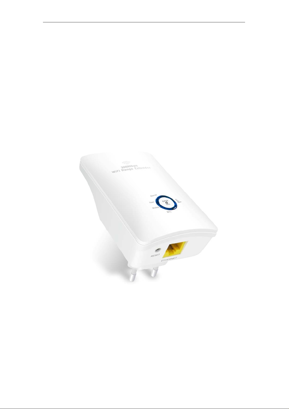
1. 11n Repeater
2. Quick Installation Guide
3. Ethernet Cable (RJ-45)
LED meanings & activations
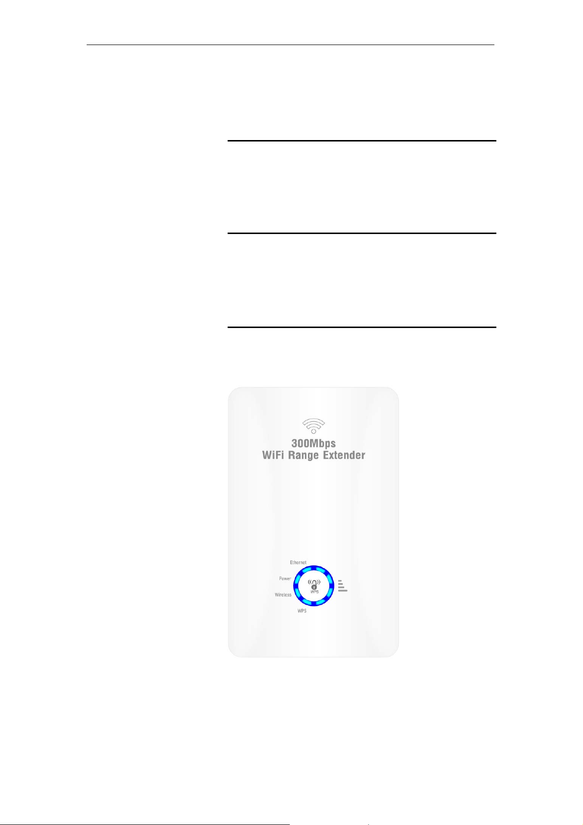
Top Side
The Top Side contains lights ca ll ed Lig ht E mitti ng Di o des (LE Ds)
that indicate the status of th e unit.
Figure 1: Top Side and LEDs
8
Page 9
11n Repeater User’s Manual
Label Color Functi on
Wifi Signal blue
Wireless blue
WPS blue
Ethernet blue
On Wireless Signal Strength
Off: No WLAN link
On: WLAN link established and active
Blink: Valid Wireless packet being transferred
Off: WPS link isn’t established and active
Blink: Valid WPS packet being transferred
On: LAN link established and active
Off: No LAN link
Blink: Valid Ethernet packet being transferred
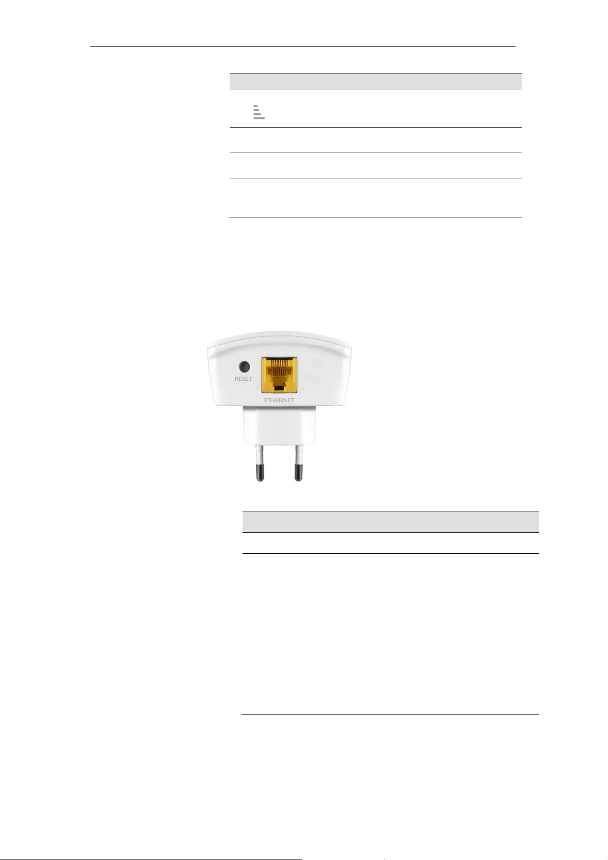
Rear and Left Panel and bottom Side
The rear and right panel and bottom side contains a Restore
Defaults button, the ports for the unit's data and power
connections.
Label Function
Ethernet Connects the device via LAN Ethernet to a PC
WPS / RESET
WPS
Press this button for 3 full seconds and the
WPS LED will flash to start WPS.
Now go to the wireless adapter or device and
press its WPS button. Make sure to press t he
button within 120 seconds (2 minutes) after
pressing the router's WPS button.
RESET
Reset button. RESET the 11n Repeater to its default
settings.
Press this button for at least 3 full seconds to RESE T
device to its default settings.
9
Page 10
11n Repeater User’s Manual
3 Computer configurations under different OS,
to obtain IP address automatically
Before starting the 11n Repeater configur ation, please ki ndly
configure the PC computer as below, to have automatic IP
address / DNS Server.
For Windows 98SE / ME / 2000 / XP
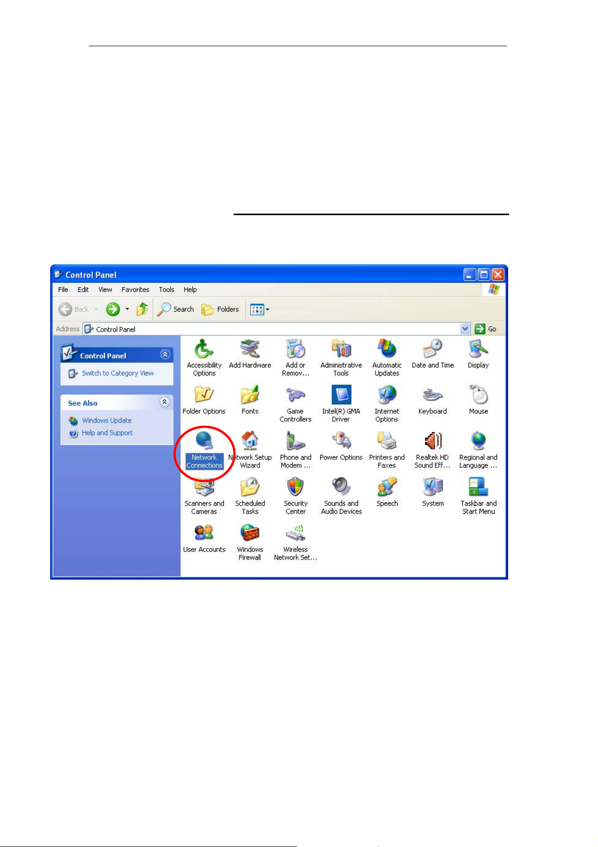
1. Click on "Start" -> "Control Panel" (in Classic View). In
the Control Panel, double click on "Network Connections"
to continue.
10
Page 11
11n Repeater User’s Manual
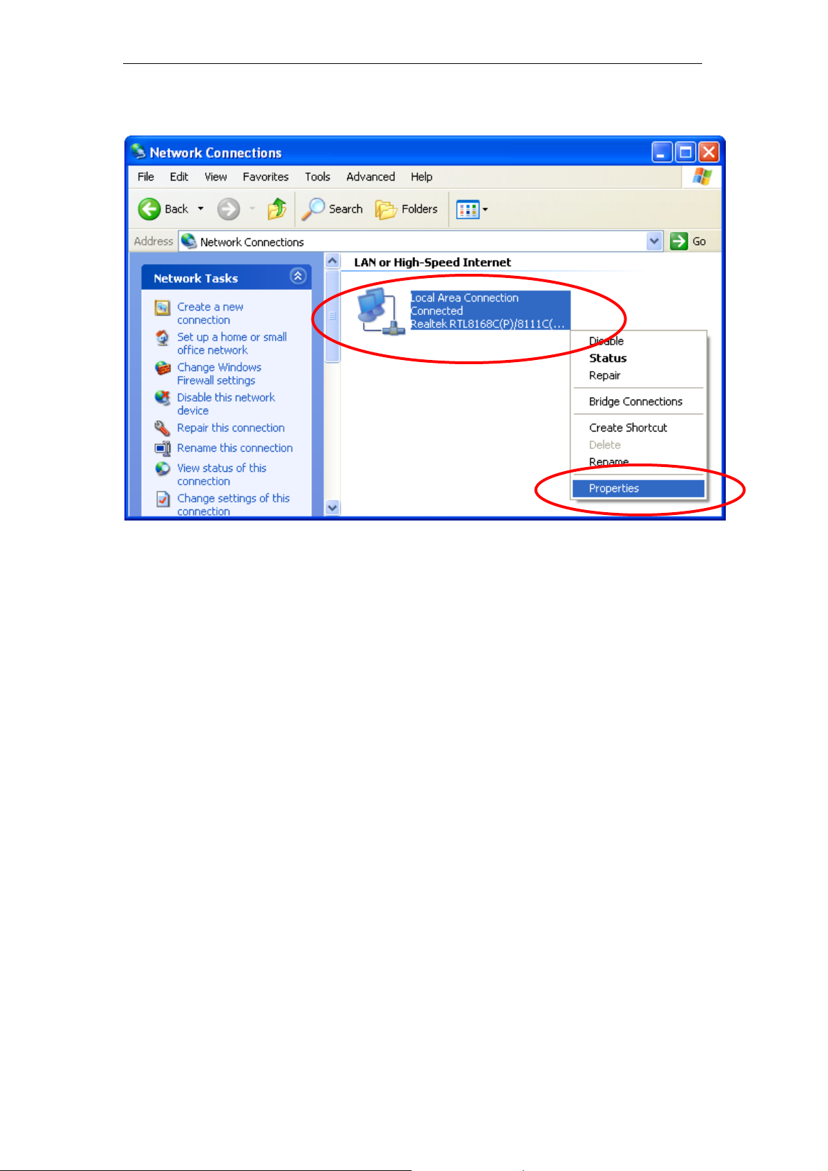
2. Single RIGHT click on "Local Area connection", then click
"Properties".
11
Page 12
11n Repeater User’s Manual
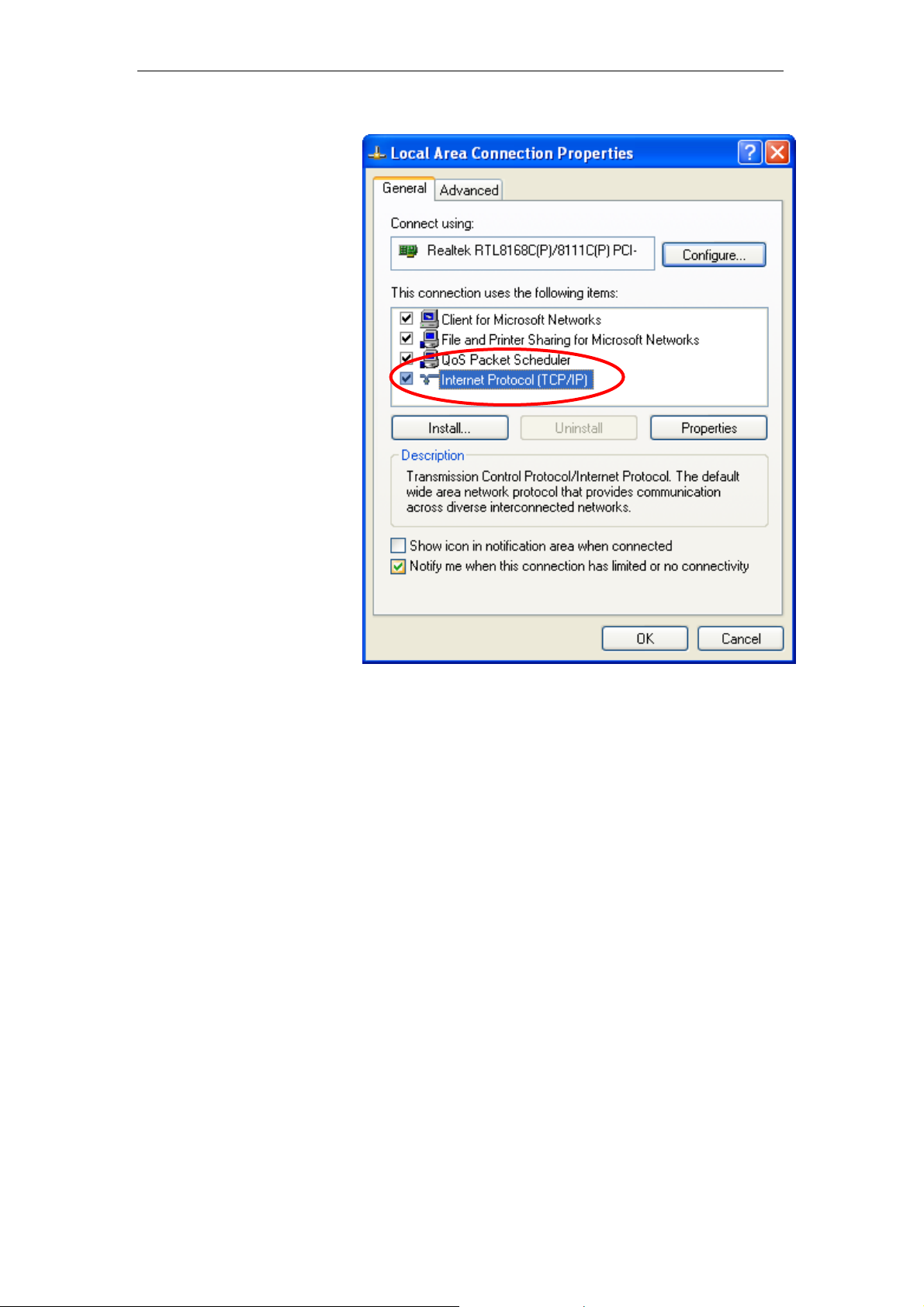
3. Double click on "Internet Protocol (TCP/IP)".
12
Page 13
11n Repeater User’s Manual
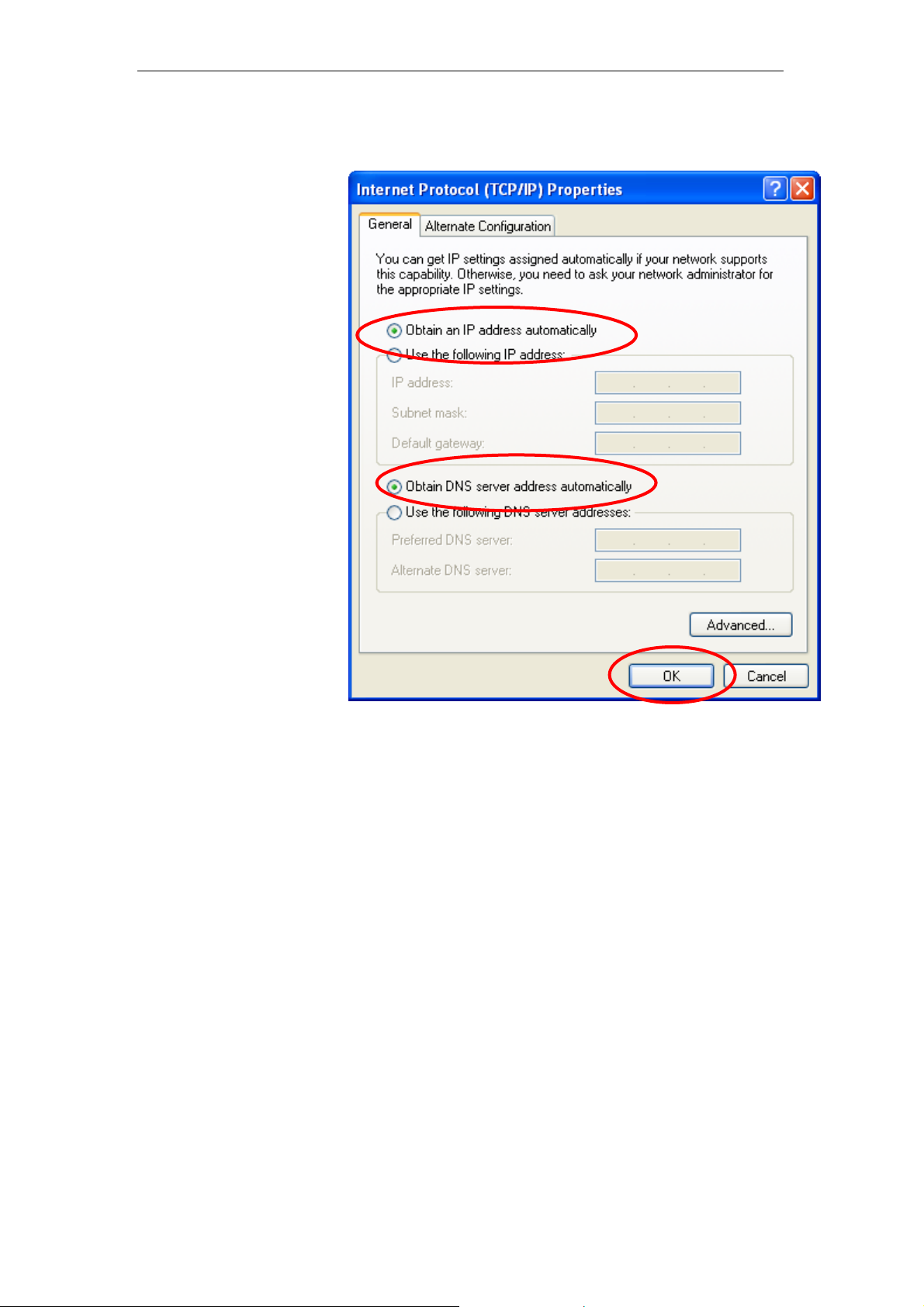
4. Check "Obtain an IP address autom atically " and "Obtain
DNS server address automatically" then click o n "OK" to
continue.
5. Click "Show icon in notification area when connected"
(see screen image in 3. above) then Click on "OK" to
complete the setup procedures.
13
Page 14
11n Repeater User’s Manual
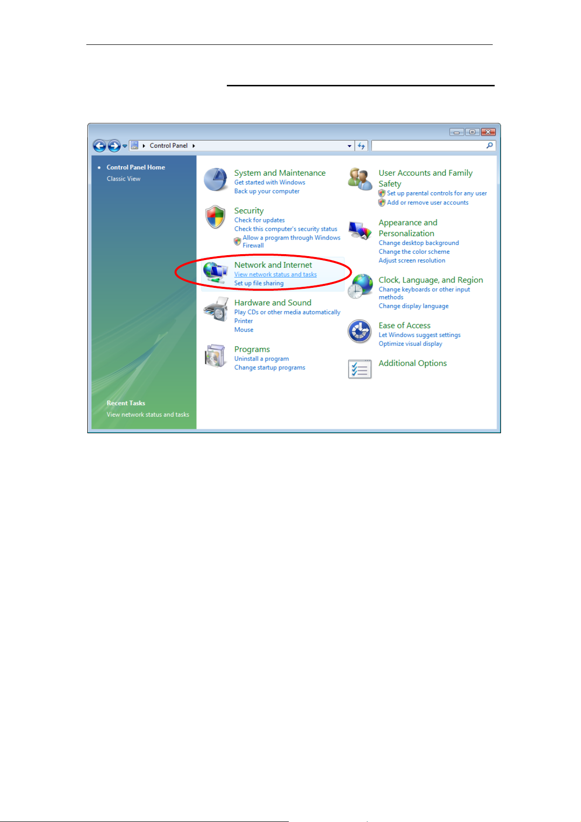
For Windows Vista-32/64
1. Click on “Start” -> “Control Panel” -> “View network
status and tasks”.
14
Page 15
11n Repeater User’s Manual
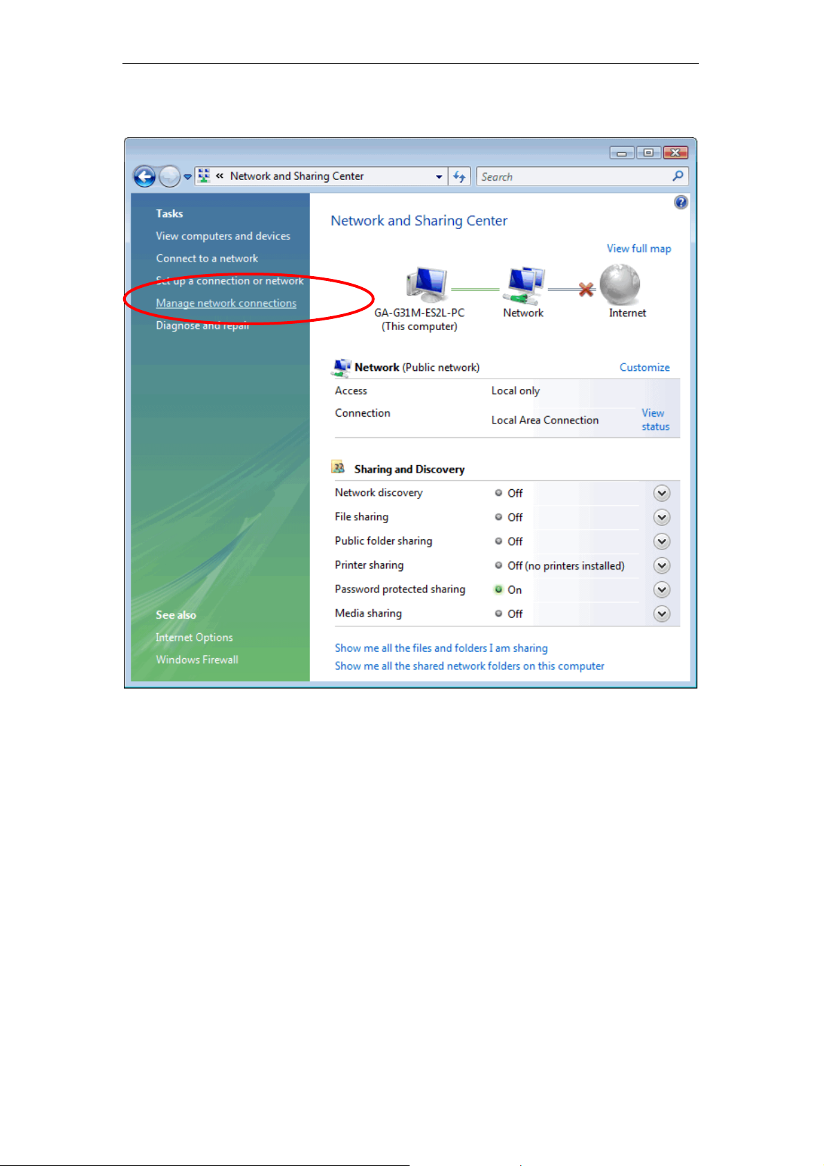
2. In the Manage network connections, click on “Manage
network connections” to continue.
15
Page 16
11n Repeater User’s Manual
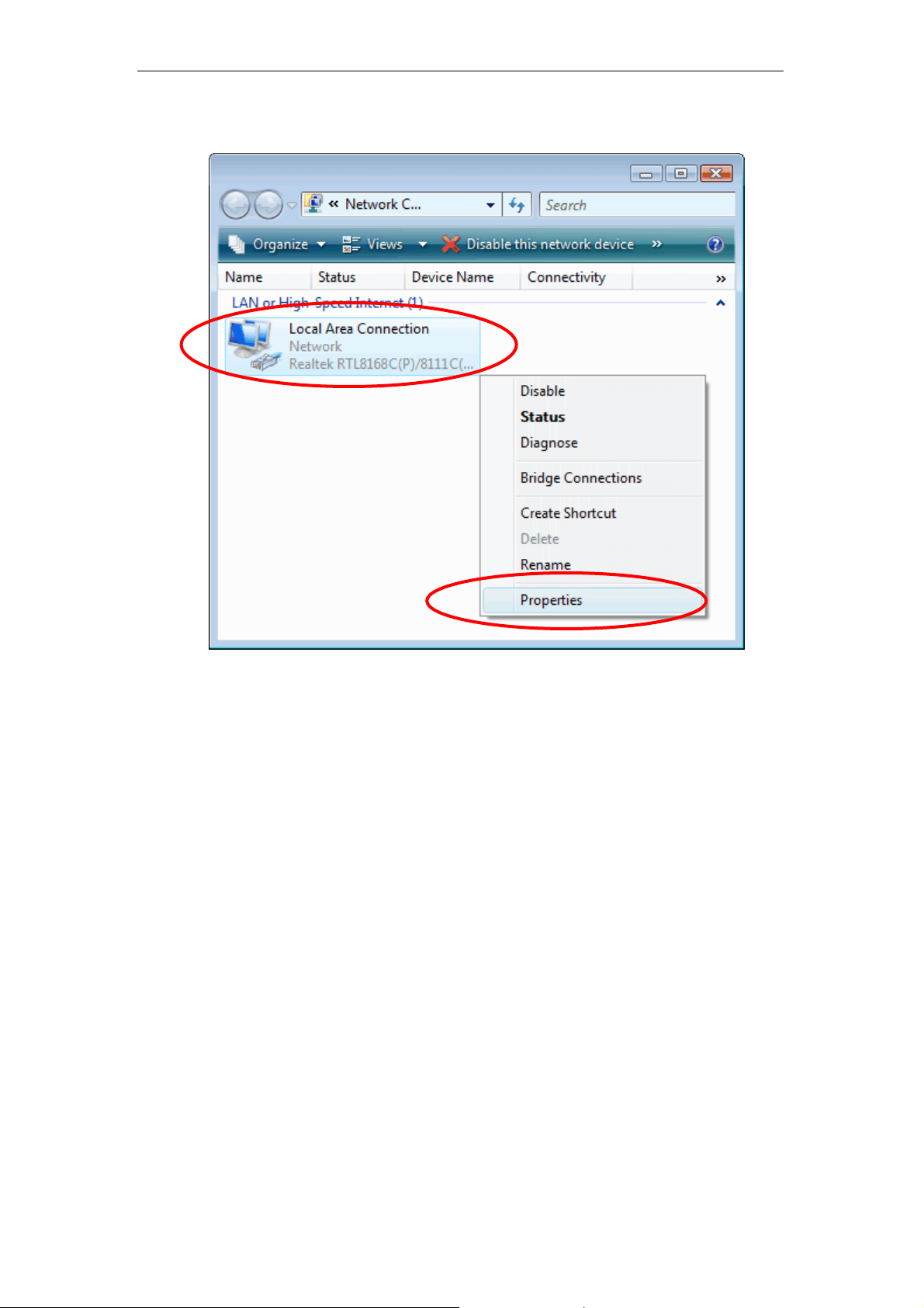
3. Single RIGHT click on "Local Area connection", then click
"Properties".
16
Page 17
11n Repeater User’s Manual
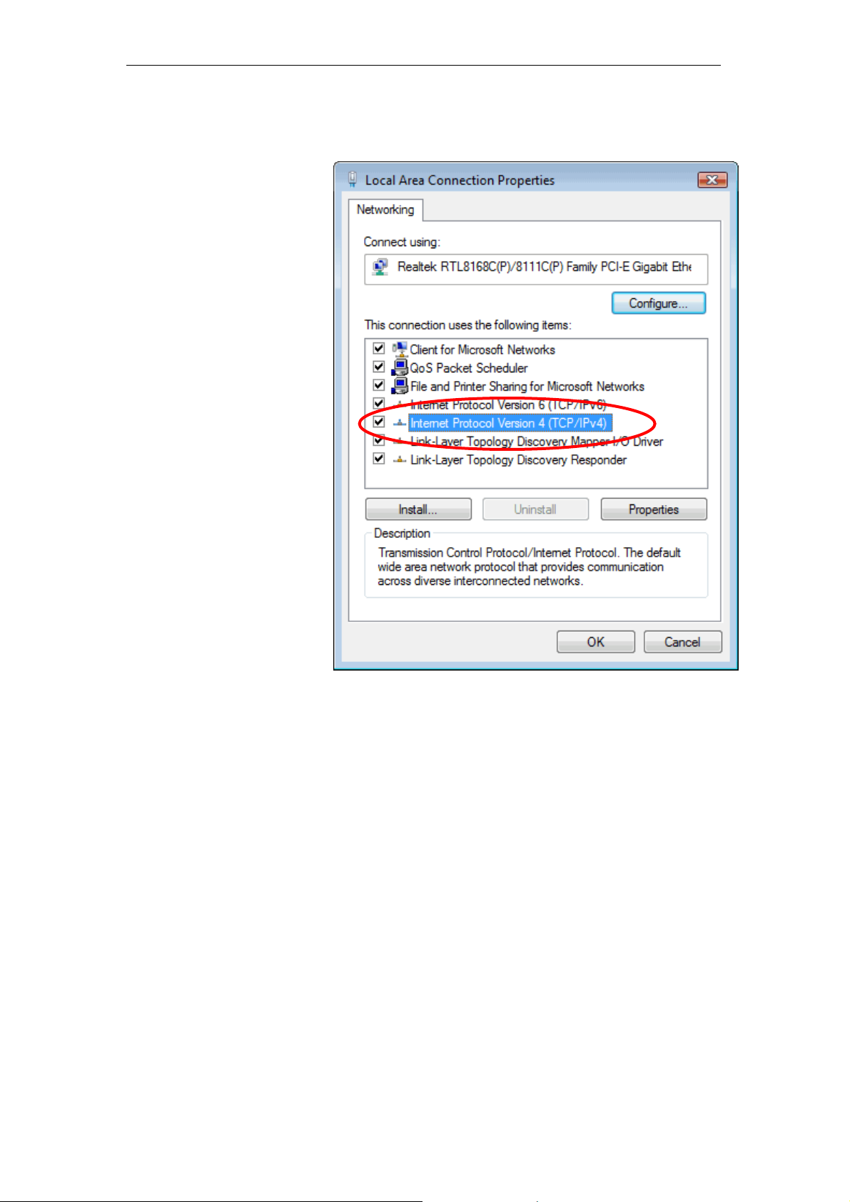
4. The screen wi ll display t he info rmation " User Account
Control" and click "Continue" to continue.
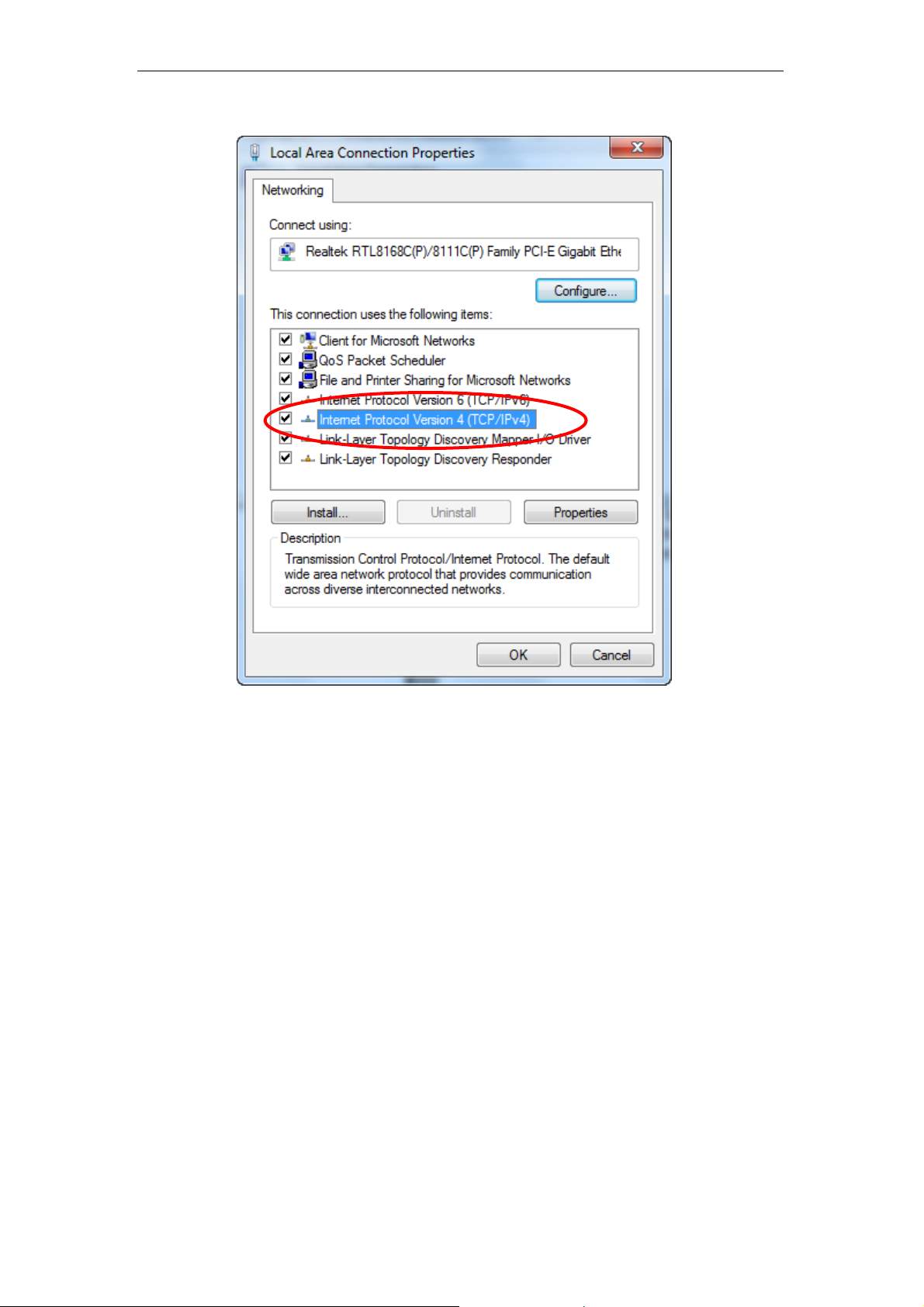
5. Double click on "Internet Protocol Version 4 (TCP/IPv4)".
17
Page 18
11n Repeater User’s Manual
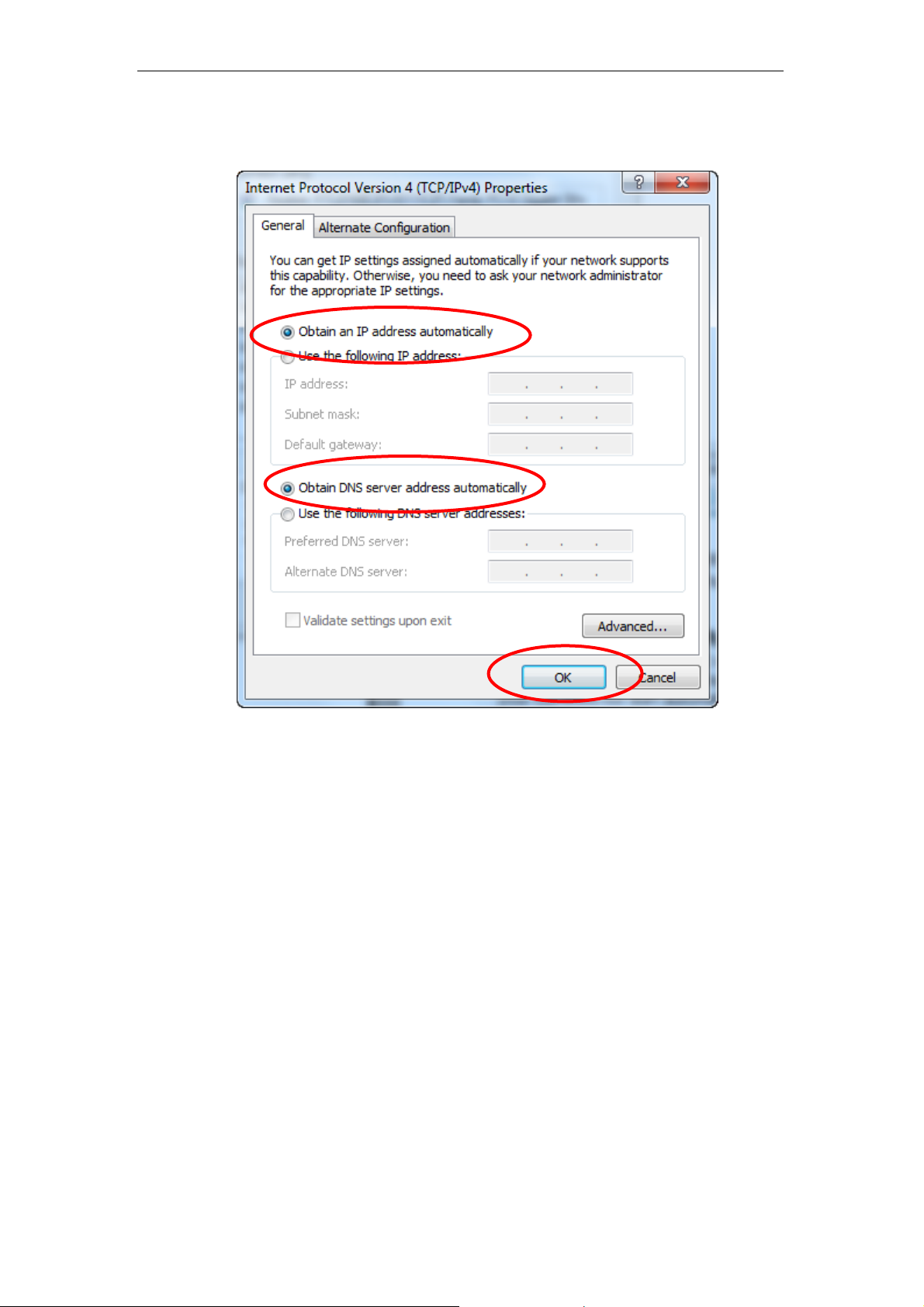
6. Check "Obtain an IP address autom atically " and "Obtain
DNS server address automatically" then click o n "OK" to
continue.
18
Page 19
11n Repeater User’s Manual
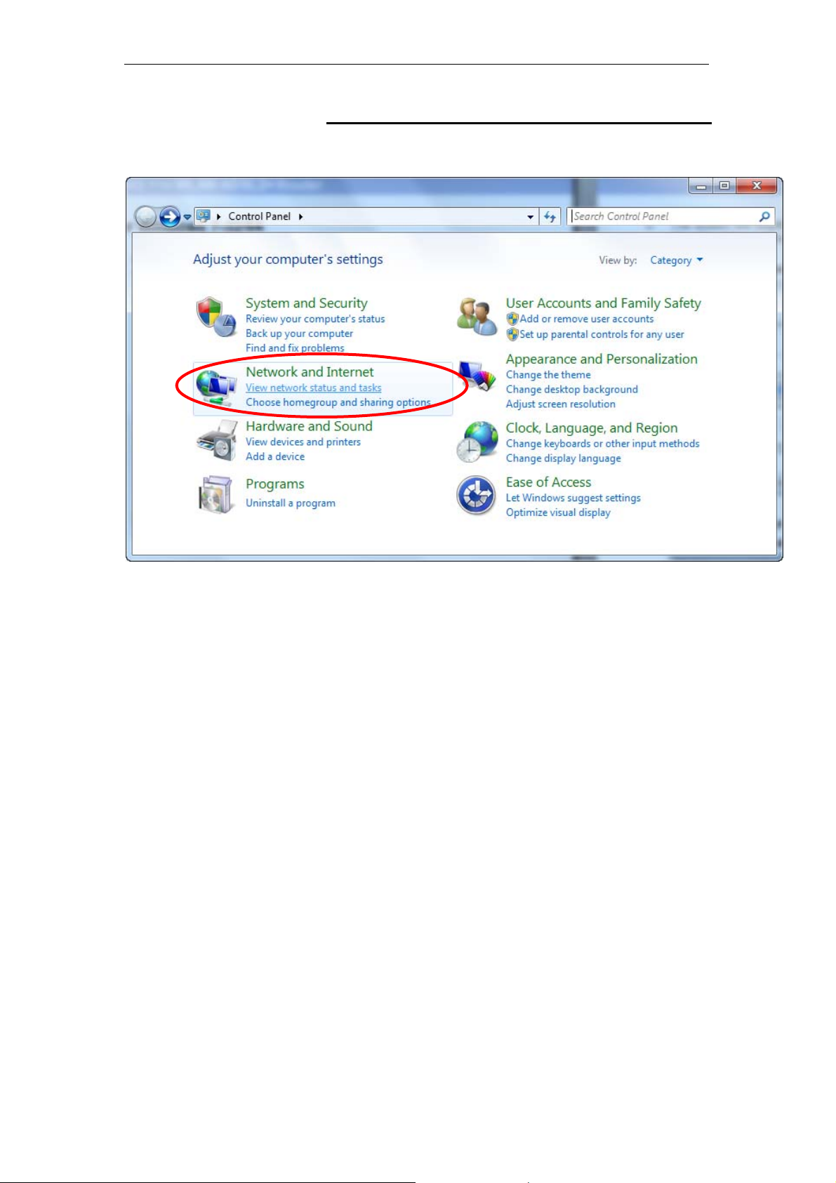
For Windows 7-32/64
7. Click on “Start” -> “Control Panel” (in Category View) ->
“View network status and tasks”.
19
Page 20
11n Repeater User’s Manual
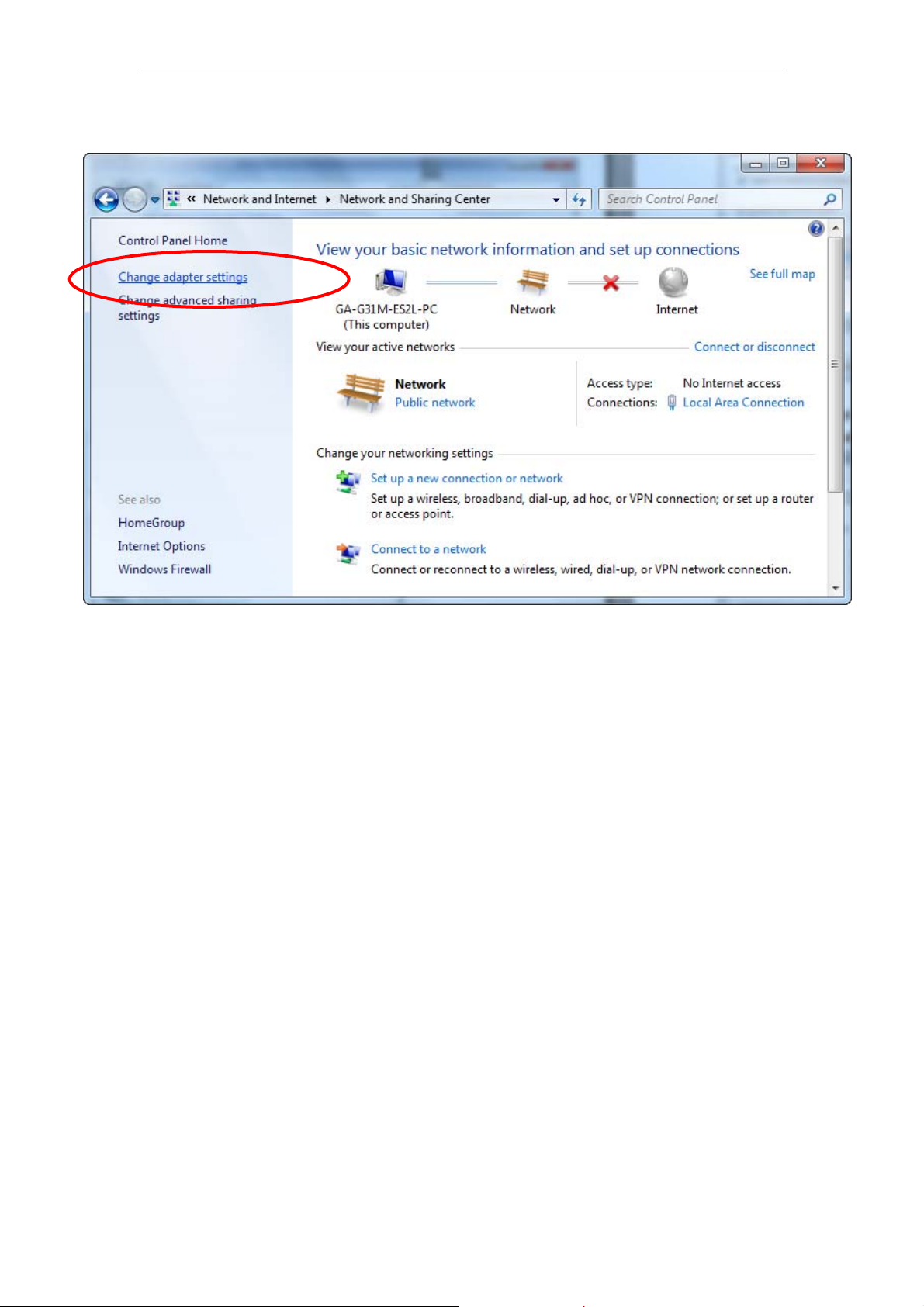
8. In the Control Panel Home, click on “Change adapter
settings” to continue.
20
Page 21
11n Repeater User’s Manual
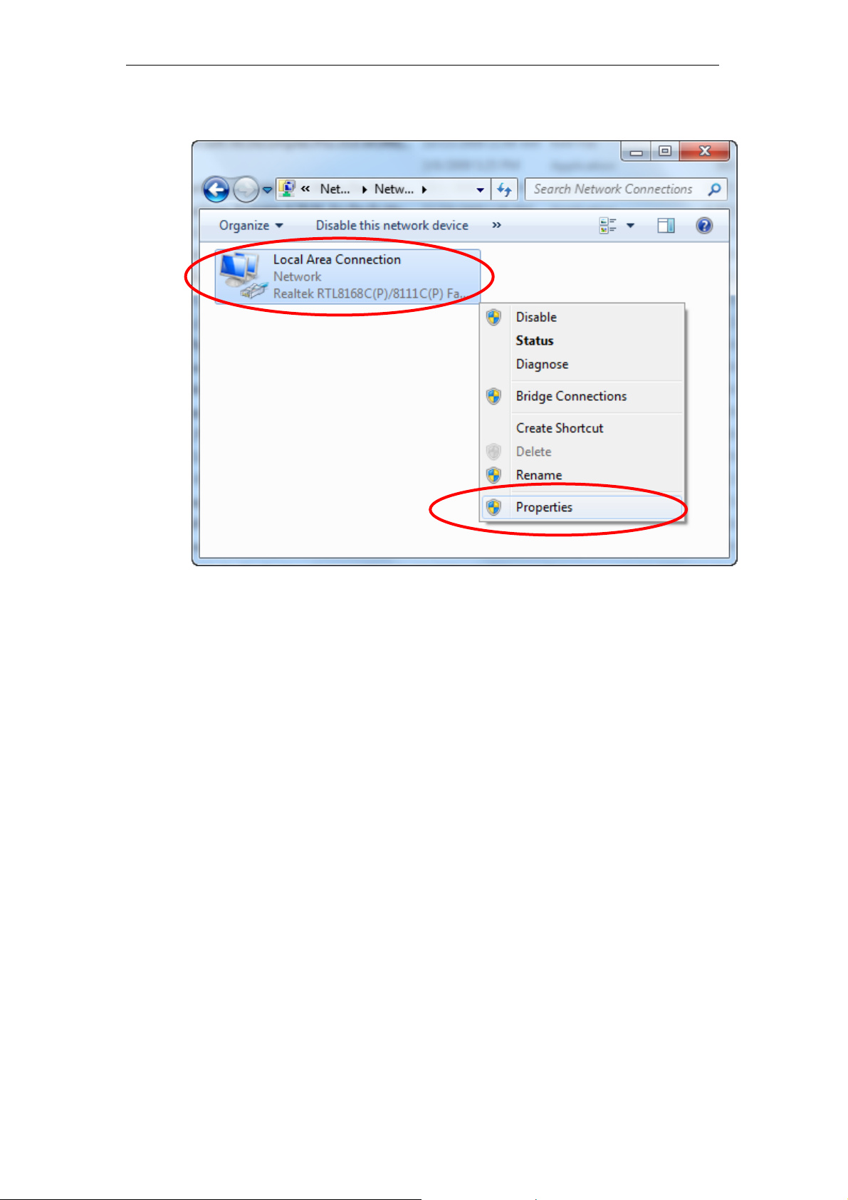
9. Single RIGHT click on “Local Area Connection”, then click
“Properties”.
21
Page 22
11n Repeater User’s Manual
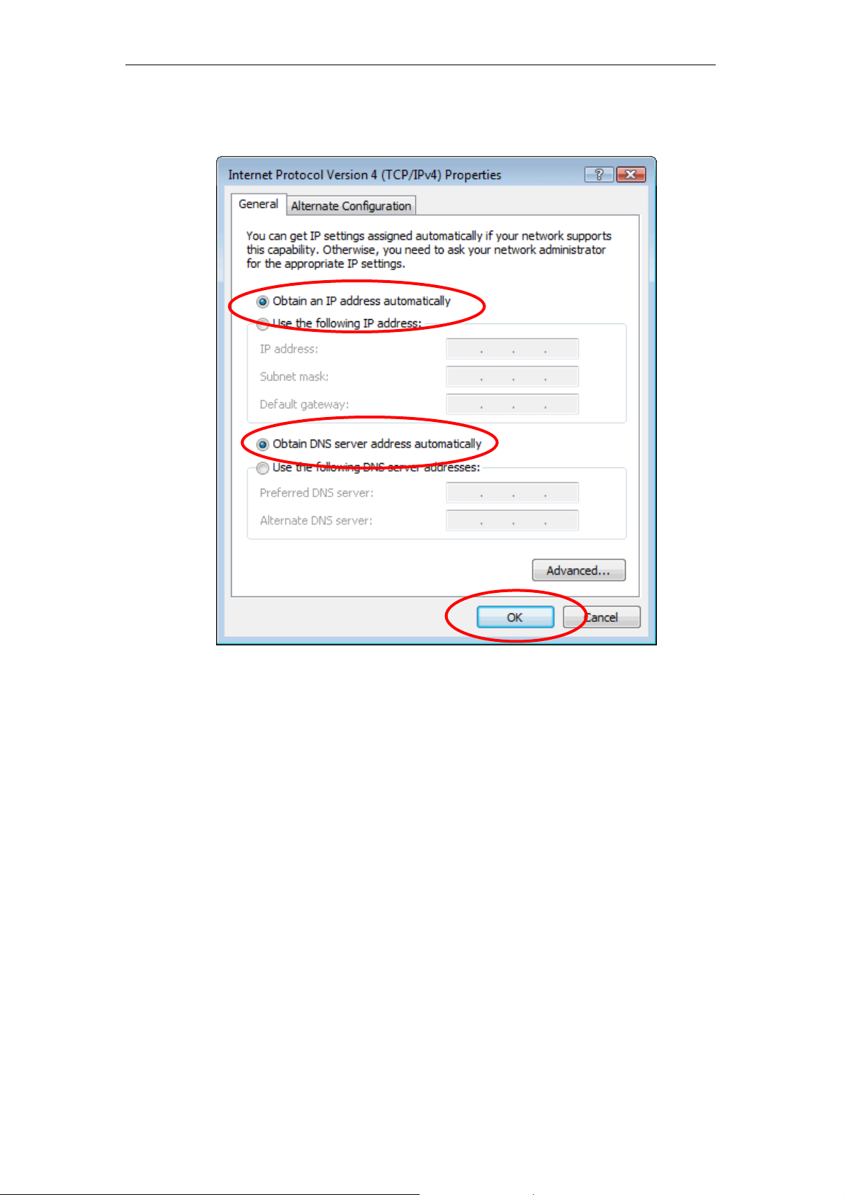
10. Double click on "Internet Protocol Version 4 (TCP/IPv4)".
22
Page 23
11n Repeater User’s Manual
11. Check "Obtain an IP address automatically" and "Obtain
DNS server address automatically" then click o n "OK" to
continue.
23
Page 24
11n Repeater User’s Manual
For Windows 8-32/64
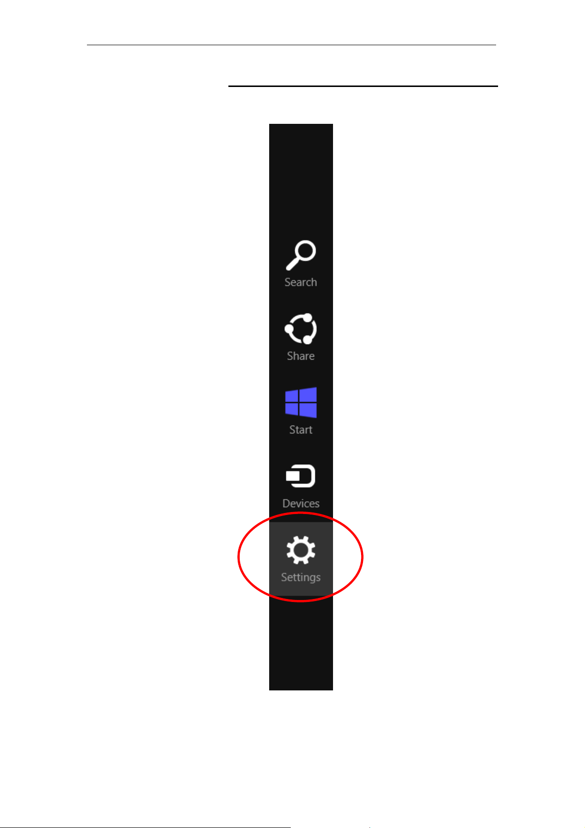
1. Move the mouse or tap to the upper right corner and click
on “Settings”.
24
Page 25
11n Repeater User’s Manual
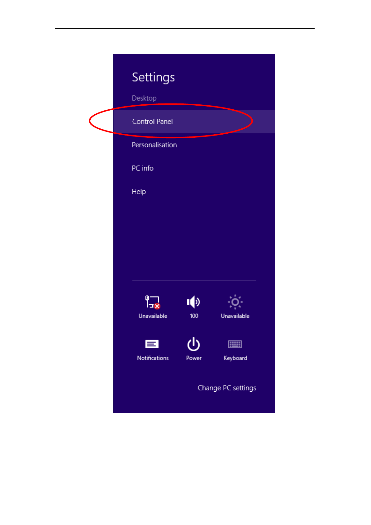
2. Click on “Control Panel”.
25
Page 26
11n Repeater User’s Manual
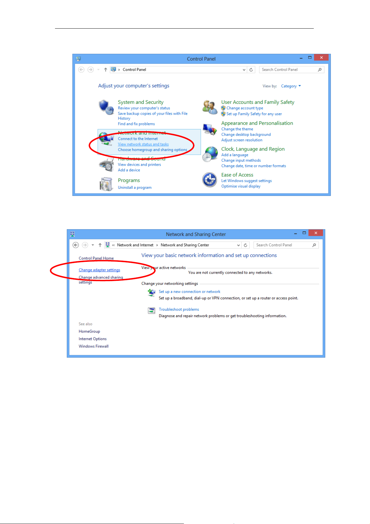
3. Click on “View network status and tasks”.
4. In the Control Panel Home, click on “Change adapter
settings” to continue.
26
Page 27
11n Repeater User’s Manual
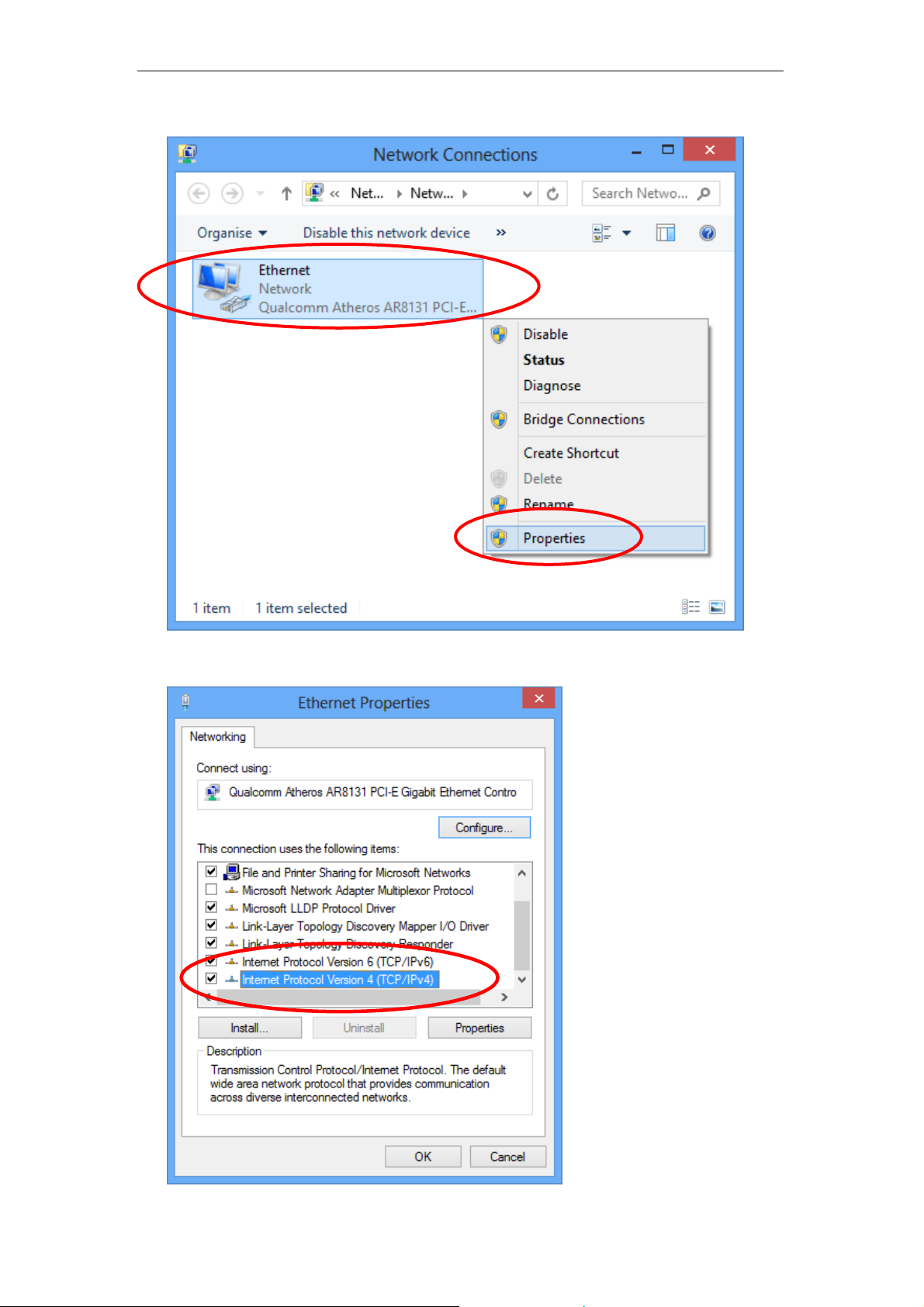
5. Single RIGHT click on “Ethernet", then click "Properties".
6. Double click on "Internet Protocol Version 4 (TCP/IPv4)".
27
Page 28
11n Repeater User’s Manual
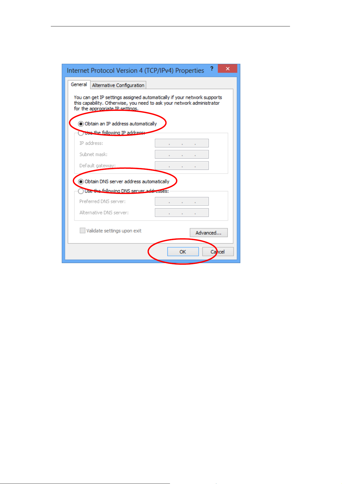
7. Check "Obtain an IP address automatically " and “ Obtain
DNS server address automatically” the n click on " OK" to
continue.
28
Page 29
11n Repeater User’s Manual
4 Connecting your device
This chapter provides basic instructions for connecting the
Wireless Gateway to a computer o r LAN an d to the I nternet.
In addition to configuring the devi ce, you nee d to config ure the
Internet properties of your computer(s). For m ore detail s, see
the following sections:
• Configuring Ethe rnet PCs
This chapter assumes that you have already esta blished a
DSL/Cable service with your Internet se rvice provider (I SP).
These instructions provide a basic configuration that should be
compatible with your home or small office network setup. Refer
to the subsequent chapters for additional configuration
instructions.
Connecting the Hardware
This section describes how to conne ct the device to t he wall
phone port, the power outlet and your comput er(s) or network.
Before you begin, turn the power off for all devices. These
include your computer(s), your LAN hub/ switch (if appli cable),
WARNING
and the Wireless Gateway.
The diagram below illustrates the hardware connections. The
layout of the ports on your device may va ry from the lay out
shown. Refer to the steps that follow for specific instructions.
Step 1. Connect the Ethernet cable to LAN Port
Connect the supplied RJ45 Ethernet cable from your PC's
Ethernet port to any of the 11n Repeater's LAN Port.
Step 2. Connect the 11n Repeater to your wall-moun ted
power outlet
29
Page 30

11n Repeater User’s Manual
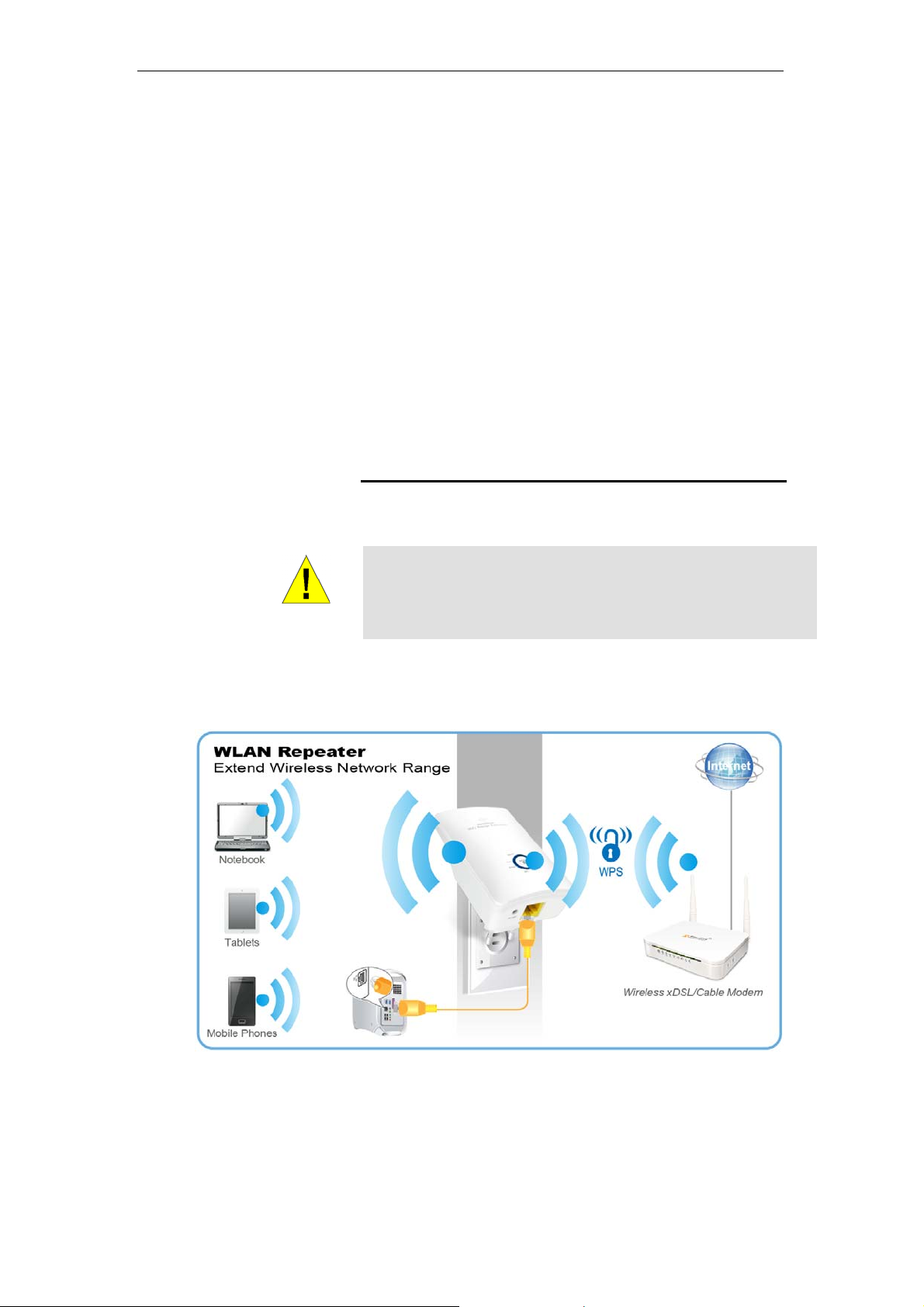
WPS Pairing between 11n Repeater and Wireless
xDSL/Cable Modem
This section describes how to do WPS Pairing between 11n
Repeater and Wireless xDSL/Cable.
The diagram below illustrates the hardware connections. The
layout of the ports on your device may va ry from the lay out
shown. Refer to the steps that follow for specific instructions.
Step 1. Press WPS button on Wireless xDSL/Cable Modem.
Step 2. Press WPS button on 11n Repeater for 3 seconds
and release WPS button. Now the WPS LED is blinking and
the 11n Repeater is donig WPS Pairing with Wireless
xDSL/Cable Modem.
Make sure to press the button within 120 se conds (2
minutes) after pressing the Wireless xDSL/Cable Modem's
WPS button.
Step 3. Once the 11n Repeater finished doing WP S Pairing
with Wireless xDSL/Cable Modem, the Wifi Signal Strength
LED is ON. The status of Wifi signal strength LED v aries
depending on the Wifi signal streng th bet ween 11n
Repeater and Wireless xDSL/Cable Modem.
Step 4. Check if the Wifi Signal Strength LED of 11n
Repeater is ON, the 11n Repeater is connected and suitable
for Internet Connections.
Step 5. Check if the Wifi Signal Strength is OFF, the 11n
Repeater isn’t connected and suitabl e for Internet
Connections. Please repeat steps of WPS Pairing or follow
next step to have it connected and suitable for Internet
Connections.
30
Page 31

11n Repeater User’s Manual
5 Advanced Configuration
Advanced Configuration
1. From any of the LAN computers connected to , launch your
web browser, type the following URL in the web addre ss (or
location) box, and press [Enter] on your keyboard:
http://10.0.0.2
2. Please enter t he Login User Name: admi n and Login
Password: administrator and then click o n Login button.
3. Check on “Auto” checkbox.
4. Click on “Site Survey” button and wait for 5 se conds for sit e
surveying.
31
Page 32

11n Repeater User’s Manual
5. Check on “Select” ratio of SSID of the front AP and
configure related parameters.
6. Click on “Apply&Save” button.
7. Click on “OK” button.
8. Now, the 11n Repe ater has been co nfigured compl eted,
and suitable for Wireless and Internet Connections.
32
Page 33

11n Repeater User’s Manual
Wireless Connection
For easy installation it is saved to keep the settings. Yo u can
later change the wireless settings via the wireless confi guration
menu.
9. Double click on the wireless icon on your computer and
search for the wireless network that y ou ente r SSID name.
10. Click on the wireless netwo rk that y ou ent er SSID name
(the default settings SSID = REPEATERXXXX which
could be found on the bottom side of the device) to
connect.
33
Page 34

11n Repeater User’s Manual
11. If the wireless network isn’t encrypted, click on "Connect
Anyway" to connect.
12. If the wireless network is encrypted, e nter y our own
wireless password at least 8 characters for example
12345678 in the key field / Network key field / Confirm
Network key field (the default setting s Secu rity Mode =
WPA/WPA2 Mixed, Pre-Shared Key = XXXXXXXX which
could be found on the bottom side of the device). You
can later change this network key via the wirel ess
configuration menu.
13. Click on "Connect" or "Ap ply".
14. Now you are ready to use the Wireless Network to Internet
or intranet.
34
Page 35

11n Repeater User’s Manual
6 What the Internet/W AN access of your own
Network now is
Now you could check what the Internet/WAN access of your
network is to know how to configure the WAN port of Wireless
Gateway.
Please follow steps below to check what the Internet/WAN
access if your own Network is DHCP Client, Static IP or PPPoE
Client.
1. Click Start -> Cont rol Panel
35
Page 36

11n Repeater User’s Manual
2. Double click Network Connections
36
Page 37

11n Repeater User’s Manual
Internet/WAN access is the DHCP client
If you cannot see any Broadband Adapter in the Net work
Connections, your Internet/WAN access is DHCP Client or
Static IP.
3. Click Local Area Connection in LAN or High-Speed
Internet and you could see string Assigned by DHCP in
Details.
37
Page 38

11n Repeater User’s Manual
Internet/WAN access is the Static IP
If you cannot see any Broadband Adapter in the Net work
Connections, your Internet/WAN access is DHCP Client or
Static IP.
4. Click Local Area Connection in LAN or High-Speed
Internet and you could see string Manually Configured in
Details.
38
Page 39

11n Repeater User’s Manual
5. Right click Local Area Connection and click Properties
and then you could get the IP settings in detail an d write
down the IP settings as follow:
IP Address: 192.168.10.110
Subnet mask: 255.255.255.0
Default gateway: 192.168.10.100
Preferred DNS server: 192.168.10.100
Alternate DNS Server: If you have it, please al so write it
down.
39
Page 40

11n Repeater User’s Manual
Internet/WAN access is the PPPoE client
If you can see any Broadband Adapter in the Network
Connections, your Internet/WAN access is PPPoE Client.
6. Click Broadband Adapter in Broadband and you could
see string Assigned by Service Provider in Details.
For PPPoE configuration on Wireless Gateway, you’ll ne ed
following information that you coul d get fr om your Tel ecom, or
by your Internet Service Provider.
Username of PPPoE: 1234 for example
Password of PPPoE: 1234 for example
40
Page 41

11n Repeater User’s Manual
7 Getting S tarted with the W eb pages
The Wireless Gateway includes a series of Web pages that
provide an interface to the software in stalled o n the devi ce. It
enables you to configure the device settings to meet the needs
of your network. You can access it through your web browser
from any PC connected to the device via
Accessing the Web pages
To access the Web pages, you need the following:
• A PC or laptop connected to the LAN port on the device.
• A web browser installed on the P C. The minimu m browser
version requirement is Internet Explorer v4 or Netscape v4.
For the best display quality, use latest version of Internet
Explorer, Netscape or Mozilla Fire fox. From any of the LAN
computers, launch your web browser, type the following
URL in the web address (or location) box, and press [Enter]
on your keyboard:
http://10.0.0.2
the LAN ports.
The Status homepage for the web pages is displayed:
Figure 2: Homepage
The first time that y ou click on a n entry from the l efthand menu, a login box is display ed. You must enter
your username and password to access the pages.
41
Page 42

11n Repeater User’s Manual
A login screen is displayed:
Figure 3: Login screen
1. Enter y our user nam e and pa ssword. The fi rst time yo u log
into the program, use these defaults:
admin
administrator
Note
User Name:
Password:
You can change the password at any time or you can configure your
device so that you do not need to enter a password. See Password.
2. Click on OK. You a re now ready to config ure your device.
This is the first page display ed ea ch time you log in t o the We b
pages.
Note
If you receive an error message or the Welcome page is not
displayed, see Troubleshooting Suggestions.
42
Page 43

11n Repeater User’s Manual
Testing your Setup
Once you have connected your hardware and configured your
PCs, any computer on your LAN should be able to use the DSL
/Cable connection to access the Internet.
To test the connection, turn on the device, wait for 30 seconds
and then verify that the LEDs are illum inated as follo ws:
Table 1. LED Indicators
Label Color Functi on
POWER green
WLAN green
LAN green
If the LEDs illuminate as expecte d, test your Int ernet co nnection
from a LAN computer. To do this, open your web browser, and
type the URL of any external website (such as
http://www.yahoo.com
rapidly and then appear solid as the device connects to the site.
On: device is powered on
Off: device is powered off
On: WLAN link established and active
Blink: Valid Wireless packet being transferred
On: LAN link established and active
Off: No LAN link
Blink: Valid Ethernet packet being transferred
). The LED labeled WAN should blink
WARNING
If the LEDs do not illuminate as expected, you may need to
configure your Internet access setting s using t he informa tion
provided by your ISP. For details, see Internet Access. If the
LEDs still do not illuminate as expected or the web page is n ot
displayed, see Troubleshooting Suggestions or contact your
ISP for assistance.
Default device settings
In addition to handling the xDSL / Cable modem connection to
your ISP, the Wireless Gateway can provide a variety of
services to your network. The device is preconfigured with
default settings for use with a typical home or small office
network.
The table below lists some of the m ost importa nt default settings;
these and other features are described f ully in the sub sequent
chapters. If you are familiar with net work conf iguration, review
these settings to verify that they meet the needs of your network.
Follow the instructions to change them if necessary. If you are
unfamiliar with these settings, t ry using t he device witho ut
modification, or contact your ISP for assistance.
We strongly recommend that you conta ct your ISP prior to
changing the default configuration.
43
Page 44

11n Repeater User’s Manual
Option Default Setting Explanation/Instructions
WAN Port IP
Address
DHCP Client
This is the temporary public IP address of the WAN
port on the device. It is an unnumbered interface that
is replaced as soon as your ISP assigns a ‘real’ IP
address. See Network Settings -> WAN Interface.
LAN Port
IP Address
Assigned static IP address:
10.0.0.2
Subnet mask:
This is the IP address of the LAN port on the device.
The LAN port connects the device to your Ethernet
network. Typically, you will not need to change this
address. See Network Settings -> LAN Inter face.
255.255.255.0
DHCP (Dynamic
Host Configuration
Protocol)
DHCP server enabled with the
following pool of addresses:
10.0.0.3
through
10.0.0.250
The Wireless Gateway maintains a pool of private IP
addresses for dynamic assignment to your LAN
computers. To use this service, you must have set up
your computers to accept IP information dynamically,
as described in Configuring Ethernet PCs.
44
Page 45

11n Repeater User’s Manual
8 Quick Setup
The Quick Setup page displays us eful inf ormati on about the
setup of your device, including:
• details of the device’ s Internet access settings
• details of the device’ s VoIP settings
• details of the device’s Wire less settin gs
To display this page:
From the head menu, click on Setup. The following page is
displayed:
Figure 4: Quick Setup page
45
Page 46

11n Repeater User’s Manual
Repeater Mode
Check on Repeater ratio
Check on Auto checkbox.
Click on Site Survey button and wait for 5 seconds for site
surveying.
46
Page 47

11n Repeater User’s Manual
Check on Select ratio of SSID of the front AP and configure
related parameters.
Click on Apply&Save button
3. WLAN mo de modifie d! System i s rebootin g now ...
4. Please wait 35 seco nds
47
Page 48

11n Repeater User’s Manual
9 LAN Interface
This chapter is to configure the paramete rs for local are a
network which connects to the LAN port of your Access Point.
Here you may change the setting for IP address, subnet mask,
DHCP, etc...
You should only change the addressing details if your ISP asks
Note
you to, or if you are familiar with network configuration. In most
cases, you will not need to make any changes to this
configuration.
LAN Interface Setup
To check the configuration of LAN Interface:
1. From the Setup menu, click on Local Network. The
following page is displayed:
48
Page 49

11n Repeater User’s Manual
Field Description
IP Address The IP address of your router on the local area network. Your local
area network settings are base d on the address as signed he re.
Subnet Mask The subnet mask of your router on the local area network.
DHCP Mode Once your router is properly configur ed and DHCP Server is
enabled, the DHCP Server will manage the IP addresses and ot her
network configuration informati on for computers a nd other dev ices
connected to your Local Area Net work. Th ere is n o need fo r you to
do this yourself.
The computers (and other devices) connected to your LAN also
need to have their TCP/IP configuration set to "DHCP" or "Obtain an
IP address automatically".
IP Pool Range These two IP values (from and to) define a range of IP addr esses
that the DHCP Server uses when assigning addresses to computers
and devices on your Local Area Net work. Any address es that a re
outside of this range are not managed by the DHCP Server; these
could, therefore, be used for manually configur ed devices or
devices that cannot use DHCP to obtain net work address details
automatically.
Your router, by default, has a static IP address of 192.168. 0.1. This
means that addresses 192.168.0.2 to 192.168.0.254 can be made
available for allocation by the DHCP Serv er.
Max Lease Time Th e amoun t of time that a comput er may have an IP addres s before
it is required to renew the lease. T he leas e functi ons jus t as a lease
on an apartment would. The initial lease des ignates the amo unt of
time before the lease expi res. If th e tenan t wishes to retain the
address when the lease is expir ed then a n e w lease is establi shed. If
the lease expires and the ad dress i s no long er neede d then another
tenant may use the addre ss.
Domain Name Domain name for the dhcp server scope.
DNS Servers DNS Server address for the dhcp se rver scope.
IP Address The IP address to be configured for your computer or device on the
local area network.For example, 192.168.0. 2.
Mac Address The mac address of your computer or dev ice on the local area
network.
49
Page 50

11n Repeater User’s Manual
Changing the LAN IP address and subnet mask
To Change the configuration of LAN Interface:
1. From the Setup menu, click on Local Network. The
following page is displayed:
50
Page 51

11n Repeater User’s Manual
2. Change the IP Address and Subnet Mask.
3. Click Apply Changes.
4. Click OK.
5. Type IP A ddress an d Change default LAN port IP address.
6. Click in the IP Address and Subnet Mask box and type a
new IP Address and Subnet Mask.
7. Change the default DHCP Client Range.
8. Click Apply Changes.
51
Page 52

11n Repeater User’s Manual
You may also need to renew your DHCP lease:
Windows 95/98
a. Select Run... from the Start menu.
b. Enter winipcfg and clic k OK.
c. Select your ethernet adaptor from the pull-down menu
d. Click Release All and then Renew All.
e. Exit the winipcfg dialog.
Windows NT/Windows 2000/Windows XP
a. Bring up a command window.
b. Type ipconfig /release in the command window.
c. Type ipconfig /renew.
d. Type exit to close the command window.
Linux
a. Bring up a shell.
Note
b. Type pump -r to release the lease.
c. Type pump to renew the lease.
If you change the LAN IP address of the device while conne cted
through your Web browser, you will be disconnected. You must
open a new connection by entering your new LAN IP address as
the URL.
52
Page 53

11n Repeater User’s Manual
DHCP Static IP Configuration
If you need to assign static ip for your computer or device on the
local area network, configure static ip wit h the mac addre ss.:
1. From the Setup menu, click on Local Network. The
following page is displayed:
53
Page 54

11n Repeater User’s Manual
2. Enter the IP Address.
3. Enter the Mac Address.
4. Click Add.
5. The DHCP St atic IP Config uration that y ou create d has
been added in the DHCP Static IP Table.
54
Page 55

11n Repeater User’s Manual
10 Wireless Network
This chapter assumes that you have already set up your
Wireless PCs and installed a co mpatible Wi reless card on y our
device. See Configuring Wireless P Cs.
Wireless Basics
The Wireless Network page allows you to configure the
Wireless features of your dev ice. To acce ss the Wireless Basics
page:
From the Wireless menu, click on Wireless Basics. The
following page is displayed:
Figure 5: Wireless Network page
55
Page 56

11n Repeater User’s Manual
Field Description
Enable SSID
Broadcast
Enable Wireless
Isolation
Broadcast or Hide SSID to your Network.
Default: Enabled
Isolate your Network.
Default: Disabled
SSID Specify the network name.
Each Wireless LAN network uses a unique Network Name to identify
the network. This name is call ed the Serv ice Set I dentifi er (SSI D). Whe n
you set up your wireless adapter, y ou speci fy the SSID. If y ou want to
connect to an existing network, you must use th e name for that
network. If you are setting up y our o wn net work you can ma ke up y our
own name and use it on each computer. The name can be up to 20
characters long and contain letter s and numbe rs.
Mode Specify the WLAN Mode to 802.11b mode, 802.11g mode, 802.11b/g
mode, 802.11n mode, 802.11n/g mode or 802.11b/g/ n mode
Channel Choose a Channel from the pull-down menu.
Band Width Choose a Band Width from the pull-down menu.
Max
Select the Max Transmission Rate from the drop -down list
Transmission
Rate
Security Options Configure the Encryption to None, WE P, WPA-PSK[TKIP] , WPA2-
PSK[AES] or WPA-PSK/WPA2-PSK AE S
Security
Encryption(WEP)
Security
Authentication Type: Au toma tic or Shared Key s
Encryption Strength: 64 bits or 128 bits
Select and configure Key 1, Key 2, Key 3 o r Key 4
Encryption(WEP)
Key
Security
Enter the Pre-Shared Key
Options(WPAPSK)
Security
Enter the Pre-Shared Key
Options(WPA2PSK)
Security
Enter the Pre-Shared Key
Options(WPAPSK+WPA2PSK)
56
Page 57

11n Repeater User’s Manual
Wireless Advanced Settings
This page helps you to setup advanced wireless features,
include Fragment Threshold etc.
From the Wireless menu, click on Wireless Advanced. The
following page is displayed:
Field Description
Fragment
Threshold
When transmitting a packet over a network medium, sometimes the
packet is broken into several segments, if the size of packet exceeds
that allowed by the network medium.
The Fragmentation Threshold defi nes the number of by tes used for the
fragmentation boundary for directed messages.
RTS Threshold RTS stands for “Request to Send”. This parameter controls what size
data packet the low level RF protocol issues to an RTS packet. The
default is 2347.
Preamble Type This is the length of the CRC (Cyclic Redundancy Check) block for
communication between the router and wireless clients. High network
traffic areas should sel ect Shor t pream ble ty pe.
Radio Power
TX Power measurement.
(Percent)
HT20/40
Disable or Enable 20/40MHz Coexist
Coexistence
Enable WPS Disable or Enable WPS
Disable PIN Disable or Enable PIN
Keep current Disable or Enable current configuration
57
Page 58

11n Repeater User’s Manual
configuration
Wireless Access Control Mode
For security reason, using MAC ACL's (MAC Address Access
List) creates another level of difficulty to ha cking a networ k. A
MAC ACL is created and distributed to AP so that only
authorized NIC's can connect to the network. Wh ile MAC
address spoofing is a proven means to hacking a network this
can be used in conjunction with additional security measures to
increase the level of complexity of the network security
decreasing the chance of a breach.
MAC addresses can be add/delete/edit from the ACL list
depending on the MAC Access Policy.
If you choose 'Allowed Listed', only those clients whos e wireless
MAC addresses are in the access control list will be able to
connect to your Access Point. When 'Deny Listed' is selected,
these wireless clients on the list will not be able to connect the
Access Point. To access the Wireless Network Access Control
page:
From the Wireless menu, click on Wireless Advanced and then
click on ACL Setup button. The following page is displayed:
58
Page 59

11n Repeater User’s Manual
Allow Listed
If you Enable Wireless Access Control Mode, only those client s
whose wireless MAC addresses are in the access control list
will be able to connect to your Access Point.
1. Enable Wireless Access Control Mode.
2. Click Apply button.
3. Click OK button.
4. Enter the MAC Address.
5. Click Add button.
59
Page 60

11n Repeater User’s Manual
6. The MAC Address that you created has been added in the
Access Control List.
60
Page 61

11n Repeater User’s Manual
11 Reboot/Reset
Restarts the device with current setting or default setting.
Reboot/Reset
1. From the Maintenance -> Reboot menu. The following page
is displayed:
Fields on the
first setting
block
Reboot Restarts the router for the settings to take effect.
Reset Restarts the router with factory default setting.
Description
61
Page 62

11n Repeater User’s Manual
12 Firmware Upgrade
About firmware versions
Firmware is a software program. It is stored as read-only
memory on your device.
Your device can check whether there are later firm ware
versions available. If there is a later version, you can download
it via the Internet and install it o n your device.
Note
If there is a firmware update available you are strongly advised to
install it on your device to ensure that you take full advantage of
any new feature developments.
Manually updating firmware
You can manually download the latest firmwa re version f rom
provider’s website to your PC’s file directory.
Once you have downloaded the latest firm ware versi on to your
PC, you can manually select and install it as follows:
1. From the Maintenance -> Firmware Upgrade menu. The
following page is displayed:
2. Click on the Browse… button.
3. Once you have selected the file to be installed, click Open.
The file’s directory path is displayed in the New Fi rmwa re
Image: text box.
4. Click Automatically reset default after firmware upgraded.
5. Click Upload.
Figure 6: Manual Update Installation section
(Note that if you are using certain browsers (such as Opera
7) the Browse button is labeled Choose.)
Use the Choose file box to navigate to the relev ant dire ctory
where the firmware version is saved.
62
Page 63

11n Repeater User’s Manual
6. Click OK.
7. The device checks that the selected file contains an
updated version of firmware. A status screen pops up,
please wait for a while…….
8. The device checks that the selected file contains an
updated version of firmware. A status screen pops up,
please wait for a while…….
63
Page 64

11n Repeater User’s Manual
13 Backup/Restore Settings
This page allows you save current settings to a f ile or rel oad the
settings from the file which was sav ed previ ously.
Besides, you could reset the current configuration t o factory
default.
If you do make changes to the default configuration but then
wish to revert back to the origi nal fact ory config uration, y ou can
do so by resetting the device to factory default s.
Save Settings to File
It allows you save current settings to a file.
1. From the Maintenance -> Backup/Restore menu. The
following page is displayed:
Figure 7: Reset to Defaults page
Option Description
Save Settings
to File
Load Settings
from File
Save the Settings to a File
Load Settings from a File
2. Click on Save….
64
Page 65

11n Repeater User’s Manual
3. If you are happy with this, click Save and then browse to
where the file to be saved. Or click Cancel to cancel it.
Load Settings from File
It allows you to reload the setti ngs fr om the fil e which was sav ed
previously.
4. From the Maintenance -> Backup/Restore menu. The
following page is displayed:
5. Click on Browse….to browse to where the config.im g is.
65
Page 66

11n Repeater User’s Manual
6. If you are happy with this, click Upload to start to load
settings from file.
7. If you are happy with this, click Upload to start to load
settings from file.
8. please wait for a while…….
66
Page 67

11n Repeater User’s Manual
14 Password
You can restrict access to your device’s web pages using
password protection. With password protection enabled, users
must enter a username and password before gaining acce ss to
the web pages.
By default, password protection is enable d on your dev ice, an d
the username and password set are as follows:
Username: admin
Password: administrator
Setting your username and password
Note
Non-authorized users may try to access your system by guessing
your username and password. We recommend that yo u change
the default username and password to your own unique settings.
To change the default password:
1. From the Maintenance -> Password menu. The following
page is displayed:
67
Page 68

11n Repeater User’s Manual
2. This page displays the current username and password
settings. Change your own unique password in the relev ant
boxes. They can be any combination of letters or numbers
with a maximum of 30 characters. The default setting uses
admin for the username and administrator for password.
3. If you are happy with these settings, click Modify. You will
see following page that the new user has bee n displaye d on
the Currently Defined Users. You need to login to t he web
pages using your new username and new password.
4. Click on the ratio of admin from User Account Table.
5. Enter the Old Password.
6. Enter the New Password.
7. Enter the Confirm Password.
8. Click on Modify.
68
Page 69

11n Repeater User’s Manual
15 T ime and Date
Certain systems may not have a date or t ime mecha nism or
may be using inaccurate time/day information. the Simple
Network Time Protocol feature p rovides a way to sy nchron ize
the device’s own time of day setting with a remote time server
as described in RFC 2030 (SNTP) and RFC 1305 (NTP).
Time and Date Configuration settings
1. From the Maintenance -> Time and Date menu. The
following page is displayed:
69
Page 70

11n Repeater User’s Manual
2. Check the option State.
3. Configure the Server.
4. From the Time Zone drop-down list, select Your Own Time
Zone.
5. Click Apply Changes.
70
Page 71

11n Repeater User’s Manual
16 S tatus
This page displays the current inform ation for t he device. It will
display the LAN, WAN, and system firmware informatio n. This
page will display different information, according to WAN setting
(Static IP, DHCP, or PPPoE).
1. From the Status -> Device Info menu. The following page is
displayed:
71
Page 72

11n Repeater User’s Manual
17 Active Client Table
This page shows the computers, identified by the name and
MAC address that have acquired IP addresses by the DHCP
server with the time that the lease for the IP address is up
1. From the Status -> Active Client Table menu. The following
page is displayed:
72
Page 73

11n Repeater User’s Manual
18 S tatistics
This page shows the packet statistics for transmission and
reception regarding to netw ork inte rfac e.
1. From the Status -> Statistics menu. The following page is
displayed:
73
Page 74

11n Repeater User’s Manual
A Configuring your Computers
This appendix provides instructions for configuring the Internet
settings on your computers to work with the Wireless Gateway.
Configuring Ethernet PCs
Before you begin
By default, the Wireless Gateway automatically assigns the
required Internet settings to your PCs. You need t o config ure
the PCs to accept this information when it is assigned.
In some cases, you may wa nt to assign Internet information
manually to some or all of your computers rather than allow the
Note
Wireless Gateway to do so. See Assigning static Internet
information to your PCs for instructions.
• If you have connected your LAN PCs vi a Ethern et to the
Wireless Gateway, follow the instructions that correspond to
the operating system installed on you r PC:
• Windows® XP PCs
• Windows 2000 PCs
• Windows Me PCs
• Windows 95, 98 PCs
• Windows NT 4.0 workstations
Windows® XP PCs
1. In the Windows task bar, click the Start button, and then
click Control Panel.
2. Double-click the Network Connections icon.
3. In the LAN or High-Speed Internet window, right-cli ck on
the icon corresponding to your network interface card (NIC)
and select Properties. (Often, this icon is labeled Local Area
Connection).
The Local Area Connection dialog box is displayed with a
list of currently installed network ite ms.
4. Ensure that the check box to the left of the item labeled
Internet Protocol TCP/IP is checked and click Properties.
5. In the Internet Protocol (TCP/IP) Properties dialog box, click
the radio button labeled Obtain an IP address automatically.
Also click the radio button labeled Obtain DNS server
address automatically.
6. Click OK twice to confirm your changes, and then close th e
Control Panel.
Windows 2000 PCs
First, check for the IP protocol and, if n ecessary, in stall it:
1. In the Windows task bar, click the Start button, point to
Settings, and then click Control Panel.
2. Double-click the Network and Dial-up Connections icon.
74
Page 75

11n Repeater User’s Manual
3. In the Network and Dial-up Connections window, right-click
the Local Area Connection icon, and then select Properties.
The Local Area Connection Properties dialog box is
displayed with a list of currently installed netwo rk
components. If the list includes Internet Protocol (TCP/IP),
then the protocol has already been enabled. Skip to step 10.
4. If Internet Protocol (TCP/IP) does not display as an installed
component, click Install…
5. In the Select Network Component Type dialog box, select
Protocol, and then click Add…
6. Select Internet Protocol (TCP/IP) in the Network Protocols
list, and then click OK.
You may be prompted to install files from your Windows
2000 installation CD or othe r media. Foll ow the instructi ons
to install the files.
7. If prompted, click OK to restart your computer with the new
settings.
Next, configure the PCs to accept IP info rmation assig ned by
the Wireless Gateway:
8. In the Control Panel, double-click the Network and Dial-up
Connections icon.
9. In the Network and Dial-up Connections window, right-click
the Local Area Connection icon, and then select Properties.
10. In the Local Area Connection Properties dialog box, select
Internet Protocol (TCP/IP), and the n click Properties.
11. In the Internet Protocol (TCP/IP) Properties dialog box, click
the radio button labeled Obtain an IP address automatically.
Also click the radio button labeled Obtain DNS server
address automatically.
12. Click OK twice to confirm and save your changes, and then
close the Control Panel.
75
Page 76

11n Repeater User’s Manual
Windows Me PCs
1. In the Windows task bar, click the Start button, point to
Settings, and then click Control Panel.
2. Double-click the Network and Dial-up Connections icon.
3. In the Network and Dial-up Connections window, right-click
the Network icon, and then select Properties.
The Network Properties dialog box displays with a list of
currently installed network compo nents. I f the li st inclu des
Internet Protocol (TCP/IP), then the prot ocol has alrea dy
been enabled. Skip to step 11.
4. If Internet Protocol (TCP/IP) does not display as an installed
component, click Add…
5. In the Select Network Component Type dialog box, select
Protocol, and then click Add…
6. Select Microsoft in the Manufacturers box.
7. Select Internet Protocol (TCP/IP) in the Network Protocols
list, and then click OK.
You may be prompted to install files from your Windows Me
installation CD or other medi a. Follow t he in struction s to
install the files.
8. If prompted, click OK to restart your computer with the new
settings.
Next, configure the PCs to accept IP info rmation assig ned by
the Wireless Gateway:
9. In the Control Panel, double-click the Network and Dial-up
Connections icon.
10. In Network and Dial-up Connections window, right-click the
Network icon, and then select Properties.
11. In the Network Properties dialog box, select TCP/IP, and
then click Properties.
12. In the TCP/IP Settings dialog box, click the radio button
labeled Server assigned IP address. Also click the radio
button labeled Server assigned name server address.
13. Click OK twice to confirm and save your changes, and then
close the Control Panel.
Windows 95, 98 PCs
First, check for the IP protocol and, if n ecessary, in stall it:
1. In the Windows task bar, click the Start button, point to
Settings, and then click Control Panel.
2. Double-click the Network icon.
The Network dialog box display s with a list of currently
installed network components. If the list includes TCP/IP,
and then the protocol has already been enabled. Skip to
step 9.
3.
If TCP/IP does not display as an installed component, click
Add…
The Select Network Component Type dialog box displays.
4. Select Protocol, and then click Add…
The Select Network Protocol dial og box di splays.
76
Page 77

11n Repeater User’s Manual
5. Click on Microsoft in the Manufacturers list box, and the n
click TCP/IP in the Network Protocols list box.
6. Click OK to return to the Network dialog box, and then click
OK again.
You may be prompted to install files from your Windows
95/98 installation CD. Follow the instructi ons to install the
files.
7. Click OK to restart the PC and complete the TCP/IP
installation.
Next, configure the PCs to accept IP info rmation assig ned by
the Wireless Gateway:
8. Open the Control Panel window, and then click the Netw ork
icon.
9. Select the network component labeled TCP/IP, and then
click Properties.
If you have multiple TCP/IP listings, select the listi ng
associated with your network card or adapter.
10. In the TCP/IP Properties dialog box, click the IP Address
tab.
11. Click the radio butto n label ed Obtain an IP address
automatically.
12. Click the DNS Configurat ion tab, a nd then clic k the radi o
button labeled Obtain an IP address automatically.
13. Click OK twice to confirm and save your changes.
You will be prompted to restart Windows.
14. Click Yes.
Windows NT 4.0 workstations
First, check for the IP protocol and, if n ecessary, in stall it:
1. In the Windows NT task bar, click the Start button, point to
Settings, and then click Control Panel.
2. In the Control Panel window, double click the Network icon.
3. In the Network dialog box, click the Protocols tab.
The Protocols tab displays a list of currently installe d
network protocols. If the list includes TCP/IP, then the
protocol has already been enabled. Skip to step 9.
4. If TCP/IP does not display as an installed component, click
Add…
5. In the Select Network Protocol dialog box, select TCP/IP,
and then click OK.
You may be prompted to install files from your Windows NT
installation CD or other medi a. Follow t he in struction s to
install the files.
After all files are installed, a window displays to inform you
that a TCP/IP service called DHCP can be set up to
dynamically assign IP information.
6. Click Yes to continue, and then click OK if prompted to
restart your computer.
Next, configure the PCs to accept IP info rmation assig ned by
the Wireless Gateway:
77
Page 78

11n Repeater User’s Manual
7. Open the Control Panel window, and then double-click the
Network icon.
8. In the Network dialog box, click the Protocols tab.
9. In the Protocols tab, select TCP/IP, and then click
Properties.
10. In the Microsoft TCP/IP Properties dialog box, click the
radio button labeled Obtain an I P address from a DHCP
server.
11. Click OK twice to confirm and save your changes, and then
close the Control Panel.
Assigning static Internet information to y our PCs
If you are a typical user, you will not need to assign static
Internet information to your LAN PCs because your ISP
automatically assigns t his info rmation f or y ou.
In some cases however, you m ay want t o assi gn Intern et
information to some or all of your PCs directly (often called
“statically”), rather than allowing the Wireless Gateway to assign
it. This option may be desirable (but not required) if:
• You have obtained one or more public IP addresses that
you want to always associate with specific comput ers (for
example, if you are using a comput er as a pu blic web
server).
• You maintain different subnets on your LAN (subnets are
described in Appendix B).
Before you begin, you must have t he follo wing informat ion
available:
Note
• The IP address and subnet mask of each PC
• The IP address of the default gateway for your LAN. In
most cases, this is the address assign ed to the LA N port on
the Wireless Gateway. By default, the LAN port is assigned
the IP address 10.0.0.2. (You can change this number or
another number can be assigned by your ISP. See
Addressing for more information.)
• The IP address of your ISP’s Domain Name System (DNS)
server.
On each PC to which you want to assign static informati on,
follow the instructions relating only to checking for and/or
installing the IP protocol. Once it is in stalle d, contin ue to foll ow
the instructions for displayin g each of t he Inte rnet Proto col
(TCP/IP) properties. Instead of enabling dynamic assignment of
the IP addresses for the computer, DNS server and def ault
gateway, click the radio buttons t hat enabl e you to ent er the
information manually.
Your PCs must have IP addresses that place them in the same
subnet as the Wireless Gateway’s LAN port. If you manually assign
IP information to all your LAN PCs, you can foll ow the inst ructions i n
Addressing to change the LAN port IP address accordingly.
78
Page 79

11n Repeater User’s Manual
B IP Addresses, Network Masks, and
Subnets
IP Addresses
This section refers only to IP addresses for IPv4 (ve rsion 4 of the
Internet Protocol). IPv6 addresses are not covered.
Note
This section assumes basic knowledge of bi nary numbe rs, bits,
and bytes.
IP addresses, the Internet's version of telephone num bers, are
used to identify individual nodes (computers or devices) on the
Internet. Every IP address contains four numbers, each from 0
to 255 and separated by dots (periods), e.g. 20.56.0.211. These
numbers are called, from left to right, field1, field2, field3, and
field4.
This style of writing IP addresses as decimal numbers
separated by dots is called dotted decimal notation. The IP
address 20.56.0.211 is read "twenty dot fifty-six dot zero dot
two-eleven."
Structure of an IP address
IP addresses have a hierarchical design similar to that of
telephone numbers. For exam ple, a 7 -digi t telepho ne numbe r
starts with a 3-digit prefix that identifies a group of thousands of
telephone lines, and ends with four digits that identify one
specific line in that group.
Similarly, IP addresses contai n two kind s of informat ion:
• Network ID
Identifies a particular network within the Int ernet or intranet
• Host ID
Identifies a particular computer or device o n the network
The first part of every IP address contains the network ID, and
the rest of the address contains the host ID. The length of the
network ID depends on the network's class (see following
section). The table below shows the structure of an IP address.
Field1 Field2 Field3 Field4
Class A Network ID Host ID
Class B Network ID Host ID
Class C Network ID Host ID
Here are some examples of valid IP addresses:
Class A: 10.30.6.125 (network = 10, host = 30.6.12 5)
Class B: 129.88.16.49 (network = 129.8 8, host = 16.49)
Class C: 192.60.201.11 (network = 192.60.201, host = 11)
Network classes
The three commonly used network classes are A, B, and C.
(There is also a class D but it has a special use beyond the
79
Page 80

11n Repeater User’s Manual
scope of this discussion.) These classes have diff erent uses
and characteristics.
Class A networks are the Internet's largest networks, each wit h
room for over 16 million hosts. Up to 126 of these huge
networks can exist, for a total of ov er 2 bi llion ho sts. Becau se of
their huge size, these networks are used for WANs and by
organizations at the infrastructure level of the Internet, such as
your ISP.
Class B networks are smaller but still quite large, each able to
hold over 65,000 hosts. There can be up to 16,384 class B
networks in existence. A class B network might be a ppropriat e
for a large organization such as a business or government
agency.
Class C networks are the smallest, only able to hold 254 hosts
at most, but the total possible number of class C net works
exceeds 2 million (2,097,152 to be exact). LANs connected to
the Internet are usually class C networks.
Some important notes regarding IP addresses:
• The class can be determined easily from field1:
field1 = 1-126: Class A
field1 = 128-191: Class B
field1 = 192-223: Class C
(field1 values not shown are reserved for special uses)
• A host ID can have any valu e except a ll fields set to 0 or all
fields set to 255, as those values are reserved for special
uses.
Definition
mask
Subnet masks
A mask looks like a regular IP address, but contains a pattern of
bits that tells what parts of an I P address a re the net work ID and
what parts are the host ID: bits set to 1 mean " this bit is part of the
network ID" and bits set to 0 mean "t his bit i s part of the host ID."
Subnet masks are used to define subnets (what you get after
dividing a network into smaller pieces). A subn et's network ID is
created by "borrowing" one o r more bit s from the host ID po rtion
of the address. The subnet mask id entifies t hese ho st ID bit s.
For example, consider a class C network 192.168. 1. To split this
into two subnets, you would use the subnet mask:
255.255.255.128
It's easier to see what's happening if we write this in binary:
11111111. 11111111. 11111111.10000000
As with any class C address, all of the bits in field1 through
field3 are part of the network ID, but note how the mask
specifies that the first bit in field4 is also included. Since this
extra bit has only two values (0 and 1 ), this mean s there are t wo
subnets. Each subnet uses the remaining 7 bits in field4 for its
host IDs, which range from 1 to 126 h osts (i nstead of the usu al
0 to 255 for a class C address).
Similarly, to split a class C network into four subnets, the mask
is:
80
Page 81

11n Repeater User’s Manual
255.255.255.192 or 11111111. 11111111.
11111111.11000000
The two extra bits in field4 can have four values (00, 01, 10, 11),
so there are four subnets. Each subnet uses the remaining six
bits in field4 for its host IDs, ranging from 1 to 62.
Sometimes a subnet mask does not specify any additional
network ID bits, and thus no subnet s. Such a mask i s called a
default subnet mask. These masks are:
Note
Class A: 255.0.0.0
Class B: 255.255.0.0
Class C: 255.255.255.0
These are called default because they are used when a network is
initially configured, at which time it has no subnets.
81
Page 82

11n Repeater User’s Manual
C UPnP Control Point Software on
Windows ME/XP
This appendix provides instructions for configuring the UPnP on
your computers to work with the Wireless Gateway.
UPnP is an architecture for pervasive peer-to-peer network
connectivity of intelligent appliances, Wireless devices, and PCs
of all form factors. It is designed to bring easy-to-use, flexible,
standards-based connectivity to ad-hoc or unmanaged
networks whether in the home, in a small business, p ublic
spaces, or attached to the Internet. UPnP is a dist ribute d, open
networking architecture that leverages TCP/IP and the Web
technologies to enable seamless proximity networking in
addition to control and data transfer among networked devices
in the home, office, and public spaces.
UPnP is more than just a simpl e extensio n of the p lug and play
peripheral model. It is designed to support zero-configuration,
"invisible" networking, and automatic discovery fo r a breadth of
device categories from a wide range of vendors. This means a
device can dynamically join a net work, o btain an IP addres s,
convey its capabilities, and learn about the presence and
capabilities of other devices. DHCP and DNS servers are
optional and are used only if available on the networ k. Finally, a
device can leave a network smoothly and automati cally with out
leaving any unwanted state behin d.
UPnP Control Point Software on Windows ME
To install the control point software on Windows ME:
1. In the Control Panel, select "Add/Remove Programs".
2. In the "Add/Remove Programs Properties" dialog box, select
the "Windows Setup" tab. In the "Components" list, double click
on the "Communications" entry.
3. In the "Communications" dialog box, scroll down the
"Components" list to display the UPnP entry. Select the entry,
click "OK".
4. Click "OK" to finish the "Add/ Remove P rograms" dialo g.
5. Reboot your system.
Once you have installed th e UPnP software a nd you hav e
rebooted (and your network includes the IGD system), you
should be able to see the IGD contro lled dev ice on y our netwo rk.
82
Page 83

11n Repeater User’s Manual
UPnP Control Point Software on Windows XP with
Firewall
On Windows XP versions earlier than SP2, Firewall support is
provided by the Windows XP Int ernet Conn ection Fire wall. You
cannot use the Windows XP Internet Connection Firewall
support on a system that you intend to use as a UPnP control
point. If this feature is enabled, alth ough the control poi nt
system may display controlled device s in the list of network
devices, the control point system cannot participat e in UPnP
communication. (This restriction al so applies to cont rolled
devices running on Window s XP system s earlier t han SP2.)
On Windows XP SP2 and later, Firewall support is provided by
Windows Firewall. Unlike earlier versions, Windows XP SP2
can be used on a system that you intend to use as a UPnP
control point.
To turn off the Firewall capability on any version of Windows XP,
follow the steps below:
1. In the Control Panel, select " Network and Int ernet
Connections".
2. In the "Network and Internet Co nnection s" dialog box , select
"Network Connections".
3. In the "Network Connections" di alog bo x, right-cli ck on the
local area connection entry for your network; this will display a
menu. Select the "Properties" menu e ntry.
4. In the "Local Area Connection Properties" dialog box, select
the "Advanced" tab. Disable the Internet Connection Firewall by
de-selecting the entry with the following label:
"Protect my computer and network by limiting or preventing
access to the computer from the I nternet".
5. Click "OK".
SSDP requirements
You must have SSDP Discovery Service enabled on your
Windows XP system to use the UPnP Control point software.
SSDP Discovery Service is enabl ed on a default in stalla tion of
Windows XP. To check if it is enabled on your system, look in
Control Panel > Administrative Tools > Services).
Installation procedure
To install the Control point software on Windows XP, follo w the
steps below:
1. In the Control Panel, select "Add/Remove Programs".
2. In the "Add or Remove Programs" di alog box, cl ick the "A dd /
Remove Windows Components" button.
3. In the "Windows Component Wizard" dialog box, scro ll down
the list to display the "Netwo rking Servi ces" entry. Highli ght
(select) the entry, and click on the " Details" button.
83
Page 84

11n Repeater User’s Manual
4. The “Networking Services” window is displ ayed.
The subcomponents shown in the Networking Services window
will be different depending on if you are using Windows XP,
Windows XP (SP1), or Windows XP (SP2).
If you are using Windows XP SP2, t he Networkin g Servic es
window will display the following list of sub-components:
5. Select the following entries f rom the “Networking Servi ces”
window and then click "OK":
If you are using Windows XP, select:
• "Universal Plug and Play".
If you are using Windows XP SP1, select:
• "Internet Gateway Device discovery and Control Client".
• "Universal Plug and Play".
If you are using Windows XP SP2, select:
• "Internet Gateway Device discovery and Control Client".
• "UPnP User Interface".
6. Reboot your system.
Once you have installed th e UPnP software a nd you hav e
rebooted (and your network includes the IGD system), you
should be able to see the IGD contro lled dev ice on y our netwo rk.
84
Page 85

11n Repeater User’s Manual
For example, from the Network Connections window you should
see the Internet Gateway Device:
85
Page 86

錯誤! 使用 [常用] 索引標籤將
D Troubleshooting
Title
套用到您想要在此處顯示的文字。
This appendix suggests solutions for problems you may
encounter in installing or using the Wireless Gateway, and
provides instructions for usi ng sev eral IP util ities to di agnos e
problems.
Contact Customer Support if these suggestions do not resolve
the problem.
Troubleshooting Suggestions
Problem Troubleshooting Suggestion
LEDs
Power LED does not
illuminate after
product is turned on.
LINK LAN LED does
not illuminate after
Ethernet cable is
attached.
Internet Access
My PC cannot access
the Internet
My LAN PCs cannot
display web pages
on the Internet.
Web pages
User’s Guide Troubleshooting
Verify that you are using the power cable
provided with the device and that it is
securely connected to the Wireless
Gateway and a wall socket/power strip.
Verify that the Ethernet cable is securely
connected to your LAN hub or PC and to
the Wireless Gateway. Make sure the PC
and/or hub is turned on.
Verify that your cable is sufficient for your
network requirements. A 100 Mbit/sec
network (10BaseTx) should use cables
labeled CAT 5. A 10Mbit/sec network may
tolerate lower quality cables.
Use the ping utility (discussed in the
following section) to check whether your PC
can communicate with the device’s LAN IP
address (by default 10.0.0.2). If it cannot,
check the Ethernet cabling.
If you statically assigned a private IP
address to the computer, (not a registered
public address), verify the following:
• Check that the gateway IP address
on the computer is your public IP
address (see Current Status for
instructions on viewing the IP
information.) If it is not, correct the
address or configure the PC to
receive IP information
automatically.
• Verify with your ISP that the DNS
server specified for the PC is valid.
Correct the address or configure
the PC to receive this information
automatically.
Verify that the DNS server IP address
specified on the PCs is correct for your ISP,
as discussed in the item above. If you
specified that the DNS server be assigned
dynamically from a server, then verify with
your ISP that the address configured on the
Wireless Gateway is correct, then You can
use the ping utility, to test connectivity with
your ISP’s DNS server.
Page 87

11n Repeater User’s Manual
Problem Troubleshooting Suggestion
I forgot/lost my user
ID or password.
I cannot access the
web pages from my
browser.
My changes to the
web pages are not
being retained.
If you have not changed the password from
the default, try using “admin” the user ID
and “administrator“ as password. Otherwise,
you can reset the device to the default
configuration by pressing the Reset Default
button on the Rare panel of the device (see
Rare Panel). Then, type the default User ID
and password shown above. WARNING:
Resetting the device removes any custom
settings and returns all settings to their
default values.
Use the ping utility, discussed in the
following section, to check whether your PC
can communicate with the device’s LAN IP
address (by default 10.0.0.2). If it cannot,
check the Ethernet cabling.
Verify that you are using Internet Explorer or
Netscape Navigator v4.0 or later.
Verify that the PC’s IP address is defined as
being on the same subnet as the IP address
assigned to the LAN port on the Wireless
Gateway.
Be sure to use the Confirm Changes/Apply
function after any changes.
87
Page 88

11n Repeater User’s Manual
Diagnosing Problem using IP Utilities
ping
Ping is a command you can use to check whether yo ur PC can
recognize other computers on your n etwork and the Int ernet. A
ping command sends a message to the computer you specify. If
the computer receives the message, it sends messages in reply.
To use it, you must know the IP address of the computer with
which you are trying to communicate.
On Windows-based computers, you can execute a ping
command from the Start menu. Click the Start button, and then
click Run. In the Open text box, type a statement such as the
following:
ping 10.0.0.2
Click OK. You can substitute any private IP address on your
LAN or a public IP address for an Internet site, if known.
If the target computer receives the message, a Command
Prompt window is displayed:
Figure 8: Using the ping Utility
If the target computer cannot be located, you will receive the
message Request timed out.
Using the ping command, you can t est wh ether the path to the
Wireless Gateway is working (using the preconfigured default
LAN IP address 10.0.0.2) or another address you assigned.
You can also test whether access to the Internet is worki ng by
typing an external address, such as that for www.yahoo.com
(216.115.108.243). If you do not know the IP address of a
particular Internet location, you ca n use th e nslookup command,
as explained in the following section.
From most other IP-enabled o perating syst ems, yo u can
execute the same command at a command prompt or through a
system administration utility.
nslookup
You can use the nslookup comma nd to determi ne the I P
address associated with an Internet site name. You sp ecify the
common name, and the nslookup command looks up the name
in on your DNS server (usually located with your ISP). If that
88
Page 89

11n Repeater User’s Manual
name is not an entry in your ISP’s DNS table, the request is
then referred to another higher-level server, and so on, until the
entry is found. The server th en returns t he asso ciated IP
address.
On Windows-based computers, you can execute the nslookup
command from the Start menu. Click the Start button, and then
click Run. In the Open text box, type the following:
Nslookup
Click OK. A Command Prompt window displays with a bracket
prompt (>). At the prompt, type the name of the Internet address
that you are interested in, such a s www.microsoft.com.
The window will display the associate IP address, if known, as
shown below:
Figure 9: Using the nslookup Utility
There may be several addresses associated with an Internet
name. This is common for web sites that receive heavy traffic;
they use multiple, redundant servers to carry the same
information.
To exit from the nslookup utility, type exit and press [Enter] at
the command prompt.
89
Page 90

11n Repeater User’s Manual
E Glossary
10BASE-T A designation for the type of wiring used by Ethernet
networks with a data rate of 10 Mbps. Also known as
Category 3 (CAT 3) wiring. See data rate, Ethernet.
100BASE-T A designation for the type of wiring used by Ethernet
networks with a data rate of 100 Mbps. Also known as
Category 5 (CAT 5) wiring. See data rate, Ethernet.
ADSL Asymmetric Digital Subscriber Line
The most commonly deployed "flavor" of DSL for home users
is asymmetrical DSL. The term asymmetrical refers to its
unequal data rates for downloading and uploading (the
download rate is higher than the upload rate). The
asymmetrical rates benefit home users because they
typically download much more data from the Internet than
they upload.
analog An analog signal is a signal that has had its frequency
modified in some way, such as by amplifying its strength or
varying its frequency, in order to add information to the signal.
The voice component in DSL is an analog signal. See digital.
ATM Asynchronous Transfer Mode
A standard for high-speed transmission of data, text, voice,
and video, widely used within the Internet. ATM data rates
range from 45 Mbps to 2.5 Gbps. See data rate.
authenticate To verify a user’s identity, such as by prompting for a
password.
binary The "base two" system of numbers, that uses only two digits,
0 and 1, to represent all numbers. In binary, the number 1 is
written as 1, 2 as 10, 3 as 11, 4 as 100, etc. Although
expressed as decimal numbers for convenience, IP
addresses in actual use are binary numbers; e.g., the IP
address 209.191.4.240 is
11010001.10111111.00000100.11110000 in binary. See bit,
IP address, network mask.
bit Short for "binary digit," a bit is a number that can have two
values, 0 or 1. See binary.
bps bits per second
bridging Passing data from your network to your ISP and vice versa
using the hardware addresses of the devices at each location.
Bridging contrasts with routing, which can add more
intelligence to data transfers by using network addresses
instead. The Wireless Gate way can perf orm both routing and
bridging. Typically, when both functions are enabled, the
device routes IP data and bridges all other types of data. See
routing.
broadband A telecommunications technology that can send different
types of data over the same medium. DSL is a broadband
technology.
broadcast To send data to all computers on a network.
DHCP Dynamic Host Configuration Protocol
DHCP automates address assignment and management.
90
Page 91

11n Repeater User’s Manual
When a computer connects to the LAN, DHCP assigns it an
IP address from a shared pool of IP addresses; after a
specified time limit, DHCP returns the address to the pool.
DHCP relay Dynami c Ho st Configuration Protocol relay
A DHCP relay is a computer that forwards DHCP data
between computers that request IP addresses and the DHCP
server that assigns the addresses. Each of the Wireless
Gateway's interfaces can be configured as a DHCP relay.
See DHCP.
DHCP server Dynamic Host Configuration Protocol server
A DHCP server is a computer that is responsible for
assigning IP addresses to the computers on a LAN. See
DHCP.
digital Of data, having a form based on discrete values expressed
as binary numbers (0's and 1's). The data component in DSL
is a digital signal. See analog.
DNS Domain Name System
The DNS maps domain names into IP addresses. DNS
information is distributed hierarchically throughout the
Internet among computers called DNS servers. For example,
www.yahoo.com is the domain name associated with IP
address 216.115.108.243. When you start to access a web
site, a DNS server looks up the requested domain name to
find its corresponding IP address. If the DNS server cannot
find the IP address, it communicates with higher-level DNS
servers to determine the IP address. See domain name.
domain name A domain name is a user-friendly name used in place of its
associated IP address. Domain names must be unique; their
assignment is controlled by the Internet Corporation for
Assigned Names and Numbers (ICANN). Domain names are
a key element of URLs, which identify a specific file at a web
site. See DNS.
download To transfer data in the downstream direction, i.e., from the
Internet to the user.
DSL Digital Subscriber Line
A technology that allows both digital data and analog voice
signals to travel over existing copper telephone lines.
encryption keys See network keys
Ethernet The most commonly installed computer network technology,
usually using twisted pair wiring. Ethernet data rates are 10
Mbps and 100 Mbps. See also 10BASE-T, 100BASE-T,
twisted pair.
FTP File Transfer Protocol
A program used to transfer files between computers
connected to the Internet. Common uses include uploading
new or updated files to a web server, and downloading files
from a web server.
Gbps Abbreviation of Gigabits per second, or one billion bits per
second. Internet data rates are often expressed in Gbps.
host A device (usually a computer) connected to a network.
HTTP Hyper-Text Transfer Protocol
HTTP is the main protocol used to transfer data from web
91
Page 92

11n Repeater User’s Manual
sites so that it can be displayed by web browsers. See web
browser, web site.
Hub A hub is a place of convergence where data arrives from one
or more directions and is forwarded out in one or more
directions. It connects an Ethernet bridge/router to a group of
PCs on a LAN and allows communication to pass between
the networked devices.
ICMP Internet Control Message Protocol
An Internet protocol used to report errors and other networkrelated information. The ping command makes use of ICMP.
IEEE The Institute of Electrical and Electronics Engineers is a
technical professional society that fosters the development of
standards that often become national and international
standards.
Internet The global collection of interconnected networks used for
both private and business communications.
intranet A private, company-internal network that looks like part of the
Internet (users access information using web browsers), but
is accessible only by employees.
IP See TCP/IP.
IP address Internet Protocol address
The address of a host (computer) on the Internet, consisting
of four numbers, each from 0 to 255, separated by periods,
e.g., 209.191.4.240. An IP address consists of a network ID
that identifies the particular network the host belongs to, and
a host ID uniquely identifying the host itself on that network.
A network mask is used to define the network ID and the
host ID. Because IP addresses are difficult to remember,
they usually have an associated domain name that can be
specified instead. See domain name, network mask.
ISP Internet Service Provider
A company that provides Internet access to its customers,
usually for a fee.
LAN Local Area Network
A network limited to a small geographic area, such as a
home or small office.
LED Light Emitting Diode
An electronic light-emitting device. The indicator lights on the
front of the Wireless Gateway are LEDs.
MAC address Media Access Control address
The permanent hardware address of a device, assigned by
its manufacturer. MAC addresses are expressed as six pairs
of hex characters, with each pair separated by colons. For
example; NN:NN:NN:NN:NN:NN.
mask See network mask.
Mbps Abbreviation for Megabits per second, or one million bits per
second. Network data rates are often expressed in Mbps.
NAT Network Address Tra nslation
A service performed by many routers that translates your
network’s publicly known IP address into a private IP address
for each computer on your LAN. Only your router and your
LAN know these addresses; the outside world sees only the
public IP address when talking to a computer on your LAN.
92
Page 93

11n Repeater User’s Manual
network A group of computers that are connected together, allowing
them to communicate with each other and share resources,
such as software, files, etc. A network can be small, such as
a LAN, or very large, such as the Internet.
network mask A network mask is a sequence of bits applied to an IP
address to select the network ID while ignoring the host ID.
Bits set to 1 mean "select this bit" while bits set to 0 mean
"ignore this bit." For example, if the network mask
255.255.255.0 is applied to the IP address 100.10.50.1, the
network ID is 100.10.50, and the host ID is 1. See binary, IP
address, subnet.
NIC Network Interface Card
An adapter card that plugs into your computer and provides
the physical interface to your network cabling. For Ethernet
NICs this is typically an RJ-45 connector. See Ethernet, RJ-
45.
packet Data transmitted on a network consists of units called
packets. Each packet contains a payload (the data), plus
overhead information such as where it came from (source
address) and where it should go (destination address).
ping Packet Internet (or Inter-Network) Groper
A program used to verify whether the host associated with an
IP address is online. It can also be used to reveal the IP
address for a given domain name.
port A physical access point to a device such as a computer or
router, through which data flows into and out of the device.
PPP Point-to-Point Protocol
A protocol for serial data transmission that is used to carry IP
(and other protocol) data between your ISP and your
computer. The WAN interface on the Wi reless Gateway uses
two forms of PPP called PPPoA and PPPoE. See PPPoA,
PPPoE.
PPPoA Point-to-Point Protocol over ATM
One of the two types of PPP interfaces you can define for a
Virtual Circuit (VC), the other type being PPPoE. You can
define only one PPPoA interface per VC.
PPPoE Point-to-Point Protocol over Ethernet
One of the two types of PPP interfaces you can define for a
Virtual Circuit (VC), the other type being PPPoA. You can
define one or more PPPoE interfaces per VC.
protocol A set of rules governing the transmission of data. In order for
a data transmission to work, both ends of the connection
have to follow the rules of the protocol.
remote In a physically separate location. For example, an employee
away on travel who logs in to the company’s intranet is a
remote user.
RIP Routing Information Protocol
The original TCP/IP routing protocol. There are two versions
of RIP: version I and version II.
RJ-11 Registered Jack Standard-11
The standard plug used to connect telephones, fax machines,
modems, etc. to a telephone port. It is a 6-pin connector
usually containing four wires.
93
Page 94

11n Repeater User’s Manual
RJ-45 Registered Jack Standard-45
The 8-pin plug used in transmitting data over phone lines.
Ethernet cabling usually uses this type of connector.
routing Forwarding data between your network and the Internet on
the most efficient route, based on the data’s destination IP
address and current network conditions. A device that
performs routing is called a router.
SDNS Secondary Domain Name System (server)
A DNS server that can be used if the primary DSN server is
not available. See DNS.
subnet A subnet is a portion of a network. The subnet is
distinguished from the larger network by a subnet mask that
selects some of the computers of the network and excludes
all others. The subnet's computers remain physically
connected to the rest of the parent network, but they are
treated as though they were on a separate network. See
network mask.
subnet mask A mask that defines a subnet. See network mask.
TCP See TCP/IP.
TCP/IP Transmission Control Protocol/Internet Protocol
The basic protocols used on the Internet. TCP is responsible
for dividing data up into packets for delivery and
reassembling them at the destination, while IP is responsible
for delivering the packets from source to destination. When
TCP and IP are bundled with higher-level applications such
as HTTP, FTP, Telnet, etc., TCP/IP refers to this whole suite
of protocols.
Telnet An interactive, character-based program used to access a
remote computer. While HTTP (the web protocol) and FTP
only allow you to download files from a remote computer,
Telnet allows you to log into and use a computer from a
remote location.
TFTP Trivial File Transfer Protocol
A protocol for file transfers, TFTP is easier to use than File
Transfer Protocol (FTP) but not as capable or secure.
TKIP Temporal Key Integrity Protocol (TKIP) provides WPA with a
data encryption function. It ensures that a unique master key is
generated for each packet, supports message integrity and
sequencing rules and supports re-keying mechanisms.
triggers Triggers are used to de al with application protocols that creat e
separate sessions. Some applications, such as NetMeeting,
open secondary connections during normal operations, for
example, a connection to a server is established u sing one port,
but data transfers are performed on a separate connection. A
trigger tells the device to expect these secondary sessions and
how to handle them.
Once you set a trigger, the embedded IP address of each
incoming packet is replaced by the correct host address so that
NAT can translate packets t o the correct destinat ion. You can
specify whether you want to carry out address replacement, and
if so, whether to replace addresses on TCP packets only, UDP
packets only, or both.
twisted pair The ordinary copper telephone wiring used by telephone
companies. It contains one or more wire pairs twisted
94
Page 95

11n Repeater User’s Manual
together to reduce inductance and noise. Each telephone
line uses one pair. In homes, it is most often installed with
two pairs. For Ethernet LANs, a higher grade called Category
3 (CAT 3) is used for 10BASE-T networks, and an even
higher grade called Category 5 (CAT 5) is used for
100BASE-T networks. See 10BASE-T, 100BASE-T, Ethernet.
unnumbered interfaces
An unnumbered interface is an IP interface that does not
have a local subnet associated with it. Instead, it uses a
router-id that serves as the source and destination address
of packets sent to and from the router. Unlike the IP address
of a normal interface, the router-id of an unnumbered
interface is allowed to be the same as the IP address of
another interface. For example, the WAN unnumbered
interface of your device uses the same IP address of the
LAN interface (10.0.0.2).
The unnumbered interface is temporary – PPP or DHCP will
assign a ‘real’ IP address automatically.
upstream The direction of data transmission from the user to the
Internet.
VC Virtual Circuit
A connection from your DSL router to your ISP.
VCI Virtual Circuit Identifier
Together with the Virtual Path Identifier (VPI), the VCI
uniquely identifies a VC. Your ISP will tell you the VCI for
each VC they provide. See VC.
VPI Virtual Path Identifier
Together with the Virtual Circuit Identifier (VCI), the VPI
uniquely identifies a VC. Your ISP will tell you the VPI for
each VC they provide. See VC.
WAN Wide Area Network
Any network spread over a large geographical area, such as
a country or continent. With respect to the Wire less Gateway,
WAN refers to the Internet.
Web browser A software program that uses Hyper-Text Transfer Protocol
(HTTP) to download information from (and upload to) web
sites, and displays the information, which may consist of text,
graphic images, audio, or video, to the user. Web browsers
use Hyper-Text Transfer Protocol (HTTP). Popular web
browsers include Netscape Navigator and Microsoft Internet
Explorer. See HTTP, web site, WWW.
Web page A web site file typically containing text, grap hics and
hyperlinks (cross-references) to the other pages on that web
site, as well as to pages on other web sites. When a user
accesses a web site, the first page that is displayed is called
the home page. See hyperlink, web site.
Web site A computer on the Internet that distributes information to
(and gets information from) remote users through web
browsers. A web site typically consists of web pages that
contain text, graphics, and hyperlinks. See hyperlink, web
page.
WWW World Wide Web
95
Page 96

11n Repeater User’s Manual
Also called (the) Web. Collective term for all web sites
anywhere in the world that can be accessed via the Internet.
96
 Loading...