

INSTRUCTION MANUAL
BatteryMINDer
®
Models SCC005 & SCC015
Maintenance
Charger-Solar
Controller with
5 Watt and
15 Watt Solar
Panel
OVERVIEW ....................................................................... 2
MOUNTING INSTRUCTIONS .................................................... 3
BATTERY CONDITION INDICATOR (BCI) ...................................... 5
TESTING BATTERY .............................................................. 5
FAQs ............................................................................. 6
For Repair or Replacement ................................................... 7
Warranty ........................................................................ 8
VDC Electronics, Inc.
147 D Woodbury Rd.
Huntington, NY 11743 U.S.A.
www.batteryminders.com
techsupport@vdcelectronics.com
READ AND SAVE THESE
INSTRUCTIONS
Rev. B-062811 P/N VDC SCC005-015-MNL
BatteryMINDer® SCC005 & 015
Please read these simple instructions before making any attempt to
permanently or temporarily installing your BatteryMINDer SCC005/
SCC015 controller and panel.
OVERVIEW
Note: Your battery(s) need to be
in “good” condition to gain the full
benefits from your BatteryMINDer
Solar maintenance charger
– desulfator system. By “good”
we mean no shorted cells, and a
“rested” voltage of each battery =
12.2 volts*. When able to test your
batteries with a hydrometer, do so
only after fully charging them and
waiting at least overnight before
testing for specific gravity level. If
your readings indicate battery is
holding a charge equal to only 1125 (1.125 s.g.) or only 2 balls floating
(in a 4 ball type hydrometer) or just 12.25 volts (when tested with a digital
voltmeter), your batteries should first be desulfated with a 120 Vac input
type charger-desulfator. Once your batteries are properly desulphated
your solar charging system will be able to keep them desulfated and fully
charged for years to come.
* “RESTED”: see Page 5
Solar panel must be mounted black glass side up (silver side down). It
must be orientated in a direction that will ensure maximum exposure to
the sun. It MUST be mounted on a flat surface only using the brackets
enclosed in the foam package and installed on the panel’s frame. Panels
are made of tempered glass, able to withstand nature’s elements, including
hale stones as large as 1-1/2” diameter at 60 miles per hour. However, it
cannot stand up to a person’s weight, so do not mount anywhere a person
could accidentally step on it. Try to locate within area that does not require
you to extend the cord. If this is not possible, cord may be extended by
an additional 5’, using same gauge / type cord. Always leave at least 3/4”
space between panel and mounting surface.
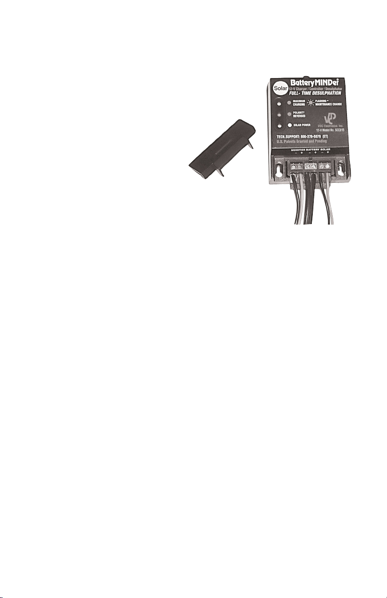
Solar Controller Must be mounted in an area where it can be easily seen,
protected from the elements (direct rainfall), and bright sunlight (where
it would be difficult to see the 3 LED status indicators). Do not attempt
to extend or replace (substitute) the quick connect-disconnect battery
cables supplied with your system, as it is important the controller be in the
same general temperature environment as the battery(s). Use the already
attached Velcro adhesive pad to either temporally or permanently mount
the controller. This will allow you to change its location, should you ever
Rev. B-062811 - 2 - P/N VDC SCC005-015-MNL
BatteryMINDer® SCC005 & 015
wish to, without leaving holes behind. You may also choose to use the
screw holes provided.
Connect output wires from solar panel to solar controller by sliding terminal
cover on controller to expose terminals beneath. Be careful to observe
correct polarity. Do one wire at a time. Do not have solar panel exposed
to sunlight. Do not touch wires together.
Connect cord set (supplied) to battery clamps or directly to terminals
(depends on battery type) Observe polarity indications on ring end of
wires: RED = + (positive) BLACK/BLUE = - (negative).
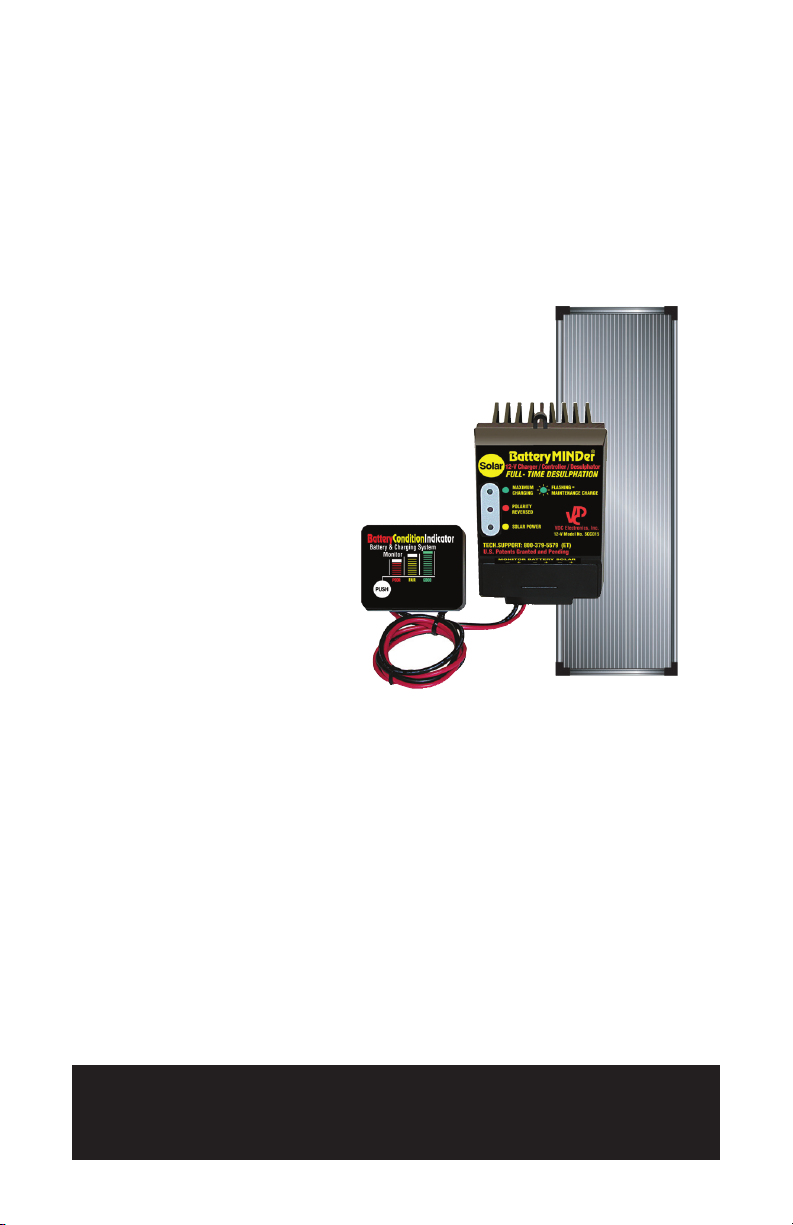
Solar Controller has three (3) separate LED status indicators: They are:
YELLOW = Solar Power - Lit when sufficient sunlight is available to
•
charge/maintain/desulfate battery(s)
RED = Polarity Reversed (Battery only) If lit RED, reverse battery
•
connector wires to battery.
GREEN = Battery Charge If lit (solid) battery is being charged-
•
desulfated. If it blinks (flashes) battery is being maintained and
desulfated (if required).
IF NO LEDs ARE LIT, SOLAR OUTPUT IS NOT SUFFICIENT TO ALLOW
ANY FUNCTIONS TO OCCUR. YOU MUST WAIT FOR ADDITIONAL
SOLAR OUTPUT TO OCCUR, BEFORE ANY ACTION CAN TAKE
PLACE.
Note: Never try to use your SCC005/SCC015 solar controller with any
other solar panels in excess of 15 watts total. Doing so will burn our
your unit and void your 5-year Warranty and 1-year Guarantee.
MOUNTING INSTRUCTIONS
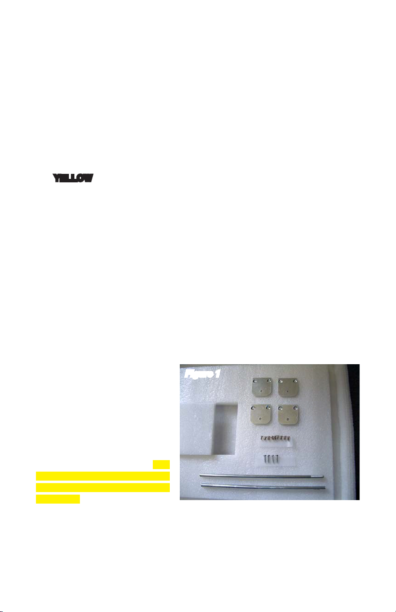
Figure 1
Kit with Temporary and
Permanent Mounting Brackets.
See Figure 1.
The panel comes with two
arms for angling the panel for a
temporary installation and four
brackets for installing the panel
permanently on a surface. The
brackets and screws are in the
cut-out in the foam underneath
the panel.
Mount the panel with the black
side up and silver side down. It must be placed in a location where there
is maximum sunlight.
Try to locate an area where you do not have to extend the cord. If this is
not possible, the cord may be extended by an additional 5 feet.
Rev. B-062811 - 3 - P/N VDC SCC005-015-MNL

BatteryMINDer® SCC005 & 015
Temporary Installation with
Arms
Figure 2
See Figure 2.
Use the arms to angle the
panel for optimal sun exposure.
The panel has two nuts in the
groove at each short end of
the panel. You may place the
panel temporarily, for example,
on the ground or on top of the
vehicle.
Screw the arms provided
1.
in the kit in the nuts that
are in the groove at each short end of the panel.
Let the panel rest on a flat surface.
2.
Make sure that you place the panel in a location where it is not going
3.
to fall down and where you are going to get maximum sunlight.
Permanent Installation with Brackets
See Figure 3.
Use the brackets provided in the kit to install the panel permanently to a
surface. You could attach the panel, for example, to a wall, on the roof,
etc. Leave about 1” between the surface and the panel for airflow. The
manufacturer is not responsible for any damage to the panel caused by
incorrect installation.
Unscrew the flat head
1.
screws from the brackets
Figure 3
in the groove at both ends
of the long side of the
panel.
Use the Phillips head
2.
machine screws provided
in the kit to screw each
bracket on the panel.
Use the Phillips head sheet
3.
metal screws provided in
the kit to attach the panel
to the surface. If you need
longer screws, buy them
from the hardware store.
Leave about 1” between the surface and the panel for airflow. Insert,
4.
for example, piece of wood between the bracket and the surface to
create the space.
Make sure that you install the panel securely. The manufacturer is
5.
not responsible for any damage to the panel caused by incorrect
installation.
Rev. B-062811 - 4 - P/N VDC SCC005-015-MNL

BatteryMINDer® SCC005 & 015
BATTERY CONDITION INDICATOR (BCI):
Your BCI will give you a quick and accurate indication of your battery(s)
state of charge-condition. By properly using
your BCI you can determine whether your
battery needs to be charged, is not holding
its charge or needs to be desulfated. This
is what you must do if you expect accuratehelpful results: ALWAYS test your battery
only after it has been charged as fully as
possible with a high power charger (5 -10
Amp rated) and left “rested” for 10 to 24
hours*. If you don’t follow these directives
you will obtain information that is inaccurate
or down right misleading. Take your time
and do it right and your battery(s) will reap the benefits and so will your
pocketbook.
* “Rested” means a charged battery that has not been recharged or
discharged for a minimum of 10 hours and has had no load attached to it
during this time period.
BCI INSTALLATION:
Turn engine and ALL accessories off. Carefully think of the best location
on or near your battery to locate your BCI so it can be easily seen and
read. Clean surface you plan to attach BCI to using an alcohol cleaning
pad.
Attach the ring terminal on the RED wire of your BCI to the (+) Positive
clamp on your battery. Attach the ring terminal on the BLACK wire of your
BCI to the (-) Negative clamp on your battery.
TESTING BATTERY:
(Engine and ALL loads must be off for accurate readings) Remember,
only test a fully charged battery and only after it has “rested”* for 10 hours
minimum.
Press the area on the face of your BCI in raised area marked PUSH.
If all three (3) LEDs light (RED, YELLOW and GREEN) your battery is
“good” = fully charged = 12.5 – 13.2 volts.
If only the RED and YELLOW LEDs light your battery is “fair” = 12.0 – 12.5
volts.
If only the RED LED lights your battery is in “poor” condition (11.5 – 12.0
volts). Battery needs to be desulfated fully before it can be further evaluated
to determine if it can be returned to “good” condition. WHEN NO LEDs are
lit, battery can be considered “DEAD”, unlikely able to be restored. AGAIN,
this can only be accurately determined if you have correctly allowed your
Rev. B-062811 - 5 - P/N VDC SCC005-015-MNL

BatteryMINDer® SCC005 & 015
battery to “rest”* after first having fully charged it as indicated above.
IMPORTANT NOTE: Fused lead (located on positive lead of battery
connector): ATC-3 blade type 3 amp rated. DO NOT ATTEMPT TO
BYPASS OR REPLACE WITH HIGHER RATED FUSE; SERIOUS
DAMAGE WILL OCCUR.
FREQUENTLY ASKED QUESTIONS:
Q: Can the Solar BatteryMINDer be used to charge, maintain and
desulfate any size or type lead acid 12-volt battery such as sealed gel,
AGM, deep cycle, marine, maintenance free electrolyte?
A: YES, BatteryMINDer can charge, maintain and desulfate any type size
lead acid based battery, regardless of construction or brand. It is however
limited in power (charge current output) by the solar panel (15 watts = 15v @ 1.0 amps). If possible, always charge your battery(s) to full capacity
using a plug-in type 120 Vac input high output charger, before connecting
it to your solar maintenance charger.
Q: Can BatteryMINDer be used to maintain and desulfate more than one
battery at a time?
A: YES, but remember the limitation of the solar panel will determine
how much current output your Solar BatteryMINDer can supply to the
battery. Normally, 2 parallel connected medium sized (auto size) batteries
can be maintained, if they are in good condition. See our definition of a
“good” battery in instructions for the Battery MINDer SCC005/015 solar
maintenance charger-desulfator.
Q: Why do the solar LED indicators turn off and then suddenly turn on
seconds later?
A: When the sun goes behind a cloud the solar controller shuts down,
in order to prevent the battery from being discharged due to low or no
solar energy. As soon as sufficient solar energy is detected by the solar
controller, the LED indicators turn on again and unit resumes its function
as a charger-maintainer-desulfator.
Q: Why doesn’t the GREEN LED start blinking immediately after low
solar shut off, when just before the LEDs turned off the GREEN LED was
blinking?
A: For the GREEN charge power LED to blink unit must first charge
battery to approximately 14.2-volts. Once it reaches this voltage the unit
automatically switches to a lower float-maintenance level where it holds
the battery’s voltage at approximately 13.4-volts. For the GREEN LED
to start blinking the unit must first charge the battery again to the 14-volt
level. This can take from several minutes to several hours, depending on
battery size and the amount of solar energy hitting the solar panel
Rev. B-062811 - 6 - P/N VDC SCC005-015-MNL

BatteryMINDer® SCC005 & 015
FOR REPAIR OR REPLACEMENT
All returns must be authorized by VDC Electronics.
In the event that you believe your product may be defective, you MUST
speak to a VDC Electronics technician at 1-800-379-5579 x206 (ET)
before proceeding further.
NOTES
MODEL BatteryMINDer SCC0
SERIAL NUMBER _____________________________
PLACE OF PURCHASE _____________________________
DATE OF PURCHASE _____________________________
Rev. B-062811 - 7 - P/N VDC SCC005-015-MNL

BatteryMINDer® SCC005 & 015
ALL returns must be authorized by VDC Electronics
after speaking to a VDC Electronics technician at 800379-5579 x206 (ET). Please see our “Repair or Replacement”
section of this manual for additional information.
BatteryMINDer One-Year 100% Unconditional
Money-Back Guarantee
This BatteryMINDer product is guaranteed to perform as claimed or
WE will refund your full purchase price, including all taxes, shipping or
handling cost applicable to the purchase.
Unit must be returned freight prepaid together with Proof of Purchase
directly to VDC Electronics, Inc., NOT TO THE DEALER FROM WHICH
IT WAS PURCHASED.
BatteryMINDer Five-Year Limited Warranty
VDC Electronics, Inc. warrants this product for FIVE years from date
of purchase at retail against defective material or workmanship and
will be repaired or replaced at no charge. We make no warranty other
than this limited warranty and expressly exclude any implied warranty
including any warranty for consequential damages. This limited
warranty is not transferable.
Unit must be returned freight prepaid together with Proof of Purchase
directly to VDC Electronics, Inc., NOT TO THE DEALER FROM WHICH
IT WAS PURCHASED.
IMPORTANT NOTICE
BatteryMINDer® Five-Year Warranty Registration Reminder
Online Registration:
http://www.batteryminders.com/register
Please register your unit online within 10 days of purchase. Due to
the ever-changing technology associated with this BatteryMINDer®
unit, we may be unable to keep you apprised of significant upgrades,
changes, etc. without your registration. The information you provide
upon registration will be used to keep a record of your purchase and
will assist in providing support should you ever need to contact our
Technical Service department:
techsupport@vdcelectronics.com; 800-379-5579 x206 (ET).
Rev. B-062811 - 8 - P/N VDC SCC005-015-MNL
 Loading...