

Page 1
6331G2
031-061
852-2225
852-0005
BM-AIK2A
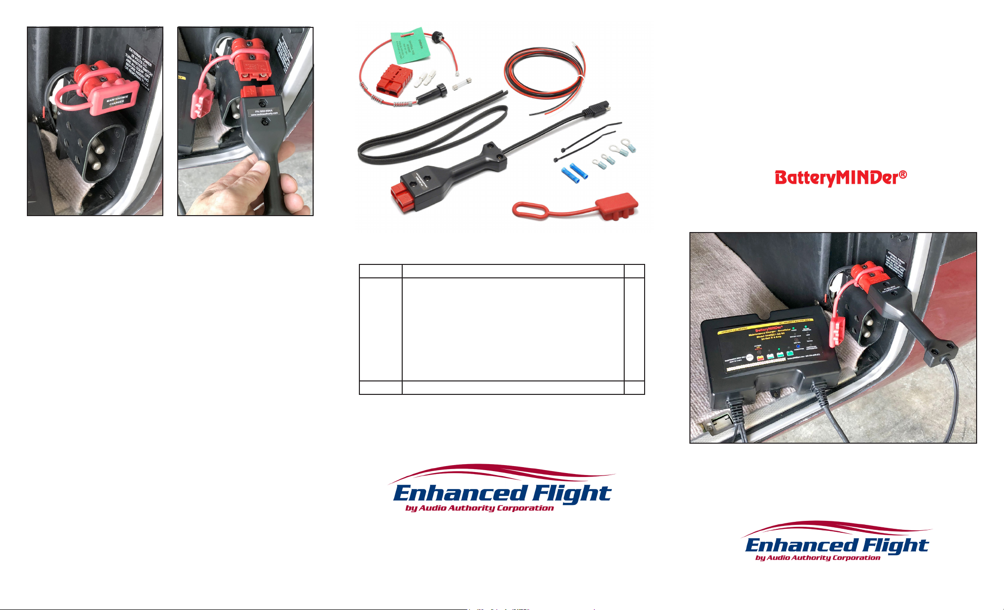
Figure 5. Finished installation example.
7. Crimp the appropriate terminals to harness leads and attach to the battery
relay terminals, red wire to the positive terminal and black to negative or
ground. If required, use alternate approved terminal hardware.
8. Placard the SB50 plug/cover using the supplied label or equivalent.
9. Verify continuity and proper polarity to battery.
10. Connect the SAE-to-SB50 adapter harness to the BatteryMINDer’s output
cable.
11. Connect the BatteryMINDer SB50 output to the airframe SB50 and test for
proper operation.
12. Make appropriate entry in airframe maintenance logbook to document
installation and return aircraft to service. Sample text below, edit as required
for specic installation:
908-059
882-014
910-111
910-110
802-694A
910-035
716-367
Parts List – PN: BM-AIK2A
Weight of all installed items is negligible. The 802-694A is not installed on the aircraft.
Part # Description Qty
6331G2
716-367
761-451
852-2225
852-0005
882-014
908-059
031-061
910-111
910-110
910-035
802-694A SAE to SB50 adapter harness (connects to charger not aircraft) 1
Anderson SB50 polarized plug (red) w/solder contacts
Elastomeric insulating dust cover for SB50
Cover Label “BATTERY MAINTENANCE CHARGER ONLY”
MIL-W-22759/16 16-gauge unshielded wire, red (250°C)
MIL-W-22759/16 16-gauge unshielded wire, black (250°C)
MIL-I-3190E silicone-coated berglass sleeve
Fuse-holder, phenolic in-line bayonet w/15” wire loop (125°C)
Fuse, 15-amp 3AG style glass cartridge, 32VAC/VDC
Terminal, 5/16” ring, 14-16 AWG insulated (MS25036-109)
Terminal, #10 ring, 14-16 AWG insulated (MS25036-108)
Butt splice 14-16 AWG insulated, crimp
1
1
1
6’
6’
3’
1
1
2
2
2
Installation Instructions
Airframe Interface Kit for
Maintenance Charger-Desulfator
“Fabricated & installed 2-wire battery charger connection harness using
MIL-W-22759/16 wire with 15A inline circuit protection fuse. Attached to battery
relay and airframe ground with ring terminals. Terminated opposite end with
Anderson SB50 plug with protective cover and mounted in forward baggage
compartment. All work IAW AC43.13/1B. Veried continuity, polarity, tested with
charger and for proper aircraft electrical system operation. No defects noted at
this time.”
2048 Mercer Road, Lexington, KY 40511-1071 USA
800-322-8346 • 859-233-4599 • Fax: 859-233-4510
[email protected] • www.audioauthority.com/aviation
752-647D 20190205
Page 2
Background and Regulatory Information
Read Completely Before Beginning Installation
Some non-aviation BatteryMINDer models are supplied with an automotivegrade battery connection harness and a battery-mounted temperature sensor.
However, these are not eligible for installation on FAA-certied aircraft, under
Federal Aviation Regulations 14 CFR §21.9. They are suitable only for temporary
connection or bench charging but cannot be legally installed on the aircraft.
Aviation-specic BatteryMINDer models are supplied with a battery clip harness
for temporary connections for a battery that is removed from the airframe.
This kit provides standard aircraft parts acceptable under 14 CFR §21.9 for an
FAA certicated mechanic to fabricate and install a fused, 2-wire harness to
access a certied aircraft’s lead-acid storage battery or related battery electrical
bus, for the purpose of connecting an aviation-specic BatteryMINDer brand
of low-current (8A or less), continuous-duty, maintenance-type battery charger.
The nished harness typically has ring terminals at the battery relay & ground,
connecting to an Anderson SB50 polarized plug at the opposite end via MIL-spec
unshielded 16-gauge aircraft wire, with a 15-amp in-line protective fuse. An
insulating dust cover protects the plug when not connected to the charger. This
product is not designed or intended for chargers greater than 8-amperes.
Installation Procedures
1. Determine best electrical access to the aircraft battery. See installation
examples in a variety of airframes at www.audioauthority.com/BM-AIK2A.
Since batteries are regularly removed for inspection, maintenance and
replacement, we recommend attaching the positive ring terminal to the
battery relay post or stud that is connected to the positive battery cable
and the negative to a convenient airframe ground (see Figure 1). Plastic
or composite airframes that do not have battery busses may require direct
connection to battery terminals. The best method to access the battery varies
by aircraft type and must be determined by the installing mechanic.
2. Determine a safe location to secure the red SB50 plug where it can be
readily accessed for connecting the charger. Keep the distance from the
plug to the battery as short as possible. If wire length required is longer
than 6’ supplied in this kit, do not splice. Run a continuous length of wire as
required.
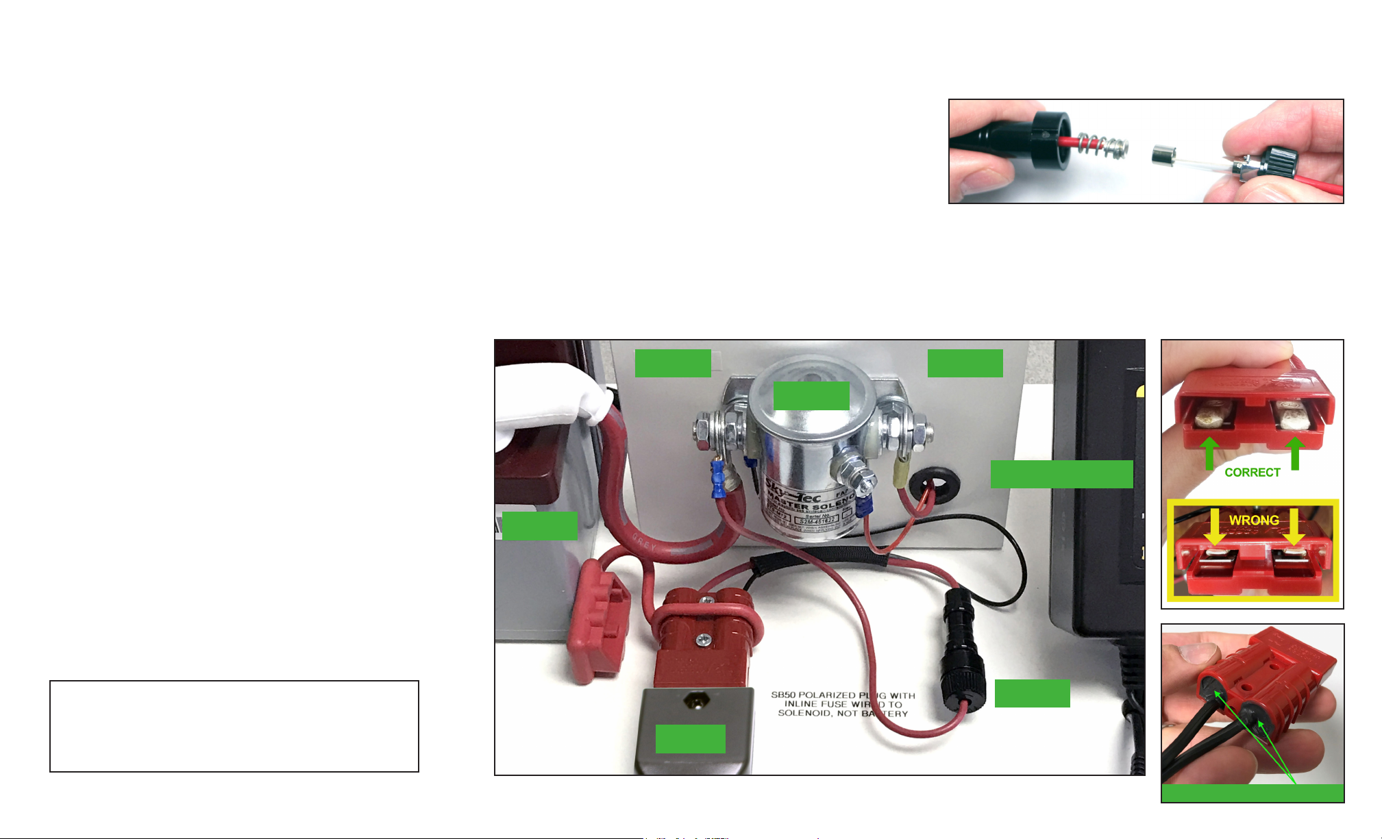
3. Assemble SB50 plug to wiring. Take care to observe proper orientation
when inserting the contacts into the enclosure (Figure 2). Fill the plug’s wire
cavities with RTV for strain relief and allow it to set (Figure 3).
4. Route and secure the wiring harness and trim to length. Use protective
sleeve as necessary to prevent chang against airframe or other
components.
Figure 4
HOLDER SPRING
5. Assemble the fuse holder:
a) Cut wire leads, remove springs (use smallest spring – discard others).
b) Assemble fuse and holder as shown in Figure 4.
c) Install cap to provide positive contact pressure with the fuse.
6. Position the assembled fuse holder so it is accessible and close to the
battery relay or unswitched battery bus.
FUSE
CAP
This kit can be installed as a minor alteration under 14 CFR §1.1 and §21.93(a)
as it has “no appreciable effect on the weight, balance, structural strength,
reliability, operational characteristics, or other characteristics affecting the
airworthiness” of the aircraft. No Form 337 submittal or FSDO eld approval
is required per FAA Order 8900.1 Figure 4-67. A §43.9 airframe maintenance
logbook entry is required and sufcient for return to service.
These instructions are advisory only. Aircraft models and congurations vary
widely, so an airworthy installation depends on the judgment of a competent
mechanic to determine the best option. This kit provides commonly used
installation parts. Some airframe congurations may require different parts that
are not supplied. Similarly, a length of protective berglass MIL-spec sleeve is
provided to protect the harness from airframe chang, as needed in the judgment
of the installing mechanic. Other protective and security measures not included in
this kit may be needed and employed at the discretion of the installing mechanic,
who is ultimately responsible for the airworthiness of the installation.
This kit also includes an adapter harness to convert the charger’s SAE (trailer
plug) output connector to a mating Anderson SB50 plug. This harness is
connected to and remains with the charger; it is not installed on the aircraft.
Finally, temperature sensing for aviation BatteryMINDers is accomplished by use
of VDC’s Ambient Temperature Sensor (ATS-1), a small plug connected to the
short pigtail on the charger, not installed on the battery or airframe.
IMPORTANT: This harness is designed only for maintenance battery
charging, not for supplying ground power for airframe operations.
Disconnect the charger before turning on airframe electrical power.
Reconnect the charger after turning airframe electrical power off to
recharge and then maintain/disulfate the battery.
Figure 2
BATTERY IN OUTPUT
SOLENOID
BatteryMINDer
CHARGER-DESULFATOR
BATTERY
Figure 3
FUSE
CHARGER
HARNESS
Figure 1. Simplied example of connection to battery solenoid. For more examples, see www.audioauthority.com/BM-AIK2A.
FILL WITH RTV SILICONE
 Loading...