


BatteryMINDer
®
Model 28252-AA-Series
(With Desulfation)
INSTRUCTION MANUAL
28-Volt @ 25 Amp
Avionic Power Supply / Charger -
Desulfator
FOR 24-V LEAD-ACID AIRCRAFT BATTERY ONLY.
Contact VDC Electronics for any other resets needed
Dip Switch Settings
Standard Aviation
1 8
432
765
Gill 7000 Series, Odyssey & Hawker
1 8
432
765
Huntington, NY 11743 U.S.A.
techsupport@vdcelectronics.com
1 8
VDC Electronics, Inc.
147D Woodbury Road
www.BatteryMINDers.com
Outside of US & Canada,
see page 35 for contact
information
READ AND SAVE THESE
INSTRUCTIONS
See Page 12 for Simplified Operating Instructions
Concorde Aviation
432
765
Rev. I-100511 P/N VDC28252-AA-Series-MNL

BatteryMINDer
®
Model 28252-AA-Series
TABLE OF CONTENTS
Cautions and Features 4
Required Safety Instructions 6
Never Charge a Frozen Battery 7
Unit Location 7
DC Connection Precautions 7
A Spark Near the Battery May Cause Battery Explosion 8
Testing a Filler Cap Lead Acid Battery 9
Qualifying Your Battery 9 - 10
Specific Gravity – Capacity 10
Testing a Sealed, AGM, Lead Acid Battery 11
Use a Digital Voltmeter Only 11
Open Circuit No Load Voltage Table 11
Operating Instructions (Simplified) 12
Control and Indicators 13
Battery Connectors (Included & Optional) 14
Temp Sensor & A2GPU 15
Dip Switch Instructions 15
Operating Instructions (Detailed) 16 - 18
Display (LCD) Error Code Table 17
Temperature Sensor ABS-2825 Instructions 19
LED Indicator Functions 20
Effects of Temperature on Battery Life 21
AGM and Flooded Charge & Float Voltages at Various
Temperature Ranges 22
Troubleshooting 23
Detailed Specifications 24
AC Power Input Characteristics 25
Factory Preset Table 26 - 27
Rev. I-100511 Page 2 P/N VDC28252-AA-Series-MNL

BatteryMINDer
®
Model 28252-AA-Series
TABLE OF CONTENTS (con’t.)
Power Supply Mode Selected Table 28
Safety and Protection Table 28
Electrical Cable and Physical Parameters 29
Desulfator Wave 30
Top View and Dimensions 31
LED Aviation Display Table 32
Your Notes 33
Repair or Replacement (US & Canada) 34
Repair or Replacement (Outside US & Canada) 35
Warranty 36
Rev. I-100511 Page 3 P/N VDC28252-AA-Series-MNL

BatteryMINDer
®
Model 28252-AA-Series
CAUTIONS: READ AND FULLY UNDERSTAND BEFORE
OPERATING. Contact VDC Electronics if uncertain about
any settings or operation.
BatteryMINDer® Charger / Power Supply / Desulfator /
V-balancer
Switching mode with Microprocessor-controlled
Input: 100-240Vac / Output: 24Vdc 25Amp
User’s Manual and Important Safety Information
Model: 28252-AA-Series
FEATURES
Congratulations on purchasing VDC Electronic’s new generation
switching mode Battery Charger - Power Supply - HF Pulse-Type
Desulfator.
This BatteryMINDer® comprises both patented technology
and patent pending technology and incorporates the following
features:
High frequency switching mode = reduced weight, size and higher
•
(>85%)
Microprocessor controlled - ensures precise voltage, current and time
•
related functions
Auto universal AC input with Power Factor Correction (PFC) control
•
- no manual switching = error free match to input power source worldwide
High efficiency with low input current allow use of AC extension cable
•
(up to 250’-16AWG)
Aviation specific charging modes - ensures full compliance with major
•
aviation battery manufacturer’s specifications
V-balancing mode provides individual battery voltage balancing (2 x
•
12-V battery connected in series) and battery internal cells balancing
(US Patent Pending). Requires VDC Authorized reset and
additional Temp-Voltage Sensor.
Manual button select power supply output for “no battery drain”
•
when powering avionics-electronics.
Manual button select for high power Desulfation pulse output to
•
prolong battery life- (USA Patented and Patent pending).
LCD meter- display shows charging status and function settings.
•
Rev. I-100511 Page 4 P/N VDC28252-AA-Series-MNL

BatteryMINDer
Displays charging current, voltage, charging time, charging AH,
•
®
Model 28252-AA-Series
output power, battery temperature.
Displays function settings: Power supply, Charge, Maintenance,
•
Desulfation.
Dip switch resets for different transition current and charging voltage
•
levels.
Detachable AC input cord receptacle for IEC world wide safety
•
approved cord sets.
14’ DC output cable with Heavy duty Anderson connector.
•
AC On / Off power switch Plug ‘n Run simplified operation.
•
Dip switch setting for equalization mode.
•
Output short circuit and reverse polarity protection.
•
Internal over-heat protection.
•
Severe battery plate sulfation diagnostics.
•
Battery Charging temperature compensation (At the Battery).
•
Battery thermal run-away protection (DI/Dt).
•
Charging time management for each charging stage.
•
RS232 interface connector provided for data communication with
•
PC (Future Option Date TBD).
Remote LCD display provided-(Future Option date TBD).
•
Designed to UL/cUL, CE, FCC, EMC safety certification standards.
•
* Contact VDC Electronics Tech Support (techsupport@vdcelectronics.com) /
800-379-5579 (ET) for instructions on this subject
Rev. I-100511 Page 5 P/N VDC28252-AA-Series-MNL

BatteryMINDer
®
Model 28252-AA-Series
REQUIRED SAFETY INSTRUCTIONS
WARNING
TO REDUCE THE RISK OF FIRE, ELECTRIC SHOCK, OR INJURY
TOPERSON, OBSERVE THE FOLLOWING:
This unit is designed for protected use and should never be exposed
•
to rain.
Do not attempt to use the unit if it has been dropped or damaged.
•
Never attempt to charge a damaged battery, frozen battery or non-
•
rechargeable battery.
Do not use the unit in a closed area or poorly-ventilated area.
•
Never smoke, use an open flame, or create sparks near a battery
•
or unit during charging operation as this may cause an explosion /
explosive gas.
Do not operate the unit if the cord or plug is damaged.
•
Do not disassemble. VDC Electronics MUST be contacted for repair,
•
replacement or analysis. Keep away from infants, children and pets.
Switch off or remove AC power before connecting or disconnecting
•
to battery.
Refer to the battery Manufacturer’s specific recommended values
•
to determine if standard unit settings are correct. Contact VDC
Electronics Tech Support before making any changes
Check Battery Manufacturer’s specific precautions - such as removing
•
or not removing battery from aircraft before charging.
Always remove battery from aircraft before equalizing or desulfating.
•
Someone should be within range of your voice or close enough to
•
come to your aid if working near a lead-acid battery.
Wear protective goggles and turn your face away when connecting or
•
disconnecting a battery.
If battery acid contacts your skin or clothing, wash immediately with
•
soap and water. If acid enters your eye, immediately flush the eye
with running cold water for at least 10 minutes and seek medical
attention immediately.
To reduce risk of damaging the Battery, avoid dropping any metal
•
tools onto the battery.
Never rest the Battery being charged on top of your Battery
•
Charger.
The Battery Charger / power supply should be kept as far away from
•
the Battery as the output cables permit.
When using the Temperature Sensor at any location other then on a
•
battery the ring terminal must be insulated.
Rev. I-100511 Page 6 P/N VDC28252-AA-Series-MNL

BatteryMINDer
®
Model 28252-AA-Series
Always follow battery manufacturer’s strict
instructions for proper care, charging and testing of
battery. Always use their FAA Approved “Instructions
for Continued Airworthiness” (ICA). Questions
relating to the subject should be referred directly
to the battery manufacturer to be certain of current
requirements that may have been added to or changed
since publication of their instructions.
NEVER CHARGE A FROZEN BATTERY OR ONE AT A
TEMPERATURE ABOVE 123° F.
PREPARING TO CHARGE
Always remove ground wire first.
a.
Be sure area around battery is well ventilated while battery is
b.
being charged. Force gas vapors away by using a fan.
Clean battery terminals. Be careful to keep corrosion from
c.
contacting eyes.
Study all battery manufacturer’s specific instructions such as
d.
recommended charge rates.
Determine condition of battery, by referring to instructions
e.
herein, before ever attempting to charge or desulfate any /
all batteries.
Make sure unit is as far away from battery as output cables
f.
permit.
Never place unit directly above battery being charged; gases
g.
from battery will corrode and damage unit.
Do not operate unit in a closed-in area or restrict ventilation
h.
in any way.
Do not set battery on top of unit.
i.
DC CONNECTION PRECAUTIONS
Note: Steps to be done in a well-ventilated area.
a. Connect and disconnect DC output clips from battery only
after removing unit power cord from outlet.
b. Attach clips to battery posts and twist or rock back and forth
several times to make good contact. This tends to keep clips
from slipping off terminals and reduces risk of sparking.
Rev. I-100511 Page 7 P/N VDC28252-AA-Series-MNL

BatteryMINDer
®
Model 28252-AA-Series
UNIT LOCATION
A SPARK NEAR THE BATTERY MAY CAUSE BATTERY
EXPLOSION. TO REDUCE RISK OF A SPARK NEAR
BATTERY:
a. Connect (RED) charger clip to (POS+) post of battery.
b. Position yourself and free end of cable as far away from
battery as possible, then connect NEGATIVE (BLACK) charger
clip to free end of cable.
c. Do not face battery when making final connections.
d. When disconnecting unit, always do so in reverse sequence
of connecting procedure and break first connection while as far
away from battery as practical. Do not attempt to permanently
install unit not specifically designed-approved for permanent
installation, especially in a wet high moisture environment.
Rev. I-100511 Page 8 P/N VDC28252-AA-Series-MNL

BatteryMINDer
®
Model 28252-AA-Series
QUALIFYING YOUR BATTERY:
Preliminary Requirements
NOTE: The BatteryMINDer has no electrical output unless it is
connected to a healthy battery. Testing the BatteryMINDer with
a volt or an Amp meter without the unit being connected across a
good battery will result in a false reading. If you experience any
problems, or are not sure of how to properly use or connect your
BatteryMINDer, please e-mail our Tech Support Dept. at:
techsupport@vdcelectronics.com or call our toll-free technical
support line 800-379-5579 x206 (Eastern Time) (USA & Canada
ONLY). Be certain to leave your phone number with the area
code, time zone and the best time to call.
To gain the best result from your unit and to maximize the life and
performance of your batteries we strongly recommend you qualify
(test) your batteries before attempting to either charge-maintain
or desulfate them. Remember, even if you just purchased a
“new” battery it may have been subjected to conditions that
have caused “sulfation” such as an extended period at high
temperature (>=80°F).
NOTE: If your battery is new and you are certain it was
not subject to conditions that could have caused sulfation*,
even before you purchased it, then you can disregard our
recommendations for qualifying / testing your battery, before
using the BatteryMINDer.
* Such as high temperature storage (=/> 80°F) and/or allowed to
self-discharge to 24.8 Volts or lower.
Testing a Filler Cap Lead Acid Battery
1. Carefully remove all filler caps from your battery.
2. Check the water-liquid electrolyte level. If the level is low or
has ever been below top of plates, severe lead plate sulfation
has taken place. Significant recharge/reconditioning time is
needed to restore these plates to a condition where the battery
can be expected to function normally.
3. Refill each cell with distilled water only to the liquid level
indicator found in each cell. Before proceeding further you must
Rev. I-100511 Page 9 P/N VDC28252-AA-Series-MNL
BatteryMINDer
®
Model 28252-AA-Series
be thoroughly familiar with the safety and operating instructions.
4. Recharge the battery with the BatteryMINDer to ensure that
it is slowly and completely charged before you determine its
condition. Allow battery to “rest”* overnight or momentarily apply
a small load to remove the “surface” charge which creates false
voltage readings.
* “RESTED” = a battery that has been as fully charged as possible and left
disconnected from charger or any type load overnight. Apply a small load to
remove surface charge effect.
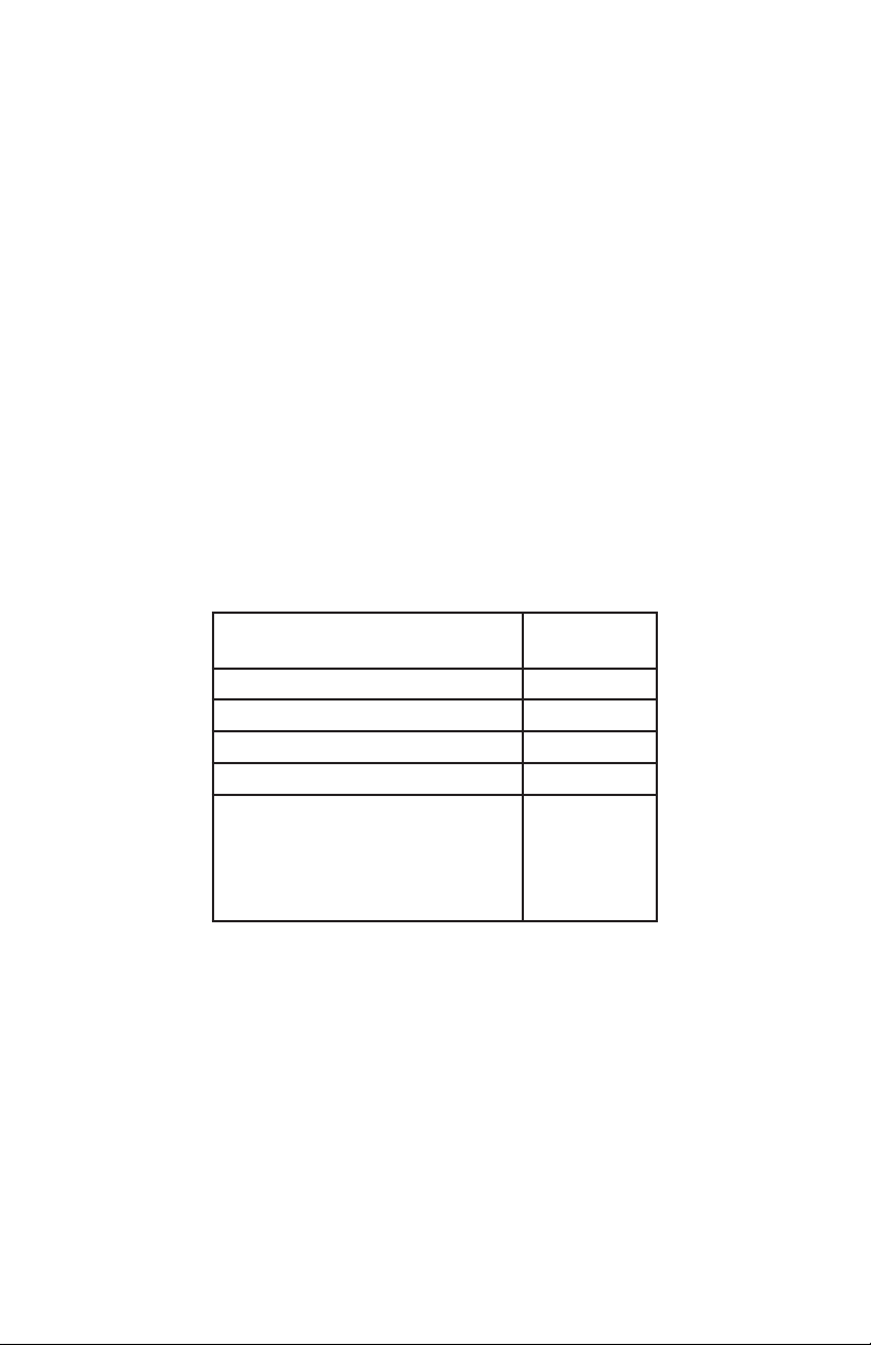
Specific Gravity – Capacity
Temp. Compensated Hydrometer
- meter or 4 ball type
1.285 100%
1.245 75%
1.210 50%
1.175
1.140
May denote shorted cell or battery
that has been severely discharged
and may not be recoverable
Full Capacity
Percentage
25%
0%
TABLE 1
Rev. I-100511 Page 10 P/N VDC28252-AA-Series-MNL

BatteryMINDer
®
Model 28252-AA-Series
TESTING A SEALED, AGM
LEAD ACID BATTERY
These batteries have no filler caps or manifold-type covers. Because you
cannot gain access to the interior of your battery you cannot test it with a
hydrometer.
USE A DIGITAL VOLTMETER ONLY:
1. Recharge the battery with the BatteryMINDer to ensure it is as
completely charged as possible, before you determine its condition. Allow
battery to “rest” (see pg. 9) overnight before testing with a digital voltmeter
only.
Failure to test a “rested” (see pg. 9) battery will cause false readings. Be
certain to read and understand all safety related instructions (pages 3 to
7) before proceeding further.
2. Measure battery’s voltage, without any load attached. If the voltage
is less than 25.2 volts (Typically 75% of charge) the battery may be too
heavily sulfated to be fully recoverable. If voltage is 25.2-V or higher
recovery can be expected, given sufficient time.
3. Press desulfation button to start process of dissolving sulfate crystals.
Ensure battery is removed from aircraft prior to desulfation. Continue
in this mode for 72 hours. Stop process by pressing desulfation button.
Test battery voltage and compare to table 2 below. If voltage is not in the
full capacity range restart the desulfation process and continue for an
additional 72 hours before retesting. Continue repeating this procedure
until no further increase in battery voltage is observed.
Note: Do not expect to completely dissolve sulfate in a day. Long
established sulfate will require a longer period to be fully dissolved. Be
patient and you will be rewarded with a “sulfate-free” battery. If not
seriously damaged by sulfate, battery has a very good chance of meeting
80% Cap (Airworthy) Test.
OCV - “Rested”
Voltage
OCV=Open Circuit
No Load Voltage
TABLE 2
Rev. I-100511 Page 11 P/N VDC28252-AA-Series-MNL
25.8 - 26.2 Volts 100%
25.2 - 25.8 Volts 75%
24.8 - 25.2 Volts 50%
24.4 - 24.8 Volts 25%
24.0 - 24.4 Volts 0%
<22 Volts
= shorted
Full Capacity
Percentage

BatteryMINDer
®
Model 28252-AA-Series
Simplified Operating Instructions
The BatteryMINDer has no electrical output unless it is connected to a
battery with a minimum of 6-Volts or when in Power Supply Mode.
• Attach Temperature/Voltage Sensor to TempSensor Receptacle A
and Ring Terminal to positive Battery Terminal.
• Attach Battery Connector Attachments (BCA) to DC-CORD Output of
unit.
• Plug AC Power Cord into 95 - 240 Vac electrical outlet. Turn AC
POWER Switch On. Unit will automatically start in Charge Mode
(expect up to a 10 second delay).
• Observe ERROR LED indicator. If lit RED, and LCD displays error
code (E01), shut power off and reverse battery connector attachments
on battery.
• Always power-off unit before disconnecting from battery(s).
NOTES:
If ambient temperatures are ≥80°F or ≤60°F, you MUST ALWAYS use
•
Temperature/Voltage Sensor (on positive terminal of battery) to prevent
improper charging.
Unit automatically starts in charging mode.
•
Hold Power Supply button 5 seconds to operate as a power supply.
•
Press Desulfation button to operate desulfation mode. Ensure battery is
•
removed from aircraft prior to desulfation.
To Change the Mode on the Batteryminder 28252-AA-Series:
After the unit is powered on, if you do not press a Mode Button within 30
•
seconds, you will need to press the Mode Button TWICE.
If the unit has not had a Mode changed within 30 seconds, you will need
•
to press the Mode Button TWICE
In each instance, you only need to press the Mode Button ONCE if done
within 30 seconds after the previous operation.
See additional information on this function on Page 19.
IF IN DOUBT REGARDING ANY OF THE ABOVE, REFER TO FULL
INSTRUCTIONS
Rev. I-100511 Page 12 P/N VDC28252-AA-Series-MNL

BatteryMINDer
PWR SUPPLY CHARGE DESULFATION
NORMAL AVIATION V-BALANCING
VA
°C%
KW
AH
POWER
(GREEN)
ERROR
(RED)
DESULFATION
(BLUE)
CURRENT OUTPUT
VOLT OUTPUT
TIME ELAPSED
DESULFATION
(Press to Start)
DESULFATION
(Press to Start)
®
Model 28252-AA-Series
Rev. I-100511 Page 13 P/N VDC28252-AA-Series-MNL
AVIATION

BatteryMINDer
BC 2410
Battery Clips
(included)
®
Model 28252-AA-Series
Included & Optional
Battery Connectors
A2RT
11/32” Ring Terminals
(optional)
A2GPU-1
Anderson SB-50 to
Cessna style GPU Plug (optional)
ABS-2825
Temperature/Voltage
Sensor
(At-the-Battery
Sensor)
(included)
*Must be used on aircraft where a relay needs to be activated in order to connect the
battery and GPU.
Rev. I-100511 Page 14 P/N VDC28252-AA-Series-MNL
A2ELCON
ELCON Type
Connector
(optional)

BatteryMINDer
®
Model 28252-AA-Series
When using the Temperature Sensor at any location (other then
on a battery) the ring terminal must be insulated, heat shrink
tubing is recommended. If using the A2GPU-1 or A2GPU2 and are unable to place the Temperature Sensor on a battery
terminal, it may be inserted into the unused cavity of the A2GPU
plug and secured with cable clamp.
A2GPU-1 Plug Instructions
Connect A2GPU
1.
Turn on 28252
2.
Hold down “Power Supply/Charge” for 5 seconds and release
3.
Quickly press “Power Supply/Charge” twice to start charging cycle
4.
Dip Switch Instructions
Disconnect unit from Battery and AC power.
1.
Remove Dip Switch access panel using provided Triangle Bit.
2.
Set switches for desired battery brand setting as shown.
3.
Replace access panel.
4.
Dip Switch Settings
Standard Aviation
1 8
432
765
Gill 7000 Series, Odyssey & Hawker
1 8
432
765
Concorde Aviation
1 8
432
765
Important!
If you require changes to dip switch factory settings, be aware
such changes may negatively affect other battery types if not
reset according to our directions. This may cause harmful levels
of overcharge leading to “out-gassing” of the electrolyte.
Triangle Bit
If battery is in an enclosed-confined area, harmful and corrosive
hydrogen gas will be generated. In addition, dip switches are not
built to be changed frequently and should be very carefully “switched
only when needed”. Any damage occurring is NOT covered by our
warranty or guarantee.
Questions? Call our Tech Support, at (800) 379-5579 ext 206 (ET).
Rev. I-100511 Page 15 P/N VDC28252-AA-Series-MNL

BatteryMINDer
®
Model 28252-AA-Series
OPERATING INSTRUCTIONS
1. Pre-Charge Check
(a) Check the Battery Electrolyte level (Non-sealed Batteries).
If necessary, remove the vent caps and add distilled water so
levels are halfway between the upper and lower fill lines.
(b) Location – Ensure the Battery is in a well ventilated area.
Keep the Unit as far away from Battery as the cables permit.
Never place the unit directly above the battery being charged as
gasses from the Battery will corrode and damage the unit. Also,
keep the unit away from high corrosion / wet and moist areas.
2. Connecting BatteryMINDer to your Battery
(Temp/Volt Sensor A) is used to detect the battery voltage and
temperature and to avoid undercharging and overcharging.
Rev. I-100511 Page 16 P/N VDC28252-AA-Series-MNL

BatteryMINDer
®
Model 28252-AA-Series
3. Aviation charge mode connection
(1). Connect to 24V Aviation battery.
(2). You MUST connect Temperature/Voltage Sensor ABS-2825
(no substitute) to the Positive (+) battery terminal.
(3). Connect the output DC cable RED clips to the battery Positive
polarity (+), the BLACK clips to the battery Negative polarity (-).
4. Connect the unit to AC input power
Turn on the AC power switch.
Note: If the Error Indicator LED is ON and LCD displays E01,
please check your connections as it’s likely that the Positive and
Negative Leads are reversed. Refer to the following Error code
table and Troubleshooting Page for further information.
Display (LCD) Error code table:
Output lead(s) shorted or battery reverse
E01
connected
Soft-Start timed out E02
Bulk charging timed out E03
Battery severely sulfated or damaged E04
Fan faulty E05
Unit shuts down by internal over-
E06
temperature protection
Battery Temp. >131°F/55°C; Resumes
E07
charge at <113°F/45°C
NOTE:
• Unit automatically starts in charging mode.
• Hold Power Supply button 5 seconds to operate
as a power supply.
• Error codes are for Charging Mode only unless
otherwise .
Rev. I-100511 Page 17 P/N VDC28252-AA-Series-MNL

BatteryMINDer
®
Model 28252-AA-Series
5. The Charging Process
The Charging LED’s will indicate the Charging Stages. LCD will display
the values and functional setting.
The charging stages are as follows:
Soft Start: Charges the battery using half the maximum current
•
until the battery voltage is over 22V (indicated by YELLOW Bulk
LED FLASHING). Soft Start occurs if the initial voltage is less than
22V (due to severe-deep discharge)
Bulk Charge: Charges using a constant maximum current until
•
the battery rises to the Absorption level = 85% full (indicated by the
YELLOW Bulk LED ON)
Absorption: This stage charges the battery using a constant
•
voltage providing that the Battery Voltage is over 85% (indicated by
the BLUE Absorption LED ON) .
Equalization: Mode is only activated by calling VDC Electronics
•
Technical Support at (800) 379-5579 x206. Do not use unless
battery is removed from aircraft. Regular use of this mode may
damage battery. Mode ensures full charge to ageing-marginal
batteries and improves performance on capacity tests.
Float / Full: Battery is in Float stage and fully charged, it will be
•
maintained at a safe voltage and ready for use. (The GREEN Float
LED ON - indicates the battery is fully charged).
Desulfation: Mode is activated by pressing “Desulfation” button.
•
Do not use unless battery is removed from aircraft. See Page
11.
6. Disconnecting BatteryMINDer from Battery.
(a) If the Battery is not in end-use installation:
Switch OFF AC power switch, remove the AC Power Socket from
1.
the outlet.
Remove the BLACK lead and then the RED lead, remove the Sensor
2.
A.
Check electrolyte levels if possible (may need topping up with distilled
3.
water after charging)
(b) If Battery is in end-use installation:
Switch OFF AC power switch, remove the AC Power Socket
1.
from the outlet.
Remove leads from battery. Remove Sensor A.
2.
Check electrolyte levels if possible (may need topping up with
3.
distilled water after charging).
Rev. I-100511 Page 18 P/N VDC28252-AA-Series-MNL

BatteryMINDer
®
Model 28252-AA-Series
To Change the Mode on the BatteryMINDer 28252-AA-Series:
• After the unit is powered on, if you do not press a Mode Button
within 30 seconds, you will need to press the Mode Button
TWICE
• If the unit has not had a Mode changed within 30 seconds, you will
need to press the Mode Button TWICE
In each instance, you only need to press the Mode Button ONCE if
done within 30 seconds after the previous operation
This is a safety feature to help prevent inadvertent operations, similar to
an ATM asking you to confirm a transaction. If a Mode Button has not
been pressed within 30 seconds, the button will be locked in the previous
setting. Once you press the button again, the unit will be unlocked. This
“double-press” feature goes into effect after approximately 30 seconds of
not pressing any buttons.
INSTRUCTIONS:
TEMPERATURE SENSOR Type:
ABS-2825 (At-the-Battery Sensor)
MANDATORY WHEN UNIT IS USED WITH Sealed or Maintenancetype Aviation batteries, regardless of construction (AGM, FreeElectrolyte = filler caps)
Do NOT modify by extending or shortening the Sensor cord.
Attaching the temperature sensor to battery:
Connect it to the Positive (+) terminal post (clamp or screw) of the
battery.
Unit is ON
Has Mode been
changed within 30
seconds?
YES
Press Mode
Button ONCE
Rev. I-100511 Page 19 P/N VDC28252-AA-Series-MNL
NO
Press Mode
Button TWICE
ABS-2825

BatteryMINDer
®
Model 28252-AA-Series
LED INDICATOR FUNCTIONS
AC power display LED
AC Power LED On AC power ON
Rev. I-100511 Page 20 P/N VDC28252-AA-Series-MNL
Error LED
RED Error LED ON or Flashing See Troubleshooting section
Desulfation LED
BLUE Desulfation LED Flashing Unit is in Desulfation mode
Charging Status indicated LED
Bulk LED YELLOW Flashing Indicates the battery is at low level and in soft start stage
Bulk LED YELLOW On Indicates the unit is at a maximum charging rate
Absorption LED BLUE On Indicates Battery is over 85% charged
Absorption LED BLUE Flashing Indicates automatic equalization stage is running
Float LED GREEN On Indicates battery is fully charged

BatteryMINDer
®
Model 28252-AA-Series
Temperature has a direct effect on the life of a battery. The design life of the battery is based on an average annual temperature of 25°C (77°F). As the temperature increases above 25°C
(77°F), the life of the battery decreases. The chart below shows
the effects of temperature.
Effects of Temperature on Battery Life*
Maximum Annual Average
Battery Temperature
25°C (77°F) 50°C (122°F) 0%
30°C (86°F) 50°C (122°F) 30%
35°C (95°F) 50°C (122°F) 50%
40°C (104°F) 50°C (122°F) 66%
45°C (113°F) 50°C (122°F) 75%
50°C (122°F) 50°C (122°F) 83%
25°C (77°F) 50°C (122°F) 0%
Maximum Battery
Temperature
Percent Reduction in
Battery Life
For example: If a battery’s design life is 10 years at 25°C (77°F), but the
average battery temperature is 35°C (95°F), the life of the battery will be only
5 years a 50% decrease.
*GNB Industrial Power, A Division of Exide Technologies, Section 92.30 Part No. Z99-Mar/Sep
I&O REV 10/01
Rev. I-100511 Page 21 P/N VDC28252-AA-Series-MNL

BatteryMINDer
AGM and Flooded (wet-cell) Charge and Float Voltages at Various Temperature Ranges**
Temp °F
Optimum Charge
Optimum Float
Temp °C
≥ 120
26.80
24.90
≥49
110 – 120
27.20
25.10
43 – 49
100 -110
27.40
25.30
38 – 43
90 – 100
27.60
25.50
32 – 38
80 – 90
27.80
25.70
27 – 32
70 – 80
28.20
26.10
21 – 27
60 – 70
28.50
26.60
16 - 21
50 – 60
28.80
27.00
10 - 16
40 – 50
29.20
27.40
4 - 10
≤ 40
29.80
27.80
≤4
®
Model 28252-AA-Series
The chart below shows the need to regulate the output voltage of the unit to ensure against over or under charging your
battery over a wide range of temperatures. Using your At-the-Battery Sensor will accomplish this better than any other known
method. Please note: Table is for STANDARD AVIATION setting. The GILL 7000 SERIES, ODYSSEY and HAWKER
setting provides charging voltage of 29.4V and float of 27.2V at 25°C/77°F. The CONCORDE setting provides charging
Rev. I-100511 Page 22 P/N VDC28252-AA-Series-MNL
voltage of 28.2V and float of 27.0V at 25°C/77°F. All settings are properly temperature compensated.

BatteryMINDer
®
Check DC connection between unit and battery and make
sure they are not short-circuiting
Check clips / ring terminals to be sure polarity is correct
Check the Battery condition, age, etc.
If battery cannot be desulfated, it must be replaced
Move battery & Unit to cooler environment
Check the fan on unit
Model 28252-AA-Series
Check charging rate, battery type and condition
Battery cannot be charged and must be replaced
Check Sensor connections
Ring terminal must be firmly fastened to the battery poles
Check for loose battery terminal connections
Check output lead clips. May be loose / damaged
TROUBLE SHOOTING
Output is short circuited
Output polarity connection to
battery is reversed
Battery is severely sulfated
Battery has a damaged cell
Battery aged
protection is activated-on, shutting
down charging functions
Fan faulty
Battery capacity is too large or bat-
tery is in very poor condition
6 hours soft start timer reached
15 hours bulk charge timer reached
12 hours absorption timer reached
Sensor connections are faulty or
loose
Poor connections from Unit to
Battery
Error LED is ON.
LCD displays E01
Problems Indication Possible Causes Suggested Solution
Unit does not work Indicator LEDs are not on No AC power Check AC connections and make sure Power switch is ON
Unit has no DC
output
Rev. I-100511 Page 23 P/N VDC28252-AA-Series-MNL
LCD displays E04
LCD displays E05 or E06 Battery charger internal over heat
No Charging Current Error LED is Flashing and
Stop charging during
charging progress
Fault LED is Flashing
LCD displays E02, E03
or E04
Long charging time,
FLOAT LED does not
come on
Error LED Flash, LCD
LCD displays Normal
meter displays normally
ALL LED’s continuously
or intermittently Flash
charge, but Error LED
continuously Flashes
Abnormal LED
indication

BatteryMINDer
®
Model 28252-AA-Series
DETAILED SPECIFICATIONS (R12) VDC Model No. 28252-AA-Series
24-V 25 Amp H.F. Battery Charger/ Desulfator/ Power supply
Program Code No.: 28252-r0.8
Battery Type: 24V Lead-acid Aviation Sealed or Flooded
Battery
Note: This equipment has been tested and found to comply
with the limits for a Class B digital device, pursuant to
part 15 of the FCC Rules. These limits are designed to
provide reasonable protection against harmful interference in a
residential installation. This equipment generates, uses and can
radiate radio frequency energy and, if not installed and used in
accordance with the instructions, may cause harmful interference
to radio communications. However, there is no guarantee that
interference will not occur in a particular installation. If this
equipment does cause harmful interference to radio or television
reception, which can be determined by turning the equipment off
and on, the user is encouraged to try to correct the interference
by one of more of the following measures:
• Reorient or relocate the receiving antenna.
• Increase the separation between the equipment and
receiver.
• Connect the equipment into an outlet on a circuit different
from that to which the receiver is connected.
Rev. I-100511 Page 24 P/N VDC28252-AA-Series-MNL

BatteryMINDer
®
6.6 ±10% Aac
Model 28252-AA-Series
AC Power Input Characteristics NORMAL TOLERANCE UNIT
Input Voltage 100-240 90-264 Vac
Input Frequency 50/60 47-63 Hz
Unload input current 100 max. mAac
Input Current consumption at 120Vac 60Hz input, output 27V
25A loading
Nominal Efficiency at 120Vac 60Hz input, output 27V 25A >85%
Rev. I-100511 Page 25 P/N VDC28252-AA-Series-MNL
Charging Output Control Characteristics
Charging Flow: Soft Start ChargeBulk ChargeAbsorption ChargeEqualizing Charge (Option)
Float Charge (Full)
Power supply: Desulfation is not automatic (manual)

BatteryMINDer
UNIT
ANCE
TOLER-
®
±1% Vdc
±1% Vdc
Model 28252-AA-Series
±1% Vdc
1
±10% Adc
NORMAL
1
15 ±10% Hours
1
taken)
Aviation charge mode output control:
Factory Presets (defaults)
Soft start charging activity conditions: Battery voltage is between 6-22 ±2% Vdc
Soft start charging output current control: 6.25 ±10% Adc
Soft start mode transits to bulk mode: Battery voltage is above 22 ±2% Vdc
Soft start charging time limit: stops charging 6 ±10% Hours
Bulk charging condition: Battery voltage is above 22 ±2% Vdc
Bulk charging current control: 25 ±10% Adc
Bulk mode transits to Absorption mode: Battery voltage above 28.2
Max. Bulk Charging Time Limit: (Stops charging if
time is exceeded)
Absorption charging activity: Battery voltage above 28.2
Absorption charging output voltage control: Battery voltage is constant at 28.2
Max. Absorption charging time: 12 ±10% Hours
Absorption charging transits to Equal charging conditions:
1) When charging current drops to: 0.5 ±10% Adc
Or 2) Maintain charge until the current acceptance drops by less than 0.10 amp over a 1 hour period
Max Equalizing Voltage: 30 ±10% Vdc
Max Equalizing Voltage: 1 ~ 8 (Subject to Bulk Charge time
Rev. I-100511 Page 26 P/N VDC28252-AA-Series-MNL

BatteryMINDer
®
Model 28252-AA-Series
±1% Vdc
1
NORMAL TOLERANCE UNIT
Aviation charge mode output control:
Factory Presets (defaults)
Max Equalizing Time: 4 ±10% Hours
Rev. I-100511 Page 27 P/N VDC28252-AA-Series-MNL
25.8 ~ 26.1
Float charging output voltage control: Battery voltage is maintained at
Max. Float charging current control 5 ±10% Adc
Restarts Bulk charging when battery voltage is low: Battery voltage is below 25.2 ±2% Vdc
Battery series -50mV/°C ±25% mV/°C
0.5 max. Vdc
Battery temperature compensation activity conditions:
Battery temperature compensation: value for battery
voltage (based on value at 25°C)
Max. unloaded output voltage when disconnected
from battery:
3 max. mAdc
3 max. mAdc
These voltages are for STANDARD AVIATION setting. The GILL 7000 SERIES, ODYSSEY and HAWKER setting absorption voltage is
1
29.4V and float is 27.2V. The CONCORDE setting absorption voltage is 28.2V and float is 27.0V.
Max. output short-circuit current when disconnected
from battery:
Max. ow back current (to unit) when connected to
battery, AC power disconnected
Remarks:
If Temperature - Voltage Sensor connection is faulty, detached or loose, unit will automatically run in Normal charge mode =
NO TEMPERATURE COMPENSATION
Repair or replace before using unit at temperature above 80°F or below 60°F

BatteryMINDer
®
Model 28252-AA-Series
±0.2 Vdc
1
±0.2 Vdc
1
Power Supply (P.S.) mode selected NORMAL TOLERANCE UNIT
Unload output voltage 26.1
Max. current output 25 ±2 Adc
Constant output voltage 26.1
Rev. I-100511 Page 28 P/N VDC28252-AA-Series-MNL
Desulfation mode selected NORMAL TOLERANCE UNIT
Manual desulfation (Press button to start - stop)
Desulfation output pulse peak current control lp-p 20 +10 / -0 Adc
Desulfation output PWM frequency 1000.0 ±10 Hz
Voltage is for STANDARD AVIATION setting. The GILL 7000 SERIES, ODYSSEY and HAWKER setting voltage is 27.2V. The CONCORDE
Desulfation duty 0.10 %
1
setting voltage is 27.0V.
SAFETY & PROTECTION
Safety Standards: UL-1236, EN60335-1. EN60335-2-29
EMC Standards: FCC-Part 15 Class B; EN55014
Input-Output insulation test : 3000Vac 50/60Hz with 1 minutes, 5mAac
Cooling: By Fan forced air - Temperature Sensing
Built-in temperature protected
Output short-circuit, reverse polarity Protection

BatteryMINDer
®
Model 28252-AA-Series
-25°C/77°F to 85°C/185°F
SJT VW-1 105°C 16AWG 3C with 3PIN UL plug, 6
feet external length.
Electrical Cable & Physical Parameters
Input Connector: 250V 15A IEC socket
Rev. I-100511 Page 29 P/N VDC28252-AA-Series-MNL
Input AC switch: ON/OFF power switch
14’ long output cord with Anderson Plugs on both
ends
12” long cord with 50A Anderson Plug and battery
clips
Output Connector: 50A anderson connector
in
Steel Enclosure Dimension: 240 (L) x 215 (W) x 97 (H) mm / 9.45 x 8.46 x 3.8
temperature:
-10°C/14°F to 40°C/104°F Storage
Operating
0 to 90% RH Weight: 3.5 Kg / 7.7 lbs. approx.
Temperature:
Operating
Humidity range:
THDI<=5% (Total Harmonic Distortion of Current)
PowerFactor (PF) =0.98

BatteryMINDer
22.0V 30.0 - 32.0V
Voltage
Current
6.25A
Current limited
Maintenance current
Soft start Bulk
Absorption
Equalizing
Float Time
25A
28.2 - 29.4V
25.8~27.2V
®
Model 28252-AA-Series
*
*
CHARGING CURVE
*
Rev. I-100511 Page 30 P/N VDC28252-AA-Series-MNL
* Depending on model
Remarks: If power fails and then resumes, unit will automatically start from initial charging cycle.

BatteryMINDer
7.0”
177.8 mm
3.5”
88.9 mm
214.9 mm
240.0 mm
9.45”
8.46”
®
Model 28252-AA-Series
BatteryMINDer 28252-AA-Series Top View and dimensions
Rev. I-100511 Page 31 P/N VDC28252-AA-Series-MNL

BatteryMINDer
®
Model 28252-AA-Series
ON OFF OFF OFF OFF OFF
ON FLASH OFF OFF OFF OFF
ON ON OFF OFF OFF OFF
ON OFF ON OFF OFF OFF
ON OFF FLASH OFF OFF OFF
ON OFF OFF ON OFF OFF
ON OFF OFF OFF ON OFF
ON OFF OFF OFF FLASH OFF
ON OFF OFF OFF FLASH OFF
ON OFF OFF OFF FLASH OFF
ON OFF OFF OFF OFF FLASH
ON OFF OFF OFF OFF OFF
AC POWER BULK ABSORPTION FLOAT ERROR DESULFATION
GREEN YELLOW BLUE GREEN RED BLUE
LED AVIATION DISPLAY TABLE
A.C. power connected, battery disconnected
Soft start charging
Bulk charging
Absorption charging
Equalization charging
Float charging
Output clips shorted or battery polarity is reversed
Soft start charging 6 hours timed out
Bulk charging 15 hours timed out
Charger internal over-temperature protected
Manual desulfation
Power Supply mode
Rev. I-100511 Page 32 P/N VDC28252-AA-Series-MNL
Aviation charging mode selected Display: Aviation on LCD

BatteryMINDer
YOUR NOTES:
®
Model 28252-AA-Series
Rev. I-100511 Page 33 P/N VDC28252-AA-Series-MNL

BatteryMINDer
FOR REPAIR OR REPLACEMENT
®
Model 28252-AA-Series
US and Canadian Residents
All returns must be authorized by VDC Electronics.
In the event that you believe your product may be defective, you
MUST speak to a VDC Electronics technician at 1-800-379-5579
x206 (ET) before proceeding further.
If after speaking with our tech support personnel it is necessary to
return the unit, you MUST request an RMA number.
Items must be returned within 10 days after receiving your Return
Merchandise Authorization number and must be packed in the original
packaging with manual and all connectors included. A BatteryMINDer
Returns Form, which can be found at http://www.batteryminders.com/
pdf/BatteryMINDer_returns.pdf, should also accompany your unit
Your Return Merchandise Authorization number must be shown on
the return shipping label as follows:
VDC Electronics, Inc.
Returns Department
Attn.: RMA # (Enter Your RMA# Here)
147 D Woodbury Rd.
Huntington, NY 11743
Note: If your questions relate to safety concerns, please
contact:
billwoods@vdcelectronics.com or if a potentially hazardous
emergency may exist, cease using the product immediately
and call
Bill Woods, 631-445-1064 (ET) or contact our Tech Support
Dept., Monday – Friday at
800-379-5579 ext. 206.
Standard operating questions, clearly answered in this manual,
will not be answered by phone.
Rev. I-100511 Page 34 P/N VDC28252-AA-Series-MNL

BatteryMINDer
FOR REPAIR OR REPLACEMENT (Outside US & Canada)
®
Model 28252-AA-Series
In the event that you believe your product may be defective, you
MUST contact a VDC Electronics technician at techsupport@
vdcelectronics.com. We will advise you on the best way to
proceed. Please do not return your product to us without our
authorization.
Note: If your questions relate to safety concerns, please
contact:
billwoods@vdcelectronics.com or if a potentially hazardous
emergency may exist, cease using the product immediately.
YOUR NOTES:
Rev. I-100511 Page 35 P/N VDC28252-AA-Series-MNL

BatteryMINDer
®
Model 28252-AA-Series
ALL returns must be authorized by VDC Electronics after
speaking to a VDC Electronics technician at 800-379-5579
x206 (ET). Please see our “Repair or Replacement” section of
this manual for additional information.
BatteryMINDer One-Year 100% Unconditional
Money-Back Guarantee
This BatteryMINDer product is guaranteed to perform as claimed or
WE will refund your full purchase price, including all taxes, shipping or
handling cost applicable to the purchase.
Unit must be returned freight prepaid together with Proof of Purchase
directly to VDC Electronics, Inc., NOT TO THE DEALER FROM WHICH
IT WAS PURCHASED.
BatteryMINDer Five-Year Limited Warranty
VDC Electronics, Inc. warrants this product for FIVE years from date of
purchase at retail against defective material or workmanship and will be
repaired or replaced at no charge. We make no warranty other than this
limited warranty and expressly exclude any implied warranty including
any warranty for consequential damages. This limited warranty is not
transferable.
Unit must be returned freight prepaid together with Proof of Purchase
directly to VDC Electronics, Inc., NOT TO THE DEALER FROM WHICH
IT WAS PURCHASED.
IMPORTANT NOTICE
BatteryMINDer® Five-Year Warranty Registration Reminder
Online Registration:
http://www.batteryminders.com/register
Please register your unit online within 10 days of purchase. Due to
the ever-changing technology associated with this BatteryMINDer®
unit, we may be unable to keep you apprised of signicant upgrades,
changes, etc. without your registration. The information you provide
upon registration will be used to keep a record of your purchase and
will assist in providing support should you ever need to contact our
Technical Service department:
techsupport@vdcelectronics.com; 800-379-5579 x206 (ET).
Rev. I-100511 Page 36 P/N VDC28252-AA-Series-MNL
 Loading...