

H.
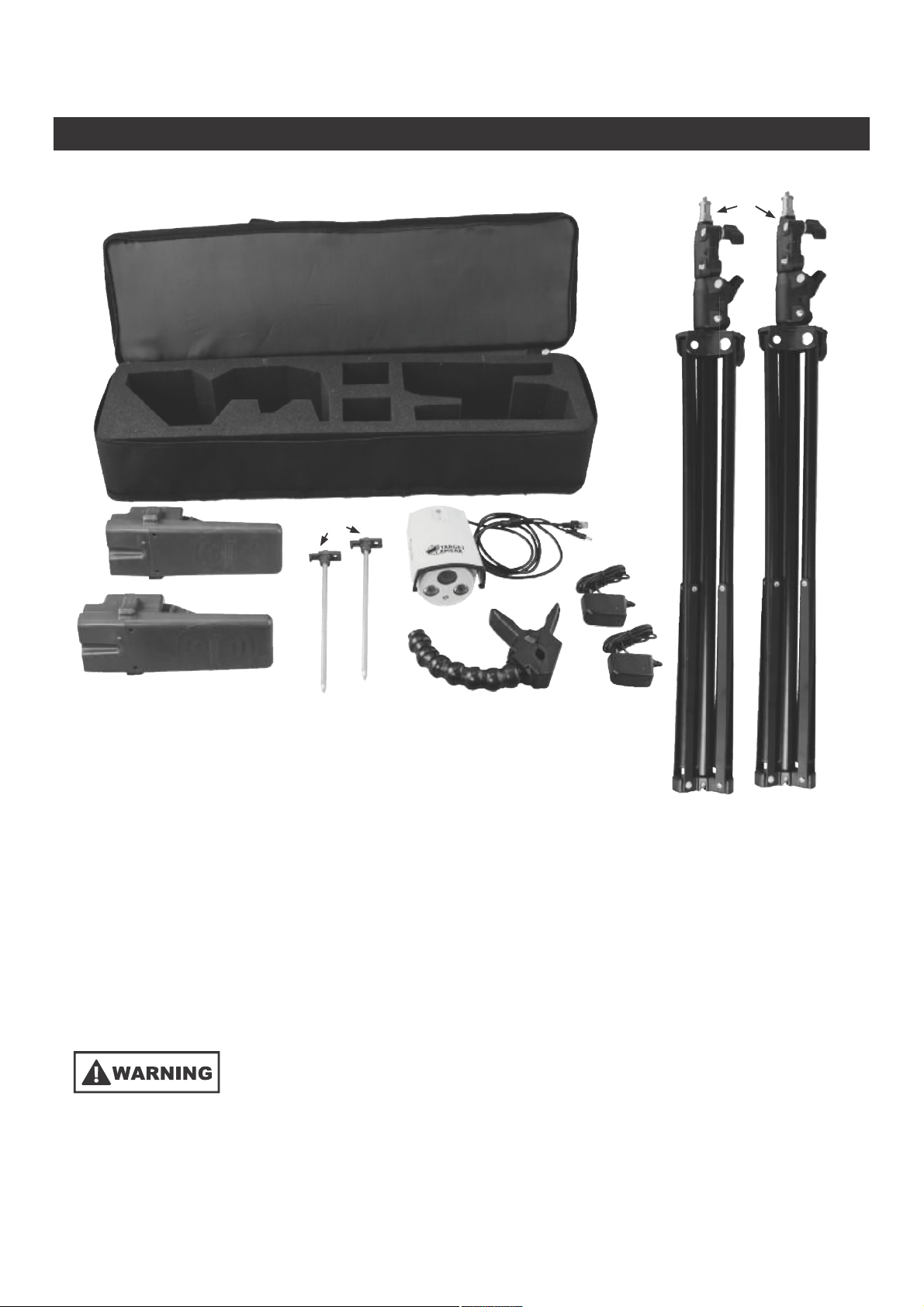
CONTENT
E.
D.
C.
F.
A.HD Camera
B.Flexible Camera Mount
C. Long Distance Transmitter
D. Long Distance Receiver
A.
G.
B.
E. 2 Router Stands
F. 2 Router Stand Stakes
G. 2 Wall Chargers
H. Storage/Carrying Case
This system is designed to deliver a live video stream of a target to the shooters
location up to one mile.
This product contains rechargeable batteries that might require
special handling at end-of-life. Please consult your local authorities for proper
recycling/disposal instructions
2

WARNINGS
could void the user’s authority to operate the equipment.
NOTE: This equipment has been tested and found to comply with the limits for a Class B digital device, pursuant to
Part 15 of the FCC Rules. These limits are designed to provide reasonable protection against harmful interference
in a residential installation. This equipment generates, uses and can radiate radio frequency energy and, if
not installed and used in accordance with the instructions, may cause harmful interference to radio
communications. However, there is no guarantee that interference will not occur in a particular installation. If
this equipment does cause harmful interference to radio or television reception, which can be determined
by turning the equipment off and on, the user is encouraged to try to correct the interference by one or more
of the following measures:
• Reorient or relocate the receiving antenna.
• Increase the separation between the equipment and receiver.
• Connect the equipment into an outlet on a circuit different from that to which the receiver is connected.
• Consult the dealer or an experienced radio/TV technician for help.
2. This device complies with Part 15 of the FCC Rules. Operation is subject to the following two conditions : (1)
this device may not cause harmful interference, and (2) this device must accept any interference received, including
interference that may cause undesired operation.
3. Shielded cables must be used with this unit to ensure compliance with the Class B FCC limits.
4. FCC RF Radiation Exposure Statement Caution: To maintain compliance with the FCC’s RF exposure guidelines,
place the product at least 20cm from nearby persons.
5. The device must not be co-located or operating in conjunction with any other antenna or transmitter.
POWER OPTIONS
Internal Lithium Ion Battery (Standard Use)
• Both the Transmitter and Receiver include integrated
Lithium Ion battery packs for ease of use. Both the
Transmitter and Receiver can operate for up to 6
hours on a single charge.
External Power Options (Extended Use)
• Only required when continuous run time is
greater than 6 hours.
• Both the Transmitter and Receiver include an external
power jack. This allows the user to utilize an external
power source. This power jack is a standard male 2.1 x
5.5mm jack.
(Photo 1)
(External battery bank
not included)
• The cord, with male 2.1 x 5.5mm jack, can be directly plugged into most standard 12V Battery Banks. (Photo 1)
• You can also connect the male 2.1 x 5.5mm jack to a fused wiring harness designed to work with terminal batteries,
such as deep cycle batteries.
3

AC Power
• This kit comes with two AC Wall Chargers. The Transmitter and Receiver can operate on the AC Wall Chargers
alone, by connecting the charger to the charge port, if AC power is available. (Photo 2)
NOTE: Never connect anything except the included
Transmitter Receiver
(Photo 2)
AC wall chargers to the charge port
Camera Power
and COM
Mounting
Point
Charge Port
External Power Jack
External
12v DC
Power
Switch Function
II O I
OFF
Internal
Battery or
AC Power
SETUP
Read through entire instructions prior to beginning setup
Smartphone Connectivity
ïò Ù± ¬± ¬¸» ¿°°®±°®·¿¬» ¿°°´·½¿¬·±² ³¿®µ»¬°´¿½» º±® §±«® -³¿®¬°¸±²»ñ³±¾·´» ¼»ª·½» ¿²¼ -»¿®½¸ º±®
•Ý¿´¼©»´´ Þ¿´´·-¬·½ Ю»½·-·±² Ì¿®¹»¬ Ý¿³»®¿Œò
îòß´¬»®²¿¬·ª»´§ô ¸¬¬°æññ©©©ò¾¬·¾®¿²¼-ò½±³ñ °®±ª·¼»- ¼·®»½¬ ´·²µ- ¬± ¬¸» ¿°°®±°®·¿¬» ¿°°- º±® ¬¸» ¼·ºº»®»²¬ ³±¾·´»
°´¿¬º±®³- -«°°±®¬»¼ ¾§ Ý¿´¼©»´´ò
íò Ѳ½» ¬¸» ¿°° ·- ·²-¬¿´´»¼ §±« ©·´´ -»» ¬¸» Ý¿´¼©»´´ Þ¿´´·-¬·½ Ю»½·-·±² Ì¿®¹»¬ Ý¿³»®¿ ¿°° ·½±² ·² §±«®
-³¿®¬°¸±²» ¸±³» -½®»»²ò
Transmitter Station Setup
• Position the Transmitter Station with consideration in
(Photo 3) (Photo 4)
avoiding likely bullet path
• Deploy Router Stand
Front
Rotate
• Attach Transmitter to Router Stand (Photo 3)
• Adjust the Router Stand, until it is level and then use one of
the Router Stand Stakes to anchor the Router Stand (Photo 4)
• Extend Stand height. For optimal performance over long
distances, extend the Router Stand height to the maximum height.
• Point the front of the transmitter towards the shooting bench (Photo 8)
• Install Camera on the Camera Mount (Photo 5)
NOTE: Storage case is designed to store the
Camera assembled on the Camera Mount
Stake next to
center pole
• Attach Camera Mount to the Router Stand at the desired height (Photo 6)
4

• Connect the Camera power connector and communication connector (Photo 7)
• Power on the transmitter, select either External or Internal power
• Connect the Smartphone/tablet to the Wi-Fi network Transmitter(Your router number will follow “Transmitter”)
(Photo 5) (Photo 6)
• Open the app, and check the alignment of the camera,
and adjust as needed. You want to adjust the camera
to center the target in the viewing window on
your device. The app allows you to zoom and pan
for additional target centering.
• Review your Transmitter Station position, as zooming
and panning may allow you to reposition if desired.
TIP: Before going up range, turn on the Receiver and
connect your phone/tablet to the Receiver to verify the
video is transmitting to the receiver
Receiver Station Setup
• Deploy Router Stand
• Attach Receiver to Router Stand (Photo 3)
• Adjust the Router Stand, until it is level and then
use one of the Stakes to anchor the Router Stand (Photo 4)
• Extend Stand height. For optimal performance over long distances,
extend the Router Stand height to the maximum height
• Point the front of the Receiver at the Transmitter (Photo 8)
• Power on the Receiver
• Connect the Smartphone/tablet to the Wi-Fi network
Receiver(Your router number will follow “Receiver”)
• The system should now be streaming a live video feed of the target
to the phone or tablet
Rotate
Camera
Power
Receiver
(Shooter Location)
Clamp to
desired height
Camera COM
(Photo 7)
Transmitter
(Target Location)
(Photo 8)
Line of sight
5
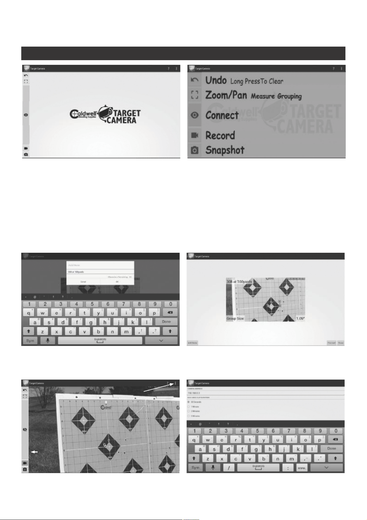
APPLICATION INSTRUCTIONS
• The app provides live stream of the target to the user
• The Connect/Disconnect button turns the camera display on/off
NOTE: This can be used as a master reset button, by cycling the camera off then back on
• The Snapshot button can be used to save a screenshot of the live video stream
• You can add a custom note to the image before saving (Example: “.308 Win, 900 Yards, Target 1)
• The Video button can be used to save a video from the live video stream
• The video length can be adjusted in the settings tab
SETTINGS TAB
6

• The Group Size calculator can be used to calculate the group size on a target
STEP 2 - Draw a line, of known length close to the group
STEP 1 - Click Zoom/Pan measure grouping icon
STEP 3 - Select all of the target hits. Click the screen to drop
STEP 3 - Enter the length of the line drawn in STEP 2
(Example: Most grid/line spacing on standard targets
are spaced at 1”)
a marker, and once the marker is dropped it can be
adjusted by clicking and dragging the marker
• Once all of the target hits have been selected, the group size will be displayed in the lower right corner
NOTE: By using the Snapshot button, you can save a screenshot of your calculated group. Only one group size can be
calculated and saved per target image screenshot.
• To clear the group, or back up one step, use the Back button or simply use the Connect/Disconnect button to
cycle the camera.
7

GENERAL RECOMMENDATIONS
• Although this system is designed to be weather resistant, it is not recommended that the device is left outside
for extended periods
• Always store your device in a dry location
• Do not submerge any of the components
• When transporting the device, use the storage/carry case to protect the components during transport
• Do not store the device with depleted batteries. It is recommended to charge the batteries before storing
for an extended period
• Use a lens cleaning cloth for cleaning the camera lens
• Clean dirt and debris off of components prior to storage, to prevent corrosion
TIPS
Power
Indicator
• Ensure clear line of sight between Transmitter and Receiver
• Extend Router Stand height to the max height
• If multiple systems are being used, take note of your router number to connect to the correct Wi-Fi network.
• When using the charger, the light on the charger will be RED during charging and GREEN when fully charged.
• Your smartphone/tablet is capable of connecting to the Transmitter or Receiver. For shorter distances, your
smartphone/tablet can connect directly to the Transmitter.
NOTE: If the video does not appear in the App, turn the Transmitter and Receiver OFF, them both
on simultaneously, and recheck the video stream.
Wi-Fi
Indicator
Camera
Indicator
8
 Loading...