


Operating Manual
UNIROB R8 – UNILOG B2
Read before using the robot and
keep it near the robot for reference purposes.
Robot - Type R8 / B2 6-10-20
Controller type UNILOG B2
Robot No.: 26358
Model: 2003
Version R82GBV00 04/03

Injection moulding
R82GBD1A.PMD
Scherl 10 • D-58527 Meinerzhagen
Battenfeld GmbH
Tel. ++49 2354/72-0 • Fax ++49 2354/72-234
Battenfeld Kunststoffmaschinen Ges.m.b.H.
Wr.Neustädter Straße 81• A - 2542 Kottingbrunn
Tel. ++43 2252/404-0 • Fax ++43 2252/404-261
www.battenfeld.com
DIN EN ISO 9001

Index
Chapter 1 General information
Chapter 2 Safety
Chapter 3 Technical Data
Chapter 4 Transport - Installation
Chapter 5 Structure and function
Chapter 6 Comissioning
Chapter 7 Maintenance
Chapter 8 Spares / Plans
Chapter 9 Customer service
?
0
Chapter 10 Extra chapter for special modules
A:PB2GBI1A.P65
B: PB2DEI1A.P65
E: 180202 / Ruder
G: 190202 / G. Krajnik
Section - IN1
Page - 1

Index
Section - IN1
Page - 2
A:PB2GBI1A.P65
B: PB2DEI1A.P65
E: 180202 / Ruder
G: 190202 / G. Krajnik

Table of contents
1.0 General
1.1 Introduction
1.2 Use
1.3 Symbols
1.4 Copyright
1.5 Confirmation of receipt
1.6 Declaration of Conformity
2.0 Safety
2.1 Safety regulations
2.1.1 General
2.1.2 Installation
2.1.3 Operation and maintenance
2.1.4 Safety - Personnel
2.1.5 Safety regulations –
Pneumatic systems
2.1.6 Safety regulations –
Electrical systems
3.2 Robot axles
3.2.1 Linear axles
3.2.2 Auxiliary axes
3.3 Performance data /
Mechanical interfaces /
Technical features
3.3.1 Linear axes (main axes)
Main axis paths – Axis
lengths
3.3.2 Drives / Repeat accuracy
3.3.3 Maximum speeds of main
and linear axes
3.3.4 Maximum speeds of rotating
and auxiliary axes
3.4 Pneumatic system
3.4.1 Compressed air connection
3.4.2 Creating a vacuum
3.4.3 Pneumatic valves
3.4.4 Pressure monitoring
3.4.5 Central configuration
3.0 Specifications
3.1 Machine description
UNIROB B2 industrial robot
3.1.1 Kinematics
3.1.2 Handling loads
3.1.3 Mechanical interface
3.1.4 Delivery side selection
3.5 Guideways on main axes
3.6 Motors / Gearing
3.6.1 Maintenance-free servo
three-phase a.c. motors for
main linear axes
3.6.2 Planetary gearing for the X
(Z) and Y and Z axis drive
A: R82GBI2A.PDM
B: R82DEI2A.PDM
E: 080403 / T. Wenger
G: 020403 / TCS
Section - TC
Page 1

Table of contents
3.7 Drive elements on main axes
3.7.1 X + Z-axis
3.7.2 Y-axis immersion pipe
3.8 Mechanical interface
3.8.1 Gripper interfaces
3.8.2 Manual gripper quick change
3.9 R8/B2 robot options
3.10 EUROMAP 12
3.10.1 Robot / Injection moulding
machine interface
3.10.2 Injection moulding machine
signals
3.10.3 Handling device signals
4 Transport - Installation
4.1 General
4.1.1 Storage
4.1.2 Unloading
4.1.3 Securing devices
4.1.4 Crane transportation
4.1.5 Transport weight
4.1.6 Injection moulding machine
assembly
?
4.1.7 Installation layout
4.1.8 External stand
4.1.9 Removing protective
coatings
4.2 Connecting to the power
supply
4.3 Commissioning
4.3.1 Connecting to the power
supply
4.3.2 Harting connector
4.3.3 Lubrication points
4.3.4 Compressed air supply
4.3.5 Activating the main switch
4.3.6 EMERGENCY STOP test
4.3.7 Power ON
5 Assembly and Operation
5.1 Modules
5.2 Pneumatic system
5.2.1 Directional control valves
5.2.2 Vacuum suction nozzle
5.2.3 Cleaner
5.3 Electrical systems
Section - TC
Page 2
5.3.1 Electric motors
5.3.2 Control cabinet
5.3.3 Terminal box 1
5.3.4 Terminal box 2
A: R82GBI2A.PDM
B: R82DEI2A.PDM
E: 080403 / T. Wenger
G: 020403 / TCS

Table of contents
5.4 Unirob B2 controller
5.4.1 Manual Control Device
(MCD)
5.4.2 PCS General
5.4.3 CP476 status display
5.4.4 CAN CP476 node number
switch
5.4.5 Digital inputs and outputs
5.5 B2 Control System
Handbook
5.5.1 Manual Control Device
(MCD) – Key functions
5.5.2 Start-up display
5.5.3 Status pages
5.5.4 Teach, Edit, Save, Load,
Delete, Print programs
5.5.5 Creating token programs
5.5.5.3 Token commands for additional devices
5.5.5.4 Palletising program
5.5.6 Examples of programs
5.5.7 Lock areas
5.5.8 Error messages
6 Operation
0
6.1 Start-up
6.2 Referencing
6.3 Manual operation
6.4 Single step mode
6.5 Automatic operation
6.6 Stopping the program
6.7 Automatic mode STOP
6.8 EMERGENCY STOP
5.5.5.1 Token commands: Gripper
(GRP), Robot (ROB),
Injection Moulding Device
(IMD)
5.5.5.2 PCS token commands
A: R82GBI2A.PDM
B: R82DEI2A.PDM
E: 080403 / T. Wenger
G: 020403 / TCS
Section - TC
Page 3

Table of contents
7 Maintenance
7.1 General
7.2 Transport, Storage and
Waste Disposal
7.2.1 Lubricants
7.2.2 Electrical components
7.3 Electrical systems
7.3.1 Electromechanical limit
switch
7.3.2 Proximity switches
7.3.3 Indicator lights
7.3.4 Control cabinet
7.3.5 Battery change
7.4 Pneumatic system
7.4.1 Compressed air servicing
unit
7.4.2 Pneumatic connections
7.5.1 X, Y and Z axis greasing
points
7.6 Drive units
7.6.1 Belt
7.6.1.1 Belt tension - X, Y, Z axes
7.6.1.2 X and Z axis belt drive
7.6.1.3 Toothed belt replacement
7.6.1.4 Noise
7.6.2 Gears
7.7 Power guide chains
7.8 Maintenance catalogue
8 Spare parts / Diagrams
9 Customer Services
7.4.3 Pneumatic C-axes
7.4.3.1 Settings C – axis (tilting)
7.4.4 Pneumatic B-axes
7.4.4.1 Settings: B - axis (swivel)
7.4.5 Pneumatic installation
components
7.4.6 Sound absorbers
7.5 Linear axis guideways
10 Additional section for
special models
Section - TC
Page 4
A: R82GBI2A.PDM
B: R82DEI2A.PDM
E: 080403 / T. Wenger
G: 020403 / TCS

Attention! Attention! Attention! Attention!
Important notes for initial operation!
A factory password is required for robot operation.
It enables the user to switch to Password level 1.
PASSWORD: 2002
Further details of the various password levels can be found in Section 5.5.2
Start-up display.
R82GBPAA.PMD


General
General
1.1 Introduction
All persons involved in the operation of the
Battenfeld robot system must read and pay
close attention to each section of this manual.
The complete manual should always be kept
near the robot system for use by machine
operators and service engineers.
The manual should be read thoroughly, paying
special attention to the Section on ”Safety”, in
order to avoid any faults occurring and ensure
smooth operation of the robot system. It is
therefore essential that the manual is available
to all persons who are responsible for operation
of the system. The manual must be studied
before start-up. We cannot accept responsibility
for any damage or stoppages which are due to
failure to read the manual.
Should you encounter any problems in operating
the robot system, please get in touch with our
Service section or one of our agents (Addresses
can be found in the ”Servicing” section).
This operating manual only applies to operation
of the robot system depicted on the title page.
Diagrams and specifications contained in this
manual are subject to change where these are
deemed necessary in improving and developing
the robot system.
1.2 Use
The Battenfeld robot system is generally used in
conjunction with other injection moulding
equipment.
The robot is not designed for any other purpose.
We cannot be held responsible for damage
resulting from improper use. Any risks incurred
in such use shall be borne by the user.
We offer operator training courses in our
company. In-house courses can also be
arranged Contact our Training Department for
further details.
A: R82GB0AA.PDM
B: R82DE0AA.PDM
E: 080403 / T. Wenger
G: 020403 / TCS
Section 1
Page 1

1.3 Symbols
The safety symbol can be found in all the work
safety regulations in this operating manual
where operators and service technicians are
exposed to the risk of physical and fatal injuries.
Follow these instructions and take extreme care
in such situations. Ensure that all other users
are familiar with the work safety instructions.
Apart from the instructions found in this
operating manual, it is also important to be
aware of general safety and accident prevention
rules.
The following safety symbols and prohibiting
signs are used on the robot system. They are
intended to warn operators and service
engineers of any dangers which may result in
physical and fatal injuries.
General
”Danger of crushing” indicates there is a risk of
being crushed.
or jammed etc.
A ”Do not enter” sign warns that a surface or
area must not be used / entered.
Attention
”Attention” is used throughout this operating
manual where it is especially important that
guidelines, rules, instructions and proper work
procedures and processes are adhered to. It is
also intended to ensure that measures are taken
to prevent the robot system from being
damaged or destroyed.
Areas labelled ”Hot surface” indicate there is a
risk of burning. Operators and service engineers
must wear suitable protective clothing (refer to
DIN EN 407).
The high voltage symbol is used in sections of
the operating manual which describe where
operators and service engineers may come into
contact with electrical components and
operating materials. It is important to ensure that
local electrical safety regulations are adhered to.
Section 1
Page 2
A: R82GB0AA.PDM
B: R82DE0AA.PDM
E: 080403 / T. Wenger
G: 020403 / TCS

General
The symbol indicating environmental hazards
indicates that there is a risk of environmental
pollution when disposing of various materials.
Local laws and regulations must be observed
when carrying out any necessary repairs or
maintenance.
1.4 Copyright
The copyrights to this operating manual are the
property of Battenfeld GmbH. The operating
manual is intended for assembly, operating and
monitoring staff. It contains regulations and
diagrams which may not be copied, distributed
or used for competitive purposes – in part or
whole - without prior authorisation, or revealed to
third parties.
1.6 Declaration of Conformity
The Declaration of Conformity can be found at
the end of this section.
1.5 Confirmation of receipt
The confirmation of receipt supplied with this
operating manual serves to verify that the
manual has been received and is complete.
Please sign the Confirmation of receipt to
confirm that you have received the complete
manual and return it to the ”Documentation”
department.
A: R82GB0AA.PDM
B: R82DE0AA.PDM
E: 080403 / T. Wenger
G: 020403 / TCS
Section 1
Page 3

General
Section 1
Page 4
A: R82GB0AA.PDM
B: R82DE0AA.PDM
E: 080403 / T. Wenger
G: 020403 / TCS

Fax transmission
General
To: BKU Documentation Department ++43/2252 404 - 3002
Confirmation of receipt
to confirm that the technical documentation has been received
by the customer
1) Robot - Type _______________________________________ Robot No.: ________________
2) Customer’s address ___________________________________________________________
____________________________________________________________________________
____________________________________________________________________________
3) The robot specified under Item 1 was acquired by our company. Upon receipt of the robot
we were supplied with ___________________________________ (quantity)
operating manual (s) in __________________________ supplied.
_________________________ ___________________________________________
Date Customer’s signature
4) Supplied: _____ ___________________________________________
5) Signature of dealer or importer:
Company stamp / signature
6) The robot was supplied to the customer in accordance with the
manufacturer’s guidelines:
_______________________________
Date Signature of service engineer
A: R82GB0AA.PDM
B: R82DE0AA.PDM
E: 080403 / T. Wenger
G: 020403 / TCS
Signature if different to 5
Section 1
Page 5

General
Section 1
Page 6
A: R82GB0AA.PDM
B: R82DE0AA.PDM
E: 080403 / T. Wenger
G: 020403 / TCS

Safety
2 Safety
2.1 Safety rules
2.1.1 General
The injection moulding machine and the robot
are fitted with numerous safety devices to
provide safe operation and to prevent accidents
occurring. The user is responsible for ensuring
that the safety devices are functioning properly.
The robot system has been designed and built
in accordance with currently valid safety
specifications (EN 201) and is an operationally
reliable machine. The system can, however, be
dangerous if it is operated by untrained persons
in an improper manner or not used for the
intended purpose.
Safe operation can only be guaranteed provided
the control program is not modified. Any
unauthorised changes made to the program
shall invalidate any guarantee claims.
The robot system must always be operated in
accordance with current environmental, safety
and accident prevention rules and the specified
operating procedures.
The user may not make any modifications or
changes which may affect the operating safety
of the system.
Intended use of the system shall include
adherence to the assembly, dismantling, startup, operation and maintenance procedures
specified by the manufacturer.
The responsible persons and the work
procedures involved in assembly, dismantling,
start-up, operation, conversion and maintenance
of the system must be recorded in the form of
general instructions.
Any modifications and changes which affect
safe operation of the system as well as all
maintenance work must be recorded in an
inspection book and kept for at least 10 years.
It is important to be familiar with the safety
regulations specified in the ”Injection Moulding
Machine” operating manual before using the
SGM with a robot system.
Before using the robot system in conjunction
with an attached peripheral device (e.g.
materials transport device) it is important to be
familiar with the safety regulations in the relevant
operating manual.
Peripheral devices may only be installed and
connected by authorised specialists.
The user is responsible for making sure that the
system is operated as specified in the operating
manual, i.e. in a safe manner in view of the
potential risks involved.
A: R82GB0BA.PMD
B: R82DE0BA.PMD
E: 080403 / T. Wenger
G: 020403 / TCS
Section 2
Page 1

Safety
Tool cranes may only be erected by authorised
persons. Cranes may only be used for the
purpose of mounting and removing tools. Do not
stand under suspended loads! The maximum
load is indicated on a sign on the crane.
The robot system must be disconnected from
all power supply sources whenever it is moved
to another location or moved only slightly.
Reconnect all the power supply points as
specified in the manual before restarting the
system.
If the robot system is transferred to a third party
or company it must be supplied with the
operating manual. We recommend you request
this be confirmed in writing.
2.1.2 Installation
Individual components, modules and the entire
robot system must be securely attached to the
lifting gear whenever any assembly,
disassembly, conversion, adjustment or
maintenance is work carried out in order to
guard against any potential hazards.
Only use suitable lifting gear which is in perfect
working order and has sufficient load capacity.
Do not stand or work under suspended loads.
Loads may only be attached, secured and
transported by experienced authorised
specialists.
The robot system may only be transported using
the eyebolts and elements specified in the
Section entitled ”Transport – Installation”.
The safety measures specified in DIN EN 292-2,
Item 6.1.2 must be taken into account before the
IMM is installed.
It is necessary to ensure that all the IMM power
sources are deactivated (electrical system) or
not in operation (pneumatic system) before
mounting the ”self-supporting protective grating”.
The safety devices must be tested after fitting or
carrying out repairs on electrical systems.
Potential risks may be created if untrained
persons are allowed to make adjustments to the
robot system in an improper manner and
without due regard to its intended use.
Adjustments may therefore only be made by
trained set-up engineers.
Set-up engineers are persons who, based upon
their specialist raining and experience, have a
wide knowledge of the materials, tools and
control systems used in robot systems and who
are also familiar with the relevant national work
protection and accident prevention regulations,
as well as guidelines and generally accepted
technical specifications, such as DIN norms.
Section 2
Page 2
A: R82GB0BA.PMD
B: R82DE0BA.PMD
E: 080403 / T. Wenger
G: 020403 / TCS

Safety
2.1.3 Operation and maintenance
Servicing may only be carried out when the
robot system is not in operation. Here, it is
important to follow the corresponding shut down
procedures.
Before carrying out any work on the robot
system make sure that the drives and auxiliary
devices are secured against accidental start-up,
e.g. by attaching a padlock to the main switch.
The safety devices must always be tested
before the robot system is restarted.
Make sure that all the safety devices are
properly attached before you restart the robot
system after carrying out maintenance work.
Check the gap between the IMM and the ”selfsupporting protective grating”. The gap must be
small enough to prevent anyone from reaching
inside. If it is too large, the grating must be
repositioned by the user.
Replacement parts must at least meet with the
technical requirements specified by the
manufacturers.
The user must ensure that electrical
components, motors etc. do not come into
contact with liquids.
Before carrying out any repairs, clean the
surrounding area thoroughly, especially the
connections and screw fittings.
Cleaning agents are toxic, inflammable liquids.
Follow the manufacturer’s instructions. Do not
use any aggressive cleaning agents. Use nonliming cleaning cloths.
Observe the relevant product safety regulations
when handling oil, grease and other chemical
substances.
The user must ensure that process materials
are disposed of in a safe, environmentally
friendly manner.
Safety devices may only be removed when the
IMM and the robot system have been shut down
and secured.
When operating the ejector mechanisms or the
core pullers with the safety door open, it is
necessary to ensure that there are no crushing
or shearing marks on the tool.
Always tighten any screw fittings which have
been slackened off during maintenance and
repair work. Check for leaking pipes, loose
screw fittings, signs of wear and damage.
Remedy any defects immediately.
A: R82GB0BA.PMD
B: R82DE0BA.PMD
E: 080403 / T. Wenger
G: 020403 / TCS
Section 2
Page 3

Safety
2.1.4 Safety - Personnel
Every person concerned with the IMM and the
robot system at the user’s plant must have read
and understood the relevant operating manual,
especially the section entitled ”Safety”. This
applies to all persons involved in assembly/
disassembly work, commissioning, operation
and repair activities (servicing, maintenance and
repairs). Users are recommended to require
this be confirmed in writing by each of the
persons concerned.
The IMM and the robot system may only be
operated, serviced and repaired by authorised,
qualified persons who have received special
training on how to deal with potential hazards.
Persons who are to be trained and instructed or
who are participating in general training courses
may only work on the IMM and the robot system
provided they are constantly supervised by
authorised, qualified persons.
When carrying out any form of assembly/
disassembly, conversion and maintenance
activities the IMM and the robot system must be
deactivated at the main switch and secured
against accidental start-up, e.g. by padlocking
the main switch.
During any work involving assembly/
disassembly, conversion, operation and
maintenance activities, inflammable liquids must
not be allowed to come into contact with
components which may create a fire hazard or
explode as a result of high temperatures.
The following systems must be allowed to cool
down to a safe temperature before carrying out
any work involving assembly/disassembly,
conversion or maintenance activities:
• Heating elements and guards.
• Temperature stabilisers, including
fittings, feeder/return pipes and
mountings.
Operators must not have long hair, wear loosefitting clothing or wear any form of jewellery or
rings. Here there is the risk of injury, e.g. getting
caught in moving parts.
Responsibility for assembly/disassembly,
commissioning. operation and maintenance
activities must be clearly defined and adhered to
in order to avoid any potential
misunderstandings with regard to safety.
• Water/heat transfer oil-filled surface
cooling on the worm cylinder (optional)
and/or worm feed zone (optional),
including all fittings, feeder/return pipes
and mountings.
• Water/heat transfer oil internal cooling on
the worm (optional), including all fittings,
feeder/return pipes and mountings.
Section 2
Page 4
A: R82GB0BA.PMD
B: R82DE0BA.PMD
E: 080403 / T. Wenger
G: 020403 / TCS

Safety
Operators must wear suitable protective
clothing to guard against burns caused by
contact with heating elements, temperature
stabilisers and their protective coverings,
fittings, feeder/return pipes and mountings as
well as electric motor housing sections (refer to
DIN EN 407).
The IMM and the robot system may only be
operated with the safety covers and doors
closed.
No work must be allowed to affect safe
operation of the IMM or the robot system.
Operators must ensure that no unauthorised
persons are allowed to work on the IMM or the
robot system.
The operator and any other persons may only
stand in front of the IMM on the operating side
whilst the machine is in operation.
Do not enter the IMM or the robot system
operating area or reach into the injection
moulding unit during operation.
Operators must always follow the shutting-down
procedures specified in the operating manual
when carrying out any work on the IMM and the
robot system.
The operator must immediately report any
changes which will affect the safety of the IMM
and the robot system. The robot system must
always be stopped immediately using the
emergency stop button and by deactivating the
main switch.
The IMM and the robot system may only be
operated when they are in perfect condition.
Users must issue the appropriate instructions
and carry out the corresponding checks to
ensure that the IMM and the robot system are
kept clean and tidy.
The operator must observe all safety
instructions and warning signs on the IMM and
the robot system. These must all be kept in a
legible condition.
Safety ladders and platforms must be used
when assembling/disassembling, converting,
operating or servicing overhead sections of the
IMM and robot system, in accordance with legal
rules and regulations. Do not climb onto any
parts of the IMM or robot system. Safety
harnesses must be worn when working at
heights.
A: R82GB0BA.PMD
B: R82DE0BA.PMD
E: 080403 / T. Wenger
G: 020403 / TCS
Section 2
Page 5

Safety
2.1.5 Safety regulations – Pneumatic
system
Compressed air pipes for the pneumatic system
must be properly routed and fitted. The fittings,
length and cross section must meet with the
requirements.
Carry out regular checks on all pipes, hoses,
and screw connections to determine any leaks
and recognisable exterior damage. Any damage
must be repaired immediately.
2.1.6 Safety regulations – Electrical system
The IMM and robot electrical system, which
have been designed and built according to
currently valid DIN EN 60204-1 and IEC 801-2
norms, are operationally reliable. Hazards may
however be created in the IMM robot’s electrical
system if it is improperly operated by untrained
persons or used for purposes other than its
intended use. All assembly/disassembly,
conversion and maintenance work may
therefore only be carried out by electricians
(according to DIN VDE 0105 or DIN EN 60204-
1).
The electrical system may only be connected to
a power supply of a current type, voltage and
frequency which corresponds to the
specifications on the robot system rating plate.
Electrical feeder cables must meet with the
specified requirements.
Shut down the robot system at the main switch
before carrying out any assembly/disassembly,
conversion or maintenance work. Make sure
that the electrical system is de-energised,
earthed and short-circuited.
The electrical system must be checked
regularly. Any defects such as loose
connections or burned cables must be
remedied immediately.
For safety reasons, the operator must log off the
control system after completing the set-up
operation in order to prevent unauthorised
persons from specifying any other values.
Legal rules and regulations must be observed
when carrying out any assembly/disassembly,
conversion or maintenance work.
Section 2
Page 6
A: R82GB0BA.PMD
B: R82DE0BA.PMD
E: 080403 / T. Wenger
G: 020403 / TCS

Specifications
3 Specifications
The ”Specifications” section contains all the
required technical data which are usually
required for installation, start-up and operation of
the UNIROB B2 industrial robot.
3.1 UNIROB B2 Industrial robot
The UNIROB B2 industrial robot was developed
for automation of injection moulding machines
with medium clamping forces of up to 3500 kN
(385 sh tn).
3.1.1 Kinematics
The kinematic structure of the UNIROB B2
comprises a portal robot whose main axes
consist of two horizontally aligned unsupported
linear axes (X/Y) and a vertically aligned linear
axis (Y). It has a maximum of two (B/C)
auxiliary axes.
3.1.2 Handling loads
The rated and maximum load (operating
load) is 8 kg (18lb) for the component and
gripper.
3.1.3 Mechanical interface
The robot is supported by a torsion-free base
which is mounted on the IMM injector plate. The
mechanical interface can be attached to the
Battenfeld injection moulding machine and to
machines with Euromap drilling patterns.
3.1.4 Delivery side selection
Component delivery is at the rear of the IMM.
The linear axes (main axes) are driven by
electric motors whilst the B and C auxiliary axes
are pneumatically driven.
A: R82GB0CA.PDM
B: R82DE0CA.PDM
E: 080403 / T. Wenger
G: 020403 / TCS
Section 3
Page 1

Specifications
3.2 Robot axis definitions
The axes are defined according to a fixed
cartesian co-ordinate system made up of the
horizontal X and Z axes and the vertical Y axis.
Industrial robots are, in a broader sense,
numerically controlled machines. The axes are
therefore defined as in DIN 66 217.
Extensive use of DIN 66 025 creates a uniform
addressing system for the purpose of controlling
the axes.
3.2.1 Linear axes
The following linear and main axes are driven by
electric motors:
X main horizontal linear axis parallel to the
first axis of the reference co-ordinate
system (IMM longitudinal direction)
3.2.2 Auxiliary axes
The following rotating and auxiliary axes are
pneumatically driven:
B auxiliary axis parallel to the Y-axis or
other main rotating axis
C auxiliary axis parallel to the Z-axis
The most common axes are shown in the ”Axis
definition” diagram below.
Z main horizontal linear axis parallel to the
second axis of the reference co-ordinate
system (IMM transverse direction)
Y main vertical linear axis parallel to the
third axis of the reference co-ordinate
system
R8B2_001.JPG
The axis letter symbols are positioned at
suitable, clearly visible points to indicate the type
and direction of movement of each axis.
Section 3
Page 2
A: R82GB0CA.PDM
B: R82DE0CA.PDM
E: 080403 / T. Wenger
G: 020403 / TCS

Specifications
p
(Op
p
3.3 Performance data /
Mechanical interfaces /
Technical features
3.3.1 Linear axes (main axes) Main axis
paths – Axis lengths
R8 / B2
Robot
B2 4-8-15
B2 6-10-20
B2 6-12-25
mm
mm
mm
inch
inch
inch
3.3.2 Drives / Repeat accuracy
The main axes (X/Y/Z) are driven by a servo
three-phase a.c. motor.
Travel: Axis sequencing of the main and linear
axes.
The Y-axis is fitted with an immersion pipe.
400
600
600
X-axis Y-axis Z-axisUnits
15,7
23,6
23,6
800
1000
1200
31,5
39,4
47,2
1500
2000
2500
R8B2_GB002.XLS
59,1
78,7
98,4
3.3.3 Maximum speeds of main and linear
axes
Units X-axis Y-axis Z-axis
m/s
inch/s
118,1
3
157,5
4
126
3
R8B2_GB003.XLS
Position detection:
ACOPOS servo-assisted (B&R drive
mechanism)
refer to 5.3.1"Electric motors“.
3.3.4 Maximum speeds of rotating and
auxiliary axes
Axis
Turning
angle
C90° 90 °/s
B
tion)0° - 90° 90 °/s
max.
speed
Drive
neumatic
neumatic
R8B2_GB004.XLS
The performance data apply at a minimum
operating pressure of 6 bar (87 psi).
The repeat accuracy of +/- 0.1 mm (+/- 0.004
inches) is based upon the centre of the gripper
mounting.
A: R82GB0CA.PDM
B: R82DE0CA.PDM
E: 080403 / T. Wenger
G: 020403 / TCS
Section 3
Page 3

Specifications
3.4 Pneumatic system
3.4.1 Compressed air connection
The compressed air servicing unit for non-oil
compressed air is fitted with a pressure
regulator valve and a gauge which keeps the
operating pressure constant virtually all the time.
The minimum operating pressure is 6 bar (87
psi). Pressure losses and fluctuations make it
necessary to set the supply pressure at the
control valve to 6 bar (87 psi). ( refer to Section
7 Maintenance/Repairs).
The available initial pressure must not be
allowed to fall below 7 bar (102 psi) and or
exceed 12 bar (174 psi).
The pressure control valve is not designed to be
able to deenergise the system pneumatically.
This is done by activating the electrical main
switch via the main valve which then vents the
system.
3.4.2 Creating a vacuum
3.4.3 Pneumatic valves
The system uses pneumatic 5/2-way valves
with multiple mounting plates. The integrated
vacuum nozzle in the valve block means that it
can only be used with oil-free air.
The vacuum valve air consumption is 27 l/min
(7.13 US gallons).
3.4.4 Pressure monitoring
The standard pneumatic system is fitted with a
pressure switch which acts as a pneumaticelectronic converter (closer). If the pressure falls
below the 3 bar (44 psi) setting the robot sends
out a fault signal.
This is indicated in the display. The pneumatic
axis and gripper functions cannot operate safely
if the supply pressure drops below the specified
setting. The user shall be liable for any
consequential damage.
3.4.5 Central configuration
All the pneumatic elements are located on the
Z(X) slide except for the servicing unit.
The vacuum which is required to operate the
gripper is created using a vacuum injector
(Venturi principle). A blow out function is used to
place the components in the correct position.
Section 3
Page 4
A: R82GB0CA.PDM
B: R82DE0CA.PDM
E: 080403 / T. Wenger
G: 020403 / TCS

Specifications
3.5 Guideways on main axes
All the main linear axes have guiderails and S
(standard) precision circulating ball steering,
with a max. 0.01 mm (0.0004 inch) play and no
pretensioning.
Each of the guide units running along the ground
guiderails with hardened tracks has 4 rows of
balls.
The guiderails and guide units can be replaced
separately. The reversing flaps on the guide
units have an integrated sealing lip and a forcefeed lubrication nipple or a connector for the
central lubrication circuit.
3.6 Motors / Gearing
3.6.1 Maintenance-free servo three-phase
a.c motors for main linear axes
The servo drives produce a constant sustained
torque over the entire speed range up to a
maximum ambient temperature of 45°C (113°F).
This produces a motor temperature of 60°C
(140°F) depending upon the thermal motor time
constant.
3.6.2 Planetary gearing for the X (Z) and Y
and Z axis drive.
• single stage
• Circumferential backlash < 8 angular
minutes
• Max. input speed of 4500 rpm.
• 94-97% efficiency at a max. operating
temperature of 100°C (212°F)
• Shaft linked to motor by a clamping hub
(sleeve shaft)
• Smooth drive shaft with clamping hub
link
The servo controlled axle drives are fitted with
integrated motor brakes which are activated at
the end position.
Standard high quality bearings permit speeds
ranging from approx. 1 revolution per day up to a
maximum of 4000 rpm (depending upon the
gearing).
• Maintenance-free synthetic oil (refer to
Section 7).
A: R82GB0CA.PDM
B: R82DE0CA.PDM
E: 080403 / T. Wenger
G: 020403 / TCS
Section 3
Page 5

Specifications
3.7 Drive elements on main axes
3.7.1 X and Z axis
The power transmission and conversion from
rotary to linear movement is produced by means
of a toothed belt which is clamped to the slide, a
pinion attached to the gearing drive shaft and a
bearing-mounted deflection roller at the end of
the axis.
3.7.2 Y-axis immersion pipe
The power transmission and conversion from
rotary to linear movement is produced by means
of a toothed belt clamped to the immersion pipe
and a pinion attached to the gear shaft.
3.8 Mechanical interface
3.8.1 Gripper interface
The gripper flange measures 80 x 80 mm (3.15
x 3.15 inches) with a centred M6 – 40 x 20 (1.57
x 0.79 inches) drilling pattern and 60 x 25mm
(2.36 x 0.98 inches) spacing.
The quick-fitting coupling for the vacuum action
and the gripper compressed air connectors are
located on the pneumatic connecting block.
3.8.2 Manual gripper quick change
A optional manual quick change gripper device
is available for frequent gripper changes.
It is possible to change the gripper in approx. 1
minute by pushing it into the dovetail guideway
and then securing it with clamping elements.
Two mounting plates are supplied with the
gripper.
Section 3
Page 6
A: R82GB0CA.PDM
B: R82DE0CA.PDM
E: 080403 / T. Wenger
G: 020403 / TCS

Specifications
3.9 R8/B2 robot options
Description of options
RA B02 B-axis, pneumatic 0° - 90°
RM C03
RG M01 Gripper quick change100x100
RP D02 Additional clamp circuit
RP D02 Additional vacuum circuit
RE L01 Equipped acc. NFPA
Quick change flange, C-axis
(manual fasr change flange, ds/ss)
R8B2_GB005.XLS
3.10 EUROMAP 12
3.10.1 Robot / Injection moulding machine
interface
The 32-pin HAN 32A plug connector is used to
provide a secure link between the injection
moulding machine (IMM) and the handling
device (HD). HD contacts and contacts inside
the IMM are all floating and can be used with
maximum loads of 64V/200mA.
3.10.2 Injection moulding machine signals
01/09 EMERGENCY STOP (IMM)
The contact must be opened by the
EMERGENCY STOP switch on the IMM.
02/16 Start handling procedure
(IMM)
Start HD approach. The signal from the IMM
indicates that the contact is closed when the
minimum width for forward movement has been
reached. It must not be possible to accidentally
adjust the opening to a narrower setting than the
minimum required tool width.
The signal must be indicated while the tool is
open. It must not be interrupted if the machine is
switched to a different mode or when the guard
door is opened. Damage may occur if the signal
is indicated too early (incorrect or accidental
adjustment of the limit switch or position
encoder signal).
The pin assignment of the plug connector
between the injection moulding machine and the
handling device is as in EUROMAP 12.
03/11 Guard doors closed
(IMM)
Forward/Backward movement of the HD is
prevented. The contact is closed when the IMM
guard doors are closed (and the anti-slip device
is not activated).
04/16 Ejector retracted (from IMM)
The IMM signals that the ejector has been
retracted regardless of the position of the
moveable mounting plate.
A: R82GB0CA.PDM
B: R82DE0CA.PDM
E: 080403 / T. Wenger
G: 020403 / TCS
Section 3
Page 7

Specifications
05/16 Ejector forward (from IMM)
IMM signals that the ejector is forward.
06/16 Core pullers released, HD can move
in (IMM)
The IMM signals to the HD that the core pullers
are in position to allow the removal device to
enter (regardless of the position of the mounting
plate).
07/16 Core pullers in removal position
(IMM)
The IMM signals to the HD that the core pullers
are in position to remove the casting.
08/16 Defective casting (from IMM)
The IMM signals to the HD that the removed
casting is defective. The signal must be
triggered by ”Tool open” and can be reset by
”Close tool”.
10/16 IMM Fully automatic mode (from IMM)
The IMM signals to the HD that the operating
mode selector is set to ”Fully automatic”.
3.10.3 Handling device signals
17/32 Start Tool close sequence (by HD)
Activate Tool close: The contact is closed when
the HD has been extended to the point where
the tool can be closed and when other HD
control devices activate the Tool close
sequence.
This contact is only bypassed automatically
when the IMM is operated without the HD.
It must not be possible to activate the Tool close
action when closing the guard door, in manual
operation or by using the ”OR” function button.
The signal is activated during the closing
sequence. If the signal is cancelled, the closing
movement must be interrupted.
18/26 Tool area monitoring free (HD)
Open/close tool monitoring: The contact is
made by the limit switch on the positioning slide.
The limit switch is activated when the
positioning slide leaves its starting position in the
IMM area (before it enters the tool area). If the
link is open, the IMM can neither be opened or
closed. The contact can also be made without
the HD.
12/16 Tool closed (IMM)
The IMM signals to the HD that the closing
sequence has been completed. The ”Start
closing” signal is then cancelled.
Section 3
Page 8
A: R82GB0CA.PDM
B: R82DE0CA.PDM
E: 080403 / T. Wenger
G: 020403 / TCS

Specifications
19/27 EMERGENCY STOP (HD)
The IMM control system is deactivated when the
contact is opened. The contact must be in
series with the IMM EMERGENCY STOP.
20/32 Handling device operation (HD)
Operating mode switch: Opened contact signals
to IMM: Operation with HD (Position 1).
Closed contact signals to IMM: Operation
without HD (Position 0).
21/32 Ejector retracted (from HD)
The closing contact returns the tool ejector.
22/32 Ejector forward (from HD)
The closing contact moves the tool ejector
forward.
23/32 Core pullers in removal position
(from HD)
Move core pullers into position to remove the
moulded component.
24/32 Core pullers retracted (from HD)
Move core pullers into position to move in the
HD.
A: R82GB0CA.PDM
B: R82DE0CA.PDM
E: 080403 / T. Wenger
G: 020403 / TCS
Section 3
Page 9

Specifications
Section 3
Page 10
A: R82GB0CA.PDM
B: R82DE0CA.PDM
E: 080403 / T. Wenger
G: 020403 / TCS

Transport - Installation
4 Transport - Installation
4.1 General
Upon delivery, the handling device (hereafter
referred to as the ”robot”) it must be checked
immediately for any damage and for
completeness.
The scope of delivery also includes:
• Operating Manual
• Data carriers with the required
software
• Dummy plugs for bypassing
EMERGENCY STOP
(refer to 4.3 Commissioning)
All keys, e.g. for the switch cabinet, enclosures
etc. can be found at the main switch.
We recommend you arrange for the robot to be
assembled by Battenfeld engineers. We cannot
accept liability for any damage resulting from
improper assembly.
4.1.1 Storage
All robots are adequately packaged in order to
prevent any damage occurring in transit. The
robot must be put into operation immediately
after it has been delivered by the transport
company.
Contact our Customer Services department if
the robot is to be stored for a prolonged period
of time.
4.1.2 Unloading
We cannot guarantee the robot will function
perfectly or accept any guarantee claims
unless it has been unloaded in the proper
manner.
The robots may only be transported and
lifted horizontally on the special transport
and loading elements The lifting gear must
be secured to prevent it from slipping.
The crane carrying capacity and the lifting
gear must be at least the same weight as the
robot. (refer to Installation layout– Section
3.0 Specifications)
A: R82GB0DA.PMD
B: R82DE0DA.PMD
E: 080403 / T. Wenger
G: 020403 / TCS
Do not stand inside the danger area around
suspended loads!
Section 4
Page 1

Transport - Installation
4.1.3 Securing devices
All forms of securing devices (ropes, cable
ties, adhesive tape etc.) must be removed
before commissioning. They must always be
reattached before the machine is
transported again.
4.1.4 Crane transportation
4.1.6 Injection moulding machine assembly
Safety ladders and platforms must be used
when assembling/disassembling,
converting, operating or servicing overhead
components belonging to the robot in
accordance with legal regulations and
specifications. Do not climb onto any of the
robot components. Safety harnesses must
be worn when working at heights.
If the robot is mounted on the injection moulding
machine, it is important to ensure that the
machine is aligned to within 0.1 mm (0.004
inches). (refer to the IMM Operating Manual –
Section 4: Transport - Installation).
4.1.7 Installation layout
The precise space requirements are specified in
the ”Installation layout” diagram at the end of this
section.
4.1.5 Transport weight
Model S Length Width Height
R8 4-8-15 B2
R8 6-10-20 B2
R8 6-12-25 B2
Control cabinet B2
Section 4
Page 2
400 kg 2700 mm 1600 mm 1800 mm
882 lbs 106.3 inch 63 inch 70.9 inch
430 kg 3200 mm 1800 mm 2000 mm
984 lbs 126 inch 70.9 inch 78.7 inch
460 kg 3700 mm 1800 mm 2200 mm
1014 lbs 145.7 inch 70.9 inch 86.6 inch
30 kg 700 mm 600 mm 300 mm
66 lbs 27.6 inch 23.6 inch 11.8 inch
R8B2_164.PDF
R8B2GB_165.XLS
A: R82GB0DA.PMD
B: R82DE0DA.PMD
E: 080403 / T. Wenger
G: 020403 / TCS

Transport - Installation
4.1.8 External stand
If external stands are used, make sure that the
robot can be positioned horizontally on the
stands.
Smooth operation cannot be guaranteed unless
the robot is mounted in a horizontal position.
4.1.9 Removing protective coatings
Remove the rust protection agent from all
polished, moving parts and guideways, as well
as all non-coated and non-galvanised bolts. Use
cleaning cloths soaked in degreasing solvents,
benzine, petrol or similar agents.
These cleaning agents are toxic,
inflammable liquids. Pay attention to the
manufacturer’s instructions!
4.2 Connecting to the power
supply
The robot may only be connected up to power
supplies which conform with the current type,
voltage and frequency specified on the rating
plate (control cabinet).
It is important that users comply with
national regulations relating to earthing and
protective measures (overcurrent and
residual-current protection devices) in TN, IT
and TT systems. External and neutral
conductors (IT systems) and must be
protected against short-circuiting as
specified on the rating plate.
Conventional protective multiple earthing
(PEN conductors) may not be used. PE
conductors and N conductors (if required)
must always be connected separately.
It is also important to observe local
regulations relating to the disposal of such
liquids and impregnated cleaning cloths!
A: R82GB0DA.PMD
B: R82DE0DA.PMD
E: 080403 / T. Wenger
G: 020403 / TCS
Section 4
Page 3

Transport - Installation
Attach the outer conductors to the terminals
inside the control cabinet.
Attachment type:
Feeder + neutral conductor
L1a
L2a L3a N
5(L1, L2, L3, N, PE)
R8B2_006.BMP
Main incoming supply. Refer to the circuit
diagram on Sheet B1. No.: 10
X1
4.3. Commissioning
Before you start the commissioning
procedure, it is important to read and make
sure that you have understood all the items
contained in the ”General” and ”Safety”
sections.
This section deals with the key points to be
observed when activating the electrical systems
for the first time. It is important to adhere to each
of these points in order to ensure that the
machine runs properly.
4.3.1 Connecting to the power supply
Connect up the power supply to terminal row X1
using a 5 x 6 mm2 cable as described in 4.2..
4.3.2 Harting connector
The Harting connector point is located on the
side of the control cabinet.
18X0 HAN6 - Hand control
12X2 HAN10 - 3 x 400 V power supply
Servo booster
21X0 HAN16 - 24V DC power supply
CAN
100X1 HAN24 - Interface
Service door
80X1 HAN32 - IMM interface
Sections of the control cabinet are shown in the
circuit diagram on Sheet 71 and in Section 5
Assembly and Operation, 5.3.2 Switch cabinet.
Section 4
Page 4
A: R82GB0DA.PMD
B: R82DE0DA.PMD
E: 080403 / T. Wenger
G: 020403 / TCS

Transport - Installation
If no peripheral device is used or if there is
no service door, it is important that the
supplied dummy plugs for bypassing the
EMERGENCY STOP are connected.
The plugs can be clearly identified by the
coded sockets and pins.
4.3.3 Lubrication points
Check all lubrication points.
4.3.4 Compressed air supply
Connect the compressed air supply to the robot
service unit and adjust to 6 bar (87 psi). Refer to
Section 2.0 Safety, 2.1.5 Safety regulations –
Pneumatic systems.
4.3.5 Activate main switch
Activate the main switch on the control cabinet
to start the control system. The motors are
initially interrupted by the main fuse (40 K1).
4.3.6 EMERGENCY STOP test
To test the EMERGENCY STOP
(hardware and software) on the
manual control device, press and
release the button. Also check that
all the other EMERGENCY STOP
devices (IMM, Periphery) are
released. This procedure must be repeated
each time the main switch is activated/
deactivated.
4.3.7 Power ON
After checking the EMERGENCY
STOP line and activating the slam
button, press the START button
together with the TOTMANN button
on the MCD and observe the robot
(visual check).
Once all the initial start-up steps have been
carried out, the main contactor (40 K1) activates
the power supply at the ACOPOS servo booster.
The motor holding brakes remain activated. The
three servo axes are not controlled. (Axis
sequencing)
A: R82GB0DA.PMD
B: R82DE0DA.PMD
E: 080403 / T. Wenger
G: 020403 / TCS
Section 4
Page 5

Transport - Installation
Section 4
Page 6
A: R82GB0DA.PMD
B: R82DE0DA.PMD
E: 080403 / T. Wenger
G: 020403 / TCS

Assembly and Operation
5 Assembly and
Operation
5.1 Modules
1 Pneumatic system (refer to 5.2)
2 Electric motors (refer to 5.3.1)
3 Terminal box 1 (refer to 5.3.3)
4 Terminal box 2 (refer to 5.3.4)
?
4
2
3
1
A: R82GB0EA.PMD
B: R82DE0EA.PMD
E: 170403 /T. Wenger
G: 020403 / TCS
Section - 5
Page - 1

?
Assembly and Operation
5.2. Pneumatic system
The pneumatics are a key component of the
robot system. They provide a ”source of energy”
for the auxiliary axes and the gripper clamping /
vacuum circuits.
5.2.1 Directional control valves
These valves shut off, release and divert the
compressed air channels.
Electromagnetic valve
These valves adjust the auxiliary axes (basic
and end positions) and set/reset the clamping
circuits.
Solenoid valve
R8B2_010.PDF
Principle:
Electrically activated 5/2 monostable directional
control valve Once it has been set, the valve
only remains in position while the adjusting
signal is activated. A mechanical spring resets
the valve when the signal is deactivated.
5.2.2 Vacuum suction nozzle
R8B2_009.PDF
Principle:
Electrical, indirectly activated 5/2 bistable,
directional valve. The valve remains in position
after it has been adjusted until it is reset by a
counter signal.
R8B2_011.PDF
A vacuum is created inside the vacuum
generator by the compressed air passing
through it (Venturi principle). The vacuum
generator is switched on/off by an input signal.
The housing has an integrated filter to keep out
any dirt.
Section - 5
Page - 2
A: R82GB0EA.PMD
B: R82DE0EA.PMD
E: 170403 /T. Wenger
G: 020403 / TCS

Assembly and Operation
?
5.2.3 Maintenance unit
1
2
3
1 - Pressure control valve
adjusting knob
2 - Condensate drain
3 - Pressure gauge
4 - Condensate tank
5 - Drain plug
4
5
R8B2_133.PDF
The cleaner removes any liquids and solid
materials in the compressed air flow and
regulates the air pressure.
The cleaner may only be used with properly
processed compressed air which does not
contain any aggressive agents.
A filter and a water separator remove any solid
particles and water from the compressed air.
This protects the downstream pneumatic
elements from premature wear.
5.3. Electrical systems
5.3.1 Electric motors
R8B2_013.PDF
General:
The three linear axes on the 3-axis handling
device are driven by three motors which are
controlled by a digital servo booster. (B&R/
Type:8V1090.00-2)
Axis change-over:
The motors are activated together with the required
digital inputs/outputs. (e.g. HW limit switch)
The drive is not controlled when it is not moving.
The holding brake keeps the axis in position when
the servo booster is not activated.
Attention!
The robot system pneumatics may only be
operated using oil-free air!
The booster communicates with the CP276
controller via CAN. (refer to Section 5.4.2 PCS)
Connections are specified in Section 4.2 Transport
and Installation – Electrical connections.
Electrical components may only be serviced
by qualified electricians!
A: R82GB0EA.PMD
B: R82DE0EA.PMD
E: 170403 /T. Wenger
G: 020403 / TCS
Section - 5
Page - 3

?
5.3.2 Control cabinet
The control cabinet is located near the robot
system. It must be mounted in an easily
accessible position.
Assembly and Operation
1 Socket
2 Printer interface or floppy disc
DSUB9
3 Main switch
4 Conveyor belt cable gland
5 Peripheral cable gland
6 Power supply (3x400V) cable gland
7 HAN_E plug, power supply connection
3x400V ACOPOS servo booster
Section - 5
Page - 4
R8B2_014.PDF
8 HAN24 operating door interface
9 Injection moulding machine interface
EUROMAP12 HAN32
10 HAN16_E plug, 24 V DC power supply
for Terminals 1, 2 and CAN
11 HAN6 manual control panel with 24-pin
contact unit
Attention!
Refer to the circuit diagram for details of the
individual plugs!
A: R82GB0EA.PMD
B: R82DE0EA.PMD
E: 170403 /T. Wenger
G: 020403 / TCS

Assembly and Operation
?
5.3.3 Terminal box 1
Terminal box 1 is located at the end of the main
axis support. It contains the servo booster as
well as the motors and sensor analysis changeover.
Do not alter change the shielding on the
motor cables!
The fan inside the terminal box must be
switched on in order to prevent the ACOPOS
servo booster from overheating.
Basic design of the B&R 8V1090.00-2 servo
booster:
The LED is illuminated when the ACOPOS
servo booster is connected to the 24 V DC
power supply.
LED Description Colour
1 Ready green
2 Run orange
3Errorred
R8B2_GB016.XLS
After switching off the devices the intermediate
circuit requires a discharge time of at least 5
minutes. Use a suitable measuring device to
check that the current intermediate circuit
voltage is below 24 V DC to ensure that the
system is safe before carrying out any work. If
the LED indicator is extinguished this does not
necessary mean that the device has been
deenergised!
Signal LED
Ready green
R8B2_GB130.XLS
R8B2_015.PDF
Description:
Illuminated when the ACOPOS servo booster is
ready for operation and the power stage can be
activated. (Operating system available and
booted up, no permanent or temporary faults
detected).
3
Signal LED
2
1
Run orange
R8B2_GB131.XLS
Description:
Lights up when the ACOPOS servo booster
power stage is activated.
4
A: R82GB0EA.PMD
B: R82DE0EA.PMD
E: 170403 /T. Wenger
G: 020403 / TCS
Section - 5
Page - 5

?
Assembly and Operation
Signal LED
Error red
R8B2_GB132.XLS
Description:
Lights up when there is a fault at the ACOPOS
servo booster. The LED is extinguished
automatically once the fault has been remedied.
t
Permanent faults include:
Motor feedback interrupted or not
connected
Low level at Enable input
Motor temperature sensor not connected
Internal fault
Temporary faults include:
24 V DC voltage supply or intermediate
circuit voltage is outside of the tolerance
range
Internal 15 V DC voltage supply is
outside of the tolerance range
Motor overheated
Servo booster overheated
LED indicators:
Red LED: Power is switched off. Green LED:
POWER ON and system stationary.
During adjustment, i.e. when an axis is moving,
the green and orange LEDs are illuminated.
The servo booster has four card sockets. All
four sockets are used in this application:
1. Socket AC110:
CAN interface
2.3.4 Socket AC112:
3 Resolver cards
5.3.4 Terminal box 2
Terminal box 2 is located on the main slide and
contains the following Beckhoff components:
LS5100 CAN coupler
KL1104 input terminals.
KL2134 output terminals.
The input and output terminals are read in and
triggered by the CP476 controller via CAN.
Braking resistance overheated, CAN or
powerlink network fault.
Section - 5
Page - 6
A: R82GB0EA.PMD
B: R82DE0EA.PMD
E: 170403 /T. Wenger
G: 020403 / TCS

Assembly and Operation
?
LS5100 transceiver
24 V DC power supply
(See circuit diagram for details of connections)
The two K bus LEDs indicate the operating
statuses of the bus terminals and the
connections to them.
Green LED illuminated: In operation, no faults.
Red LED flashing. Fault signal. Two different
frequencies.
Address
selector
Configuration
interface
left: Field bus LED
right: C bus LED
K bus
left: CAN-H
right: CAN-L
V+
Transceiver
supply
Faults are coded as follows:
Fast flashing Error code start
1st. slow sequence Error code
2nd. slow sequence Error cause
R8B2_GB018.XLS
Error code Error cause
1 pulse 0 1 2
R8B2_GB154.XLS
Description:
0 EEPROM check sum fault
1 Inline Code Buffer overrun
2 Unknown data type
Error code Error cause
2 pulse 0 n(n>0)
R8B2_GB155.XLS
Description:
Programmed configuration
Incorrect table entry / bus coupler Table
comparison (Terminal ”n”) incorrect
V-
Shield
Power contacts
R8B2_017.PDF
Error code Error cause
3 pulse 0
R8B2_GB156.XLS
Description:
Terminal bus command fault
Error code Error cause
4 pulse 0 n
R8B2_GB157.XLS
Description:
Terminal bus data error: Breakage behind
Terminal ”n” (0: coupler)
A: R82GB0EA.PMD
B: R82DE0EA.PMD
E: 170403 /T. Wenger
G: 020403 / TCS
Section - 5
Page - 7

?
Assembly and Operation
Error code Error cause
5 pulse n
R8B2_GB158.XLS
Description:
Terminal bus fault in signal communication with
terminals
Error code Error cause
7 pulse n
R8B2_GB159.XLS
Description:
Non-supported terminal at ”n”.
KL1104 input terminals
Signal – LED 1
Signal – LED 3
E1
A
B
1
C
D
5
E2
KL2134 output terminals
Signal – LED 1
Signal – LED 3 Signal – LED 4
A1
Power-
contacts
A3 A4
A
CD
1
2
3
4
Top view
B
Signal – LED 2
5
A2
6
+24 V
7
0 V
8
R8B2_020.PDF
2
Power-
contacts
E3 E4
3
4
Top view
6
7
8
R8B2_019.PDF
Section - 5
Page - 8
A: R82GB0EA.PMD
B: R82DE0EA.PMD
E: 170403 /T. Wenger
G: 020403 / TCS

Assembly and Operation
?
5.4. Unirob B2 controller
The Unirob B2 is straightforward and easy to
operate.
The main axes and auxiliary axes are regulated
by a sophisticated control system.
The sequential programming process (hereafter
referred to as token programming) is structured
in a simple format which is easy to understand.
This program also facilitates universal usage.
The current token program can be saved to a
floppy disc via an RS232 interface or printed out.
5.4.1 Manual Control Device (MCD)
The MCD consists of:
• LCD (approx. 2.76") with 8 x 21
character lines.
• Green START button and a red
EMERGENCY STOP slam button.
• Four function keys (F1 to F4) for
selecting the various functions.
• Two cursor keys on either side of the
display, ON/OFF (right) and START/
STOP (left).
• A ”Num.” key for switching the numeric
pad (0-9) on/off.
• Four positioning keys for controlling the
movement and speed of the axes.
• Seven object selection keys (e.g.
gripper, IMM etc.) for use in Manual
mode and token programming.
R8B2_021.JPG
The MCD key configuration and functions are
explained in Section 5.5 Handbook.
A: R82GB0EA.PMD
B: R82DE0EA.PMD
E: 170403 /T. Wenger
G: 020403 / TCS
Section - 5
Page - 9

?
Assembly and Operation
5.4.2 PCS General
The CP476 B&R SYSTEMS 2003 comprises a
sophisticated central component of the robot
system.
Features:
750 kByte User SRAM
1.5 mByte User FlashPROM
CP interface with four module slots
Two node number switches
The CP476 central unit has a system bus for
additional expansion units. Two CAN node
number switches eliminate the need for offset
adjustments. The actual node number always
corresponds to the switch position.
5.4.3 CP476 status display
R8B2_021.JPG
LED Colour Decription
CAN orange Data flow from/to CAN controller
RS232 orange
ERR red
RUN green
RDY green Lights up in Service mode
MODE green
1, 2, 3, 4 orange
Indicates whether data are
received/sent
Lights up in Service mode and if a
fault occurs
Lights up in RUN and in Service
mode
Lights up during FlashPROM
programming
LEDs indicate operating status of
each adapter module.
R8B2_GB023.XLS
Section - 5
Page - 10
A: R82GB0EA.PMD
B: R82DE0EA.PMD
E: 170403 /T. Wenger
G: 020403 / TCS

Assembly and Operation
?
RS 232 interface
Interface
User interface RS232
9-pin 7 RTS
DSUB plug 8 CTS
1NC
2RXD
3TXD
4 + 5 VCD/max. 500 ma
5GND
6NC
9NC
Connection configuration
RS232
Receive Signal
Transmit Signal
Panelboard power
Request To Send
Clear To Send
Reserved
Ground
Reserved
Reserved
R8B2_GB028.XLS
The non-isolated RS232 interface is used for
programming the central unit or the signal is
transferred to the disc drive and the printer
interface at the control cabinet.
5.4.4 CAN CP476 node number switch
R8B2_029.JPG
The CAN node number is adjusted using the two
HEX switches.
The switch positions can be determined at any
time with the aid of the user program. The
switch position is only registered by the
operating system at start-up.
Positions 00, FD, FE and FF are reserved for
special software programming functions. (not
required for standard operation)
5.4.5 Digital Input/Output module
DI439.7 Digital input module – 16 inputs, 24 V
DC
R8B2_030.JPG
Features:
16 digital inputs
24 V DC input voltage
1 ms input delay
PCS control-to-load isolation
All inputs can be sink or source-connected.
The UNIRON-B2 system uses a sink RC circuit
(refer to circuit diagram on page 14).
UNIROB-B2 switch position for Node number 1
• RIGHT ”0”
• LEFT ”1”
A: R82GB0EA.PMD
B: R82DE0EA.PMD
E: 170403 /T. Wenger
G: 020403 / TCS
Section - 5
Page - 11

?
Assembly and Operation
DM435 Digital hybrid module – 8 x 24 V DC
outputs, 8 x 24 V DC inputs
R8B2_031.JPG R8B2_032.JPG
Features:
8 digital inputs
24 V DC input voltage
1 ms input delay
8 digital outputs
24 V DC switching voltage
Max. continuous current: 0.5 A per output
Short circuit and overload proof
DO722 Digital output module – 8 240 VAC /
24 V DC isolated relay outputs
Features:
8 isolated relay outputs, make contact elements
Switching voltage
240 VAC/24 V DC
2.5 A continuous current
Section - 5
Page - 12
A: R82GB0EA.PMD
B: R82DE0EA.PMD
E: 170403 /T. Wenger
G: 020403 / TCS

Handbook
UNIROB R8 – UNILOG B2
Read before using the controller and
keep it near the controller for reference purposes.
Version R82GBV00 04/03

Injection moulding
R82GBD2A.PMD
Scherl 10 • D-58527 Meinerzhagen
Battenfeld GmbH
Tel. ++49 2354/72-0 • Fax ++49 2354/72-234
Battenfeld Kunststoffmaschinen Ges.m.b.H.
Wr.Neustädter Straße 81• A - 2542 Kottingbrunn
Tel. ++43 2252/404-0 • Fax ++43 2252/404-261
www.battenfeld.com
DIN EN ISO 9001

Operation and Control System
5.5 B2 Handbook
5.5.1 Manual Control Device (MCD) – Key
functions
?
1
2
3
4
5
6
7
8
9
10
11
R8B2_033.JPG
17
16
15
14
13
12
1 – ON/OFF and START/STOP buttons
Press one of the two buttons to start/stop
the automatic program. The START
button is also used to move the servo
axes in Manual mode after entering a
numerical value. Press STOP to interrupt
the movement. The red LED in the
STOP button lights up when the power is
deactivated or when the robot has been stopped
in Automatic mode.
A: R82GB0FA.PMD
B: R82DE0FA.P65
E: 080403 / T. Weiß
G: 200103 / TCS
2 - PROG button
Press the PROG to switch to the
Programming menu and then
Programming mode in User level 1. The
orange LED indicates that Programming mode
is activated. This button is not activated in
Automatic mode.
3 - ERROR button
Press this button to switch to the Error
list. The red LED lights up if an error is
detected.
Section 5.5
Page 1

?
Operation and Control System
4 - AUTO/SINGLE button
Press this button to switch from Manual
(MAN) to Automatic (AUTO) or Single
(SINGLE) mode. The left orange LED
indicates Single mode and the right LED
indicates Fully Automatic mode.
5 - PCS button
Press this button to switch to the User
variables status page. If this button is
pressed in Programming mode, the
system switches to the PCS commands menu.
The orange LED belonging to this button lights
up on this side.
6 - REF/MAN button
Press this button to switch between
Manual mode (MAN) and Reference
(REF). It automatically switches to MAN
mode when the system is switched ON/OFF.
The right orange LED lights up in MAN mode
and the left orange LED in REF.
7 - ROB button
This button is used to carry out various
display change functions in any User
level or mode. In Manual and Automatic
mode it switches to the Axis status page. Press
the ROB button twice in User level 2 to switch to
the Service page. In Program mode it switches
to the Axis selection page The orange LED
belonging to this button lights up when one of
these pages is selected.
8 - PERIPHERY button
Press this button in Manual mode to
switch to the Periphery and Conveyor
pages. Press PERIPHERY in
Programming mode to select Periphery and
Conveyor commands. The orange LED
belonging to this button lights up when one of
these pages is selected.
9 - Move buttons
These four buttons are
used for moving the
servo and auxiliary
axes. The two outer buttons (snail, hare) adjust
the servo axis overrides. The orange snail LED
lights up at 5% override and the orange hare
LED at 100%.
The arrow buttons are used for moving the main
and the auxiliary axes. These buttons have
different functions on some of the other pages.
The LEDs light up wherever the arrow buttons
are in use.
10 - PAL button
Press the PAL button to switch to the
Palletising program status page in
Manual and Automatic mode. In
Programming mode the system switches to the
Palletising command pages. The orange LED
belonging to this button lights up when one of
these two pages is selected.
Section 5.5
Page 2
A: R82GB0FA.PMD
B: R82DE0FA.P65
E: 080403 / T. Weiß
G: 020304 / TCS

Operation and Control System
?
11 - Gripper button
Press this button to switch to the Gripper
status page in Manual and Automatic
mode. In Programming mode it switches
to the Gripper command selection page. The
orange LED belonging to the Gripper button
lights up when one of these two pages is
selected.
12 - ENTER button
Select ENTER to confirm a numerical
entry.
13 - NUM button
Press the NUM button to activate the
numerical pad and ”,” and ”+/-” on the
MCD. The orange LED belonging to this
button lights up when the numerical pad is
activated.
15 - C button
The C (CLEAR) button is activated when
the numerical keypad is on. Press to
delete the last entered number on the
numerical keypad. If this button is pressed in
the Programming page this deletes the selected
program line after an option box has been
confirmed.
16 - IMM button
Press the IMM button to display the IMM
interface status page in Manual mode. or
the IMM commands in Programming
mode. The orange LED for this button lights up
when one of these two pages is selected.
17 - Cursor buttons
The Cursor buttons are used to move the
screen cursor up and down.
14 - ESC
Press the ESC button to switch to the
Start-up display, or, in Programming
mode, to move back one level to the
program.
A: R82GB0FA.PMD
B: R82DE0FA.P65
E: 080403 / T. Weiß
G: 200103 / TCS
Section 5.5
Page 3

?
Operation and Control System
Green START BUTTON on MCD
Press the START BUTTON to
activate the power supply (main
contactor).
EMERGENCY STOP BUTTON on MCD
The red Emergency Stop button is
intend to protect both the machine
and the machine operators.
TOTMANN BUTTON
The TOTMANN button must
be pressed for every
movement.
5.5.2 Start-up display
1
R8B2_GB052.JPG
2
These details appear in the MCD display when
the controller is activated.
Top line:
1 ”err” flashes if an error has been
detected.
2 The current operating mode is shown
here, i.e. MAN (Manual mode), REF
(Reference), AUTO (Automatic), SINGLE
(Single Step mode) or HOME after
referencing.
Enter the password in the box. Set to the
required language.
Password level:
0 The axes can be moved manually and
the Automatic program stopped/started.
1 As in Level 0, users can write, load and
delete token programmes.
2 Service level (only to be used by
Battenfeld service engineers).
Section 5.5
Page 4
A: R82GB0FA.PMD
B: R82DE0FA.P65
E: 080403 / T. Weiß
G: 020304 / TCS

Operation and Control System
?
5.5.3 Status pages
Axis status page (ROB button)
Press ROB button.
Use the arrow buttons to move the
selected axes.
In Automatic mode it is possible to stop the
current program by pressing F1. Select F4 to
switch to the Program status page to monitor
the current program.
R8B2_GB054.JPG
R8B2_GB053.JPG
Press F4 button.
The ”Snail” and ”Hare” buttons are
used to adjust the override.
The current axis positions (Actual values) are
shown on the Axis status page in both Manual
and Automatic mode.
In Manual mode the axis moves next to the
cursor.
At Password level 1 or 2, select F1 to display
”Sdata” (Service data) and F3 for ”L.Area” (Lock
area). For further details, refer to Section 5.5.7
Lock areas.
R8B2_GB055.JPG
A: R82GB0FA.PMD
B: R82DE0FA.P65
E: 080403 / T. Weiß
G: 200103 / TCS
Section 5.5
Page 5

?
Operation and Control System
Gripper status page (Gripper button)
Press Gripper button.
R8B2_GB056.JPG
This display shows the current clamping and
vacuum circuit statuses in Manual and
Automatic mode. The clamping circuits can be
set and reset in Manual mode.
IMM status page (IMM button)
Press IMM button.
R8B2_GB057.JPG
R8B2_GB058.JPG
This display shows all signals sent from the
robot system to the IMM (digital outputs) and all
signals sent from the IMM to the robot system
(digital inputs) in Manual and Automatic mode.
The digital outputs can be set and reset in
Manual mode.
Section 5.5
Page 6
A: R82GB0FA.PMD
B: R82DE0FA.P65
E: 080403 / T. Weiß
G: 020304 / TCS

Operation and Control System
?
Periphery status page (PERIPHERY button)
Press the Periphery button.
R8B2_GB145.JPG
Conveyor status page (PERIPHERY button)
Press the Periphery button.
R8B2_GB061.JPG
Press F4 ”Start” to start the conveyor in Manual
mode.
R8B2_GB060.JPG
Here all the Periphery signals (digital inputs and
outputs) are displayed in Manual and Automatic
mode. The digital outputs can be set and reset
in Manual mode.
A: R82GB0FA.PMD
B: R82DE0FA.P65
E: 080403 / T. Weiß
G: 200103 / TCS
Section 5.5
Page 7

?
Operation and Control System
Palletising status page (PAL button)
Press the PAL button.
R8B2_GB062.JPG R8B2_GB063.JPG
The status of the current Palletising
programmes are shown here in Manual and
Automatic mode. Counter in X, Y & Z direction.
Select F4 to reset the counter of any selected
palletising program.
User variables status page (PCS button)
Press the PCS button.
The status of the User variables (max. 10) is
shown here in Manual and Automatic mode. In
Programming mode this button can be used to
select the corresponding PCS commands (refer
to 5.5.5.2 PCS token commands).
Section 5.5
Page 8
A: R82GB0FA.PMD
B: R82DE0FA.P65
E: 080403 / T. Weiß
G: 020304 / TCS

Operation and Control System
?
5.5.4 Teach, Edit, Save, Load, Delete, Print
programs
General
Display is possible in Manual mode (MAN) and
from Password level 1 upwards.
Continue by pressing F4 according to the cursor
position.
”EDIT-TEACH” program:
The program display has the same format in the
subprogram and in the parallel program.
Select <-- (F1) to return to the previous display.
Teach, Edit,
Press the PROG button.
R8B2_GB064.JPG
R8B2_GB065.JPG
R8B2_GB066.JPG
A: R82GB0FA.PMD
B: R82DE0FA.P65
E: 080403 / T. Weiß
G: 200103 / TCS
Section 5.5
Page 9

?
Operation and Control System
Save
Press the PROG button.
Press the buttons to move the cursor to
Save program. Press F4 to continue.
R8B2_GB067.JPG
Load
Press the PROG button.
Use the buttons to move the cursor to
Load program. Press F4 to continue.
R8B2_GB067.JPG
Section 5.5
Page 10
R8B2_GB068.JPG
R8B2_GB069.JPG
A: R82GB0FA.PMD
B: R82DE0FA.P65
E: 080403 / T. Weiß
G: 020304 / TCS

Operation and Control System
?
Delete
Press the PROG button.
Use the buttons to move the cursor to
Delete program. Press F4 to continue.
R8B2_GB071.JPG
In the start display use the buttons to
move the cursor to the ”Delete project”
program Press F4 to continue.
R8B2_GB072.JPG
R8B2_GB070.JPG
”New project”:
Select ”Yes” to delete the lines in the current
program. The lines in the saved program are not
deleted. Select ”No” to cancel. The display
switches back to ”Delete” in both cases.
R8B2_GB070.JPG
”Delete project”:
Select ”Yes” to delete (irretrievably) the selected
program from the specified hard drive (A or C).
A: R82GB0FA.PMD
B: R82DE0FA.P65
E: 080403 / T. Weiß
G: 200103 / TCS
Section 5.5
Page 11

?
Operation and Control System
Print
Press the PROG button.
Use the buttons to move the cursor to
Print program.
R8B2_GB073.JPG
5.5.5 Creating token programs
Switch to the ”Program” display to create an
Automatic program (see 5.5.4).
Example: NC axes command
Use the F4 button (Teach/Edit) to enter the
corresponding command in the previously
selected line of the token program.
Attention!
Any existing command in the selected line
will be overwritten.
Use the F3 function key (INS) to enter the
command. The line at which the cursor was
positioned is then moved down one space and
the new line is inserted at the current cursor
position.
Press the PROG button.
R8B2_GB064.JPG
Section 5.5
Page 12
A: R82GB0FA.PMD
B: R82DE0FA.P65
E: 080403 / T. Weiß
G: 020304 / TCS

Operation and Control System
?
Press the ROB button.
R8B2_GB074.JPG
Select the axis to be edited (e.g. X-axis -> Move
Absolute -> 300)
Attention!
In TEACH programming mode the system
will automatically move to the selected value
when START is pressed.
Adjust X-axis -> Move relative -> 100
R8B2_GB077.JPG
X-axis adjustment -> Move parallel -> 1st
position 100 -> 2nd position 150
R8B2_GB075.JPG
R8B2_GB076.JPG
R8B2_GB078.JPG
A: R82GB0FA.PMD
B: R82DE0FA.P65
E: 080403 / T. Weiß
G: 200103 / TCS
Section 5.5
Page 13

?
Operation and Control System
Adjust X-axis -> Stack stop -> 300)
R8B2_GB079.JPG
Adjust X-axis -> Speed -> 100% -> Acceleration
-> 100%
5.5.5.1 Token commands: Gripper (GRP),
Robot (ROB), Injection Moulding
Machine (IMM)
Gripper (GRP)
V1 BLOUT 01.00
G2 OPEN
Blow out vacuum gripper 01.00 s
Open gripper
V1P BLOUT 01.00
G2P OPEN
Blow out vacuum gripper parallel 01.00 s
Open parallel gripper
V1 VACUUM
G2 CLOSE
Attach by suction
Close gripper
R8B2_GB080.JPG
All other commands are entered with the aid of
the corresponding buttons following the above
example.
V1P VACUUM
G2P CLOSE
Attach parallel by suction
Close gripper parallel
V1 monit. ON STOP
G2 monit. ON STOP
The program is stopped immediately if the
component monitor indicates a fault.
V1 monit. ON PStop
G2 monit. ON PStop
If the part monitor indicates a fault, the program
is stopped at the end of the cycle or at the next
PStop line in the program.
Section 5.5
Page 14
A: R82GB0FA.PMD
B: R82DE0FA.P65
E: 080403 / T. Weiß
G: 020304 / TCS

Operation and Control System
?
V1 monit. OFF
G2 monit. OFF
Part monitor OFF.
V1 If BLOUT L1
G2 If OPEN L1
System jumps to Label 1 at the blowing out
point.
System jumps to Label 1 when the gripper is
open.
V1 If VACUUM L1
G2 If CLOSE L1
The system jumps to Label 1 at the vacuum
suction point.
System jumps to Label 1 when the gripper is
closed.
V1 If Monit. =1L1
G2 If Monit. =0 L1
If the part or vacuum monitor is set to the logic
value “”0”” or ””1””, the system jumps to Label 1.
Robot (ROB)
x 0050.00
Move to absolute axis position
x Rel 0100.00
Move to relative axis position
y P 350.00 100.00
Absolute axis position with parallel value
Position 1: End point
Position 2: Command in next command line
xStp 0100.00
X-axis stack stop at 100.00
The selected axis moves to the target position. If
the stack stop signal "logic 1" is activated during
this movement, the axis remains in this position
(should the axis move beyond this position
whilst running at high speeds, the system then
returns to the stack stop position).
The digital input for the stack stop is wired at
Terminal 8 on Terminal box 2 (refer to 5.3.4 and
the circuit diagrams on pages 21 and 51). The
signal is sent from here to Trigger input 1 (21X8)
PIN 1 on the ACOPOS.
z v=100% a=100%
Specify axis speed and acceleration
C ---
Pneumatic axis in basic position
C P ---
Pneumatic axis in parallel basic position
C P +++
Pneumatic axis in parallel end position
C +++
Pneumatic axis in end position
A: R82GB0FA.PMD
B: R82DE0FA.P65
E: 080403 / T. Weiß
G: 200103 / TCS
Section 5.5
Page 15

?
Operation and Control System
Signals from injection moulding
machine to robot system
Start H if 1 (wait 1) L1
Wait for the signal from the IMM ”Mould open”,
”Activate Start Handling” if the signal is ”0” or ”1”.
The system then jumps to a label. The IMM
signals to the robot system that the mould is
fully open by setting the signal to logic ”1”. In
many removal procedures the robot cannot
enter the IMM until this signal has been given.
Close mould if 1 (wait 1) L1
Wait for the ”Mould closed” signal from the IMM.
If the signal is ”0” or ”1” the system then jumps
to a label.
The IMM signals to the robot system that the
mould is fully closed by setting the signal to logic
”1”. In many removal procedures the
combination of the ”Tool open – Start handling
procedure” and ”Tool closed” signals provides
an additional safety feature to prevent the robot
from colliding with the mould.
Ej.forw. if1 (wait1) L1
Wait for the ”Ejectors forward” signal from the
IMM. If the signal is ”0” or ”1” the system then
jumps to a label. The IMM signals to the robot
system that the ejectors are fully extended by
setting the signal to logic ”1”. This signal is
frequently used so that the casting is not gripped
until the ejectors have moved it to the furthest
forward position. is The sprue grippers, for
example, cannot grip the sprue until the casting
has been correctly positioned by the ejectors.
Ej.bk. if1 (wait 1) L1
Wait for the ”Ejectors retracted” signal from the
IMM. If the signal is ”0” or ”1” the system then
jumps to a label. The IMM signals to the robot
system that the ejectors are fully retracted by
setting the signal to logic ”1”. This signal is
frequently used to prevent the robot from being
raised out of the tool area before the ejectors
have been withdrawn from the casting.
Autom. if1 (wait 1) L1
Wait for the ”Machine in Automatic mode” signal
from the IMM. If the signal is ”0” or ”1”, the
system then jumps to a label.
The IMM signals to the robot system that it is in
”Fully Automatic” mode by setting the signal to
logic ”1”. In the token program this signal is
used, for example, to prevent the robot from
moving between the two mould halves before
the machine is operating in ”Fully Automatic”
mode.
Section 5.5
Page 16
A: R82GB0FA.PMD
B: R82DE0FA.P65
E: 080403 / T. Weiß
G: 020304 / TCS

Operation and Control System
?
Cp.in if 1 (wait1) L1
Wait for the ”Core puller retracted” signal from
the IMM. If the signal is ”0” or ”1”, the system
then jumps to a label.
The IMM sets the signal to logic ”1” to indicate to
the robot system that the core pullers are ready
to be retracted. This signal can be given before
the mould halves are fully opened. This makes it
possible to achieve faster removal times.
Cp.rem. if 1 (wait1)L1
Wait for the ”Core puller in removal position”
signal from the IMM. If the signal is ”0” or ”1”, the
system then jumps to a label.
The IMM sets the signal to logic ”1” to indicate to
the robot system that the core pullers are ready
to remove the casting. This signal is used to
prevent the casting from being removed before
it has been fully released by the core pullers.
Reject if1 (wait1) L1
Wait for the ”Reject” signal from the IMM. If the
signal is ”0” or ”1” the system then jumps to a
label.
The IMM signals to the robot system that the
casting is defective by setting the signal to logic
”1”. The token program can therefore be used to
distinguish between ”good” and ”bad” castings.
Stop if1 (wait1) L1
Wait for the ”Tool at stop point” signal from the
IMM. If the signal is ”0” or ”1” the system then
jumps to a label.
The IMM sets the signal to ”1” to indicate to the
robot system that the movement into the
machine can begin. This signal can be given
before the mould halves are fully opened. This
makes it possible to achieve faster removal
times.
A: R82GB0FA.PMD
B: R82DE0FA.P65
E: 080403 / T. Weiß
G: 200103 / TCS
Section 5.5
Page 17

?
Operation and Control System
Signals from robot system to the
injection moulding device.
Cl. mould SET
Sets the signal to the IMM – Enable tool (TL)
close. The robot system sets the signal to logic
”1” to indicate to the IMM that the mould can be
closed. It is important that the robot is outside of
the mould halves so as to avoid collisions
occurring. This signal is reset by ”Mould closed”
in the PCS.
Op. mould SET
Sets the signal to the IMM – Enable tool (TL)
close. The mould is opened automatically after
completion of the cooling cycle. This prevents
the casting from cooling down completely and
becoming stuck inside mould. The closing plate
opens until it reaches the ”TL at intermediate
stop” position. The robot enters the machine
and grips the casting. In the case of extremely
deep moulds, e.g. for barrel-shaped vessels, the
machine should be allowed to open the mould
further after gripping it. To do this, the robot
signals to the injection moulding machine that
the mould can be opened further by setting the
”Enable TL open” signal to logic ”1”. The
machine then pulls the long core out of the
barrel-shaped vessel and activates the ”Tool
open” signal when it reaches the end position.
The ”Enable TL open” signal is reset by the ”TL
open” signal in the PCS.
Ej. back SET
Resets the IMM signal – Enable ejector back.
The robot system sets the signal to logic ”1” to
indicate to the IMM that the ejectors can be
retracted. This signal is reset by ”Ejector is
retracted” in the RPS.
Ej. forw. SET
Resets the IMM signal – Enable ejector forward.
The robot system sets the signal to logic ”1” to
indicate to the IMM that the ejectors can be
moved forward. This signal is reset by ”Ejector
is forward” in the RPS.
Cp. rem. SET
Resets the IMM signal – Enable core pullers
removal. The robot system sets the signal to
logic ”1” to indicate to the IMM that the core
pullers can be moved to the removal position.
This signal is reset by ”Core pullers in removal
position” in the RPS.
Cp. in SET
Resets the IMM signal – Enable enter core
pullers. The robot system sets the signal to logic
”1” to indicate to the IMM that the core pullers
can be moved to the feed position. This signal
is reset by ”Feed in ejectors” in the RPS.
Section 5.5
Page 18
A: R82GB0FA.PMD
B: R82DE0FA.P65
E: 080403 / T. Weiß
G: 020304 / TCS

Operation and Control System
?
Entering IMM commands
Press the PROG button.
Press the IMM button.
R8B2_GB064.JPG
from IMM to IMM
Type
Signals from injection moulding
machine to robot system
Start.H
Cl. mould Mould closed Op. mould
Ej.forw. Ejector forward Ej.back
Ej.back Ejector is back Ej.forw.
Signal
Autom. IMM in Automatic Cp.rem.
Cp.rem.
Cp.forw. Core puller forward
Reject Reject component
Int.Stp.
Action
Goto
Mould open,
Enable Start
Handling
Core puller in
Removal Pos.
Tool at
intermediate stop
If0
Wait0
If1
Wait1
Label 1-10
(only at "If")
Signals to the injection
moulding machine to the robot
Cl. mould Enable Cl. mould
Cp.forw.
system
Enable Open
mould
Enable Ejector
back
Enable Ejector
forward
Enable Core puller
to Removal Pos.
Enable Core puller
forwarde
Set (to logic 1)
RST (to logic 0)
R8B2_GB134.XLS
A: R82GB0FA.PMD
B: R82DE0FA.P65
E: 080403 / T. Weiß
G: 200103 / TCS
R8B2_GB081.JPG
Section 5.5
Page 19

?
Operation and Control System
5.5.5.2 PCS token commands
PCS token commands make it possible to insert
simple jumps, delays and ”If” commands into
the token program.
Delay 1.2s
Waiting period of X.X s.
The Automatic program is continued after a
certain period of time.
Goto 01
The system jumps to a label which must be set.
A fault signal is indicates there is no label
available and vice versa. If a fault occurs, the
Automatic program cannot be started.
Label 01
Label is set.
Palx5=3 L 5
See ”Entering If instructions” for details of Ifinstructions.
CallSub 8
Call subprogram (max10).
Return
Return to main program. Activated automatically
at end of subprogram.
DEC 8.Uv
Defines an increment. The user variable value is
increased by 1.
StrParpr
Start parallel program. In a parallel program it is
only possible to use IMM, PCS and Peripheral
commands.
StpParPr
Stop parallel program.
PStop
To activate the Pstop function, press the F4
button in the Axis status page. The program
runs until the Pstop command point where it is
then stopped. Select START to continue the
program.
Prog.Halt
If the Prog.Halt command is inserted into the
sequential program the program is stopped at
this point. Select START to continue the
program.
Prog.End .
Select to end the program. The Automatic
program is stopped and the system then
switches to Manual mode.
Set 5.Uv=10
Sets user variable.
CLEAR 6.Uv
Deletes user variable.
INC 8.Uv
Defines an increment. The user variable value is
increased by 1.
Section 5.5
Page 20
A: R82GB0FA.PMD
B: R82DE0FA.P65
E: 080403 / T. Weiß
G: 020304 / TCS

Operation and Control System
?
Entering IF commands
In token programs it is possible to make label
jumps under certain conditions.
Press the PROG button.
R8B2_GB64.JPG
Press the PCS button.
Press the F4 function button.
R8B2_GB083.JPG
Use the "+" and "-" arrow keys to
adjust the individual objects.
"If" commands:
R8B2_GB161.JPG
Use the cursor buttons to select ”If”.
Type 1 Description Value1 Description
User variable
Uservar
Pos
Pal
Palx
Paly
Palz
User variable 1-10
Position X,Y,Z Servo axes label
Palletising
counter Total
amount
Palletising X-
direction
Palletising
counter Y-
direction
Palletising
counter Z-
direction
1-5
1-5
1-5
1-5
number. Enter
actual value
under "Uservar".
Palletising
Program No.
Palletising
Program No.
Palletising
Program No.
Palletising
Programm No.
R8B2_GB135.XLS
A: R82GB0FA.PMD
B: R82DE0FA.P65
E: 080403 / T. Weiß
G: 200103 / TCS
Section 5.5
Page 21

?
Operation and Control System
Sign Goto
=
<>
<
>
<=
>=
EVEN even
ODD odd
Type 2 Description Value2 Description
Constant
Uservar
Constant fixed
User variable 1-10
equal
unequal
smaller than
larger than
smaller than/equal to
larger than/equal to
value
0-9999 Value
Label 1-10
System jumps to
selected label when
condition is fulfilled
R8B2_GB136.XLS
User variable
number. Enter
actual value
under "Uservar".
5.5.5.3 Token commands for additional
devices
Your robot system has a standard peripheral
interface and a conveyor interface.
The peripheral interface enables you to control
one of your application peripheries with 4 digital
inputs/outputs from the token program.
(specially defined digital inputs/outputs are
shown in the circuit diagram)
Periphery
Press the PROG button.
PallFull
Palletising
program
x,y,z Servo axes label
R8B2_GB137.XLS
End of
Program line: 01 Palx=5 L10
02 2Uv ODD L6
Definition:
01 If Value 1 of the X-axis palletising counter
is equal to Value 2 = 5 of the constants,
go to Label 10.
02 If User variable 2 is an odd number, go to
Label 6.
If-commands make it easier to solve complex
tasks. For details of Peripheral If-commands,
refer to 5.5.5.3 Token commands for additional
devices.
R8B2_GB064.JPG
Press the Periphery button.
R8B2_GB084.JPG
Section 5.5
Page 22
A: R82GB0FA.PMD
B: R82DE0FA.P65
E: 080403 / T. Weiß
G: 020304 / TCS

Operation and Control System
?
Press the F4 function button.
R8B2_GB085.JPG
Use the "+" and "-" arrow keys to
adjust the individual objects.
Periphery command
DO1 SET
The digital output is set (to logic ”1”).
DO1 RST
The digital output is reset (to logic ”0”).
Type
No. PeriIP1-4 PeriOP1-4
Wait0 Wait1
Action
Goto Label 1-10
Time X.X s
DI DO
Digital input Digital output
SET (to
If0 If1
RST (to
logic "1")
logic "0")
R8B2_GB138.XLS
D12 wait1 1.2sL5
D12 wait0 1.2sL5
The system waits X.X seconds until the digital
input is logic ””0”” or ””1”” and then jumps to the
label. No time need be specified. When the
conditions have been fulfilled, the system jumps
to the label.
D12 if0 L6
D12 if1 L6
When the digital input is logic ”0” or ”1”, the
system jumps to the label.
A: R82GB0FA.PMD
B: R82DE0FA.P65
E: 080403 / T. Weiß
G: 200103 / TCS
Section 5.5
Page 23

?
Operation and Control System
Conveyor
The conveyor interface enables you to integrate
a conveyor into the system.
Press the PROG button.
R8B2_GB064.JPG
Press the Periphery button.
Press the F4 function button.
R8B2_GB086.JPG
Use the "+" and "-" arrow keys to
adjust the individual objects.
R8B2_128.JPG
From the Wait objects point, ”Switch” becomes
”Goto”.
Section 5.5
Page 24
A: R82GB0FA.PMD
B: R82DE0FA.P65
E: 080403 / T. Weiß
G: 020304 / TCS

Operation and Control System
?
Conveyor commands
Conveyor ON
Conveyor OFF
Conveyor ON/OFF
Conveyor ON 1.2s
Conveyor is switched on and deactivated after
X.X seconds.
WaCON Signal ON
WaCON Signal OFF
At WaCON signal ON, the system waits until the
input signal indicates ””Conveyor full””, logic “”0””
and the output signal indicates ””Conveyor ON””,
logic ""0””. At WaCON signal OFF, both signals
must be logic ””1””.
WaPos1 Signal ON
WaPOS1 Signal OFF
The system waits for the ””Position space free””
input signal. OFF indicates that the position is
free. ON indicates that it is occupied.
Action Switch Goto Time
Conveyor
Band ein
WaCONV ON
WaCONV OFF
WaPOS ON
WaPOS OFF
If CONV on
If CONV off
If POS free
If POS n free Label 1-10
ON/OFF
Label 1-10
Label 1-10
Label 1-10
R8B2_GB139.XLS
X.X s
IfCON ON L5
IfCON OFF L5
At CON ON (Conveyor is not full and
deactivated), the system jumps to Label 5. At
CON OFF the conveyor is full and activated.
If POSfree
If POSNfree
At ””Position free”” and ””Position not free”” the
system jumps to Label 5.
A: R82GB0FA.PMD
B: R82DE0FA.P65
E: 080403 / T. Weiß
G: 200103 / TCS
Section 5.5
Page 25

?
Operation and Control System
5.5.5.4 Palletising program
The Palletising function enables you to integrate
basic positioning and removal tasks into the
token program.
Example of the palletising input:
2
Difference
along Y axis
Difference
along X axis
1
Difference
along Z axis
Entering a palletising program:
Press the PROG button.
R8B2_GB064.JPG
Press the PAL button.
R8B2_121.JPG
1 Palletising tasks – First position.
Removal tasks – Final position.
2 Palletising tasks – Final position.
Palletising tasks – First position.
The diagram above shows an example of the
process. Every different corner position can be
used as a starting or final position.
R8B2_GB089.JPG
Select ”Pal Prog” and press F4 function
button.
Section 5.5
Page 26
A: R82GB0FA.PMD
B: R82DE0FA.P65
E: 080403 / T. Weiß
G: 020304 / TCS

Operation and Control System
?
R8B2_GB090.JPG
Select ”New” to create a new palletising
program. Any already existing palletising
programs are displayed. Use TEACH or EDIT to
insert it into the token program.
Press the F4 function button.
R8B2_GB091.JPG
Use the arrow buttons to select
the Palletising program No. The
type of entry can be selected
here. First position, Spacing and Number, or
First position, Final position and Number. (e.g.
Position cursor at 1st pos, Spacing, Number)
R8B2_GB092.JPG
Specify the position of the first part in this
display. The position can be specified using the
TEACH or EDIT function. If the program already
exists, the old values are displayed on the right.
R8B2_GB093.JPG
Enter the First position followed by the Quantity
(Quant.) in each direction and the Difference
(Diff.) between the parts. In the case of removal
tasks, enter the difference (spacing) with "-".
(After you have selected the Entry type, First
position, Final position and Quantity, the Final
position is scanned and the spacing is then
calculated according to the quantity.
A: R82GB0FA.PMD
B: R82DE0FA.P65
E: 080403 / T. Weiß
G: 200103 / TCS
Section 5.5
Page 27

?
Operation and Control System
Palletising program commands
PalProg 1 START
This command starts the selected palletising
program.
Definition: The system moves to the next
position following the specified movement
sequence.
R8B2_GB095.JPG
Palletising pattern This is the pattern in which
the parts are to be positioned and removed, e.g.
first the X-row, followed by the Z-row and then
the Y-row.
R8B2_GB094.JPG
Movement sequence: This is the sequence in
which the servo axes move to the next
positioning and removal point.
PalProg 1 RESET
All counters are zeroed.
This can also be done from the Palletising
status page. (Used in conjunction with IF
commands)
Delete PalProg
Deletes the palletising program.
Always press the F1 function button to return to
the previous display.
Section 5.5
Page 28
A: R82GB0FA.PMD
B: R82DE0FA.P65
E: 080403 / T. Weiß
G: 020304 / TCS

Operation and Control System
?
5.5.6 Examples of programs
A) Standard Removal – Positioning:
A handling device removes an article from a
machine and places it on the conveyor. The
handling device is mounted on the machine with
the positioning side at the rear of the machine.
The following program is divided into:
- Start routine
- Removal cycle
- Positioning cycle for good parts
- Positioning cycle for defective parts
Line
001 Start H wait1
002 Ej.bk. wait1
003 Autom. wait1
004 y 10.0
005 x 10.0 Start routine
006 z 75.0
007 C - - 008 Cl. mould SET
009 Con ON 2.0s
010 Label 1
011 Start H wait1
012 Ej.bk wait1
013 Autom. wait1
014 y 900.0
015 Ej. forw. SET
016 Ej.forw. wait1 Removal cycle
017 x 100.0
018 V1 vacuum
019 x 10.0
020 Ej. back SET
021 Ej.bk wait1
022 y 10.0
023 Cl. mould SET
024 Reject if1 L2
025 z P 1400.0 75.0
026 C +++
027 wa POS signal OFF
028 x 400.0
029 y 800.0
030 V1 BLOUT 0.6 Positioning cycle
031 y 10.0 for good casting
032 Con ON 2.0s on conveyor
033 x 10.0
034 z P 75.0 1400.0
035 C - - 036 PStop
037 Goto 1
038 Label 2
039 z P 1000.0 75.0
040 C +++
041 x 400.0
042 y 800.0 Positioning cycle
043 V1 BLOUT 0.6 Reject
044 y 10.0 e.g. into a crate
045 x 10.0
046 z P 75.0 1000.0
047 C - - 048 PStop
049 Goto 1
050 End of program
A: R82GB0FA.PMD
B: R82DE0FA.P65
E: 080403 / T. Weiß
G: 200103 / TCS
Section 5.5
Page 29
?
Operation and Control System
ProgramB) Palletising program:
A handling device loads parts into a crate with
specified dimensions.
The model program comprises:
- Program
Start routine
Removal cycle
Positioning cycle with palletising
program
Positioning cycle for defective parts
- Subprogram
Subprogram (Call Sub1)
Line
001 Sub 1
002 Conveyor ON 2.0s
003 PAL reset
004 Return
Line
001 Start H wait1
002 Ej.bk. wait1
003 Autom. wait1
004 y 10.0
005 x 10.0 Start routine
006 z 75.0
007 C - - 008 Cl. mould SET
009 Conv ON 2.0s
010 Label 1
011 Start H wait1
012 Ej.bk. wait1
013 Autom. wait1
014 y 900.0
015 Ej. forw. SET
016 Ej. forw wait1 Removal cycle
017 x 100.0
018 V1 vacuum
019 x 10.0
020 Ej. back SET
021 Ej.bk wait1
022 y 10.0
023 Cl. mould SET
024 Reject if1 L3
025 C +++
026 wa POS signal OFF
027 Pal Prog 1 Start
028 V1 BLOUT 0.6
029 y 10.0
030 x 10.0 Positioning cycle
031 z P 75.0 1400.0 for good casting
032 C - - - on conveyor
033 PStop
034 Pal 1 = Pal full L2
035 Goto 1
036 Label 2
037 Callsub 1
038 Goto 1
039 Label 3
040 z P 1000.0 75.0
041 C +++
042 x 400.0
043 y 800.0 Positioning cycle
044 V1 BLOUT 0.6 Reject
045 y 10.0 e.g. into a crate
046 x 10.0
047 z P 75.0 1000.0
048 C - - 049 PStop
050 Goto 1
051 End of program
Section 5.5
Page 30
A: R82GB0FA.PMD
B: R82DE0FA.P65
E: 080403 / T. Weiß
G: 020304 / TCS
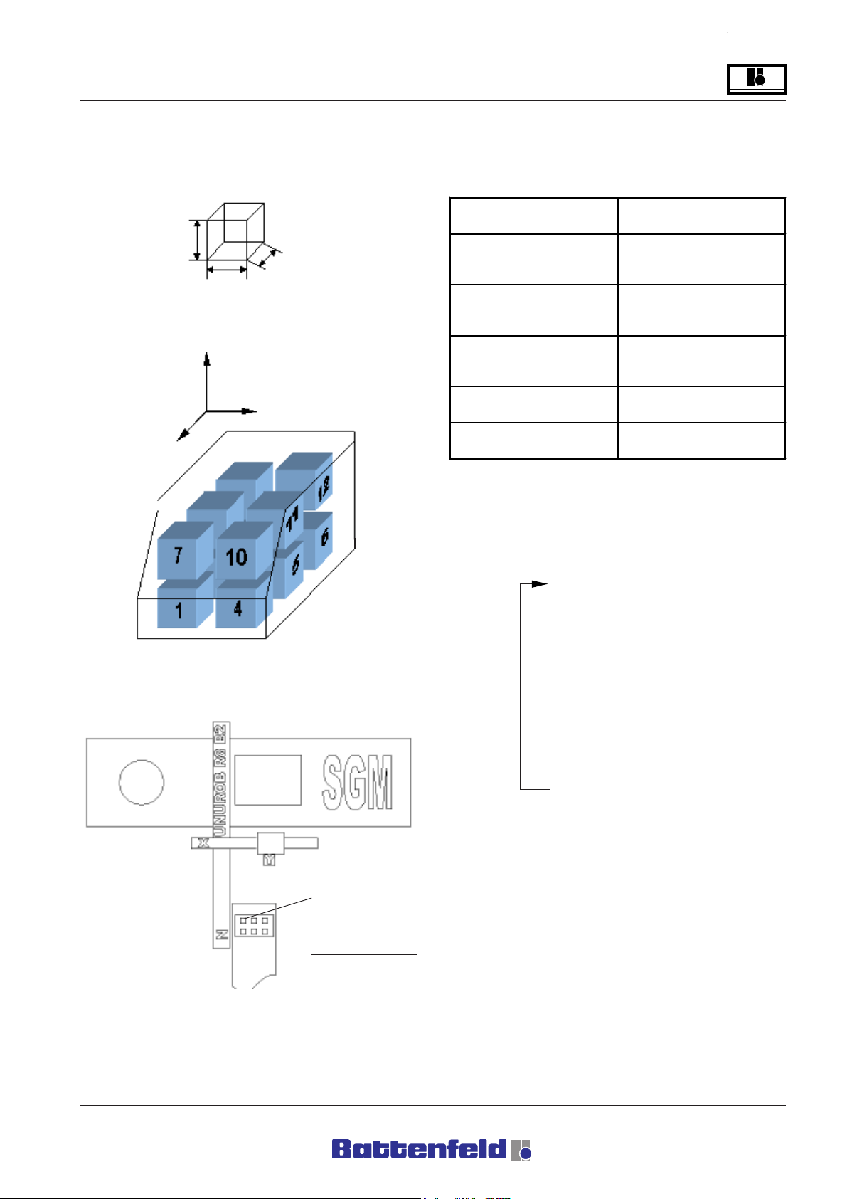
Operation and Control System
?
Palletising program entries
Example of workpiece dimensions:
50mm
50mm
50mm
Example of positioning pattern inside a crate:
Y
Z
X
The individual parameters are entered according
to this model (refer to 5.5.5.4 Palletising
program) (Palletising program entries are
explained in 5.5.5.4)
Parameter Value
X 200.00
First position
Quantity
Difference
Palletising pattern XZY
Movement sequence ZXY
Y 800.00
Z 1200.00
Qux 3
Quy 2
Quz 2
Dfx 80.00
Dfy 51.00
Dfz 70.00
R8B2_GB140.XLS
Data displayed on the PalStat page after
positioning:
Example of the crate position:
First position:
x 200.00
y 800.00
z 1200.00
Quantityx y z
1100
2200
3001
4101
5201
6010
7110
8210
9011
10 1 1 1
11 2 1 1
0000
Notes:
- All the PalStat page data for this
palletising program are displayed
together. The PalStat page only shows
the each current line.
A: R82GB0FA.PMD
B: R82DE0FA.P65
E: 080403 / T. Weiß
G: 200103 / TCS
- In palletising pattern XYZ, Z indicates the
number of already filled rows. Y shows
the number of full levels.
Section 5.5
Page 31

?
Operation and Control System
5.5.7 Lock areas
General
Lock areas are basically used to provide
sofeware-side backup for the mechanical
functions in the robot system and the injection
moulding device. The robot cannot enter these
areas.
Users are given a total of 5 lock areas, whereby
Lock area 1 is a fixed mould area. Lock area 2
is for the tool closing side and Lock area 3 for
the tool nozzle side.
Lock areas 4 and 5 can be used as required. A
lock area is fully defined by specifying the start
and end positions.
The start coordinates "-" of the lock area define
the minimum coordinate for each axis.
The end coordinates "+" of the lock area define
the maximum coordinate for each axis.
Lock area 1 (mould area) is only treated as a
lock area provided the mould is not fully open.
This lock area is deactivated by the ”Start
handling device procedure” or ”Tool at
intermediate stop” (IMM interface) signal in order
to allow the vertical axis to be inserted between
the two mould halves.
It is important to define the mould area. This is
because the ”Enable close mould” signal is not
sent to the IMM in Set-up or Automatic mode and
the robot cannot be started automatically
(”Operating area violation” fault).
An ”Operating area violation” fault occurs when
all the axes ”violate” a lock area.
Example:
Diagram showing the lock area coordinates
ALL MIN coordinates
Axis 1: 500,00 Lock area start - Axis 2:
50.00 Lock area start
Axis 3: 200.00 Lock area start
If all the "-" and "+"positions for a single lock
area of the three main axes are entered, this
produces a cube containing the lock area as
shown in the diagram.
200.00 mm
Axis 3
350.00 mm
MAX
Axis 1: 100.00 Lock area end+
Axis 2: 400.00 Lock area end+
Axis 2: 350.00 Lock area end+
Current position
Axis 1: 475,00
Axis 2: 25,00
Axis 3: 175,00
MIN
locked
area
MAX
100.00 mm
ALL MAX coordinates
Axis 1
Protection AREA
Along X-axis 50,00
Along Y-axis 50,00
Along Z-axis 50,00
MIN
50.00 mm
Axis 2
400.00 mm
MAX
MIN
500.00 mm
Section 5.5
Page 32
A: R82GB0FA.PMD
B: R82DE0FA.P65
E: 080403 / T. Weiß
G: 020304 / TCS

Operation and Control System
Specifying lock areas
Lock areas can only be specified at Password
levels 1 or 2. Lock areas 1- 5 are available to
users. Lock areas 6-10 are reserved for
Battenfeld service engineers.
Attention!
If TEACH enter mode is selected, the system
will automatically move to the selected value
when START is pressed.
Use the arrow buttons, with the
cursor positioned accordingly, to
activate/deactivate the Enable
function. This applies to all pages where Enable
can be selected.
?
R8B2_GB099.JPG
This page is used to select either TEACH or
EDIT to specify the lock areas.
Always use the F1 function button to
return to the previous display.
Always use the F4 function button to
switch displays.
Press the ROB button.
R8B2_GB100.JPG
Enable: All lock areas ON or OFF.
R8B2_GB101.JPG
Enable: ProtArea (area to be protected) ON or
OFF.
A: R82GB0FA.PMD
B: R82DE0FA.P65
E: 080403 / T. Weiß
G: 200103 / TCS
R8B2_GB098.JPG
Section 5.5
Page 33

?
Operation and Control System
R8B2_GB103.JPG
Specify the area to be protected, the gripper and
the auxiliary axes. The old values are shown on
the right.
R8B2_GB102.JPG
Enable: Selected operating area ON or OFF.
R8B2_GB105.JPG
Enter the end coordinates for the selected lock
area in this display.
R8B2_GB104.JPG
Enter the start coordinates for the selected lock
area in this display.
Section 5.5
Page 34
A: R82GB0FA.PMD
B: R82DE0FA.P65
E: 080403 / T. Weiß
G: 020304 / TCS

Operation and Control System
?
5.5.8 Error messages
All existing errors shown on the two PCS and
ncAxis (ACOPOS servo booster) error pages
can be confirmed here.
Select the Error button.
R8B2_GB106.JPG
The number of PCS errors is indicated at the
top right of the display.
ACOPOS ERROR
Error No. 4008, 4009
One of the main axes has reached the positive
or negative hardware limit switch.
Effect:
- Current axis controller is stopped
- ACOPOS servo booster indicates an
error.
To remedy:
1. Reconnect the power supply
2. Activate movement in the opposite
direction
This error may indicate that the software limit
positions have been incorrectly configured.
Error No. 5003, 5004
Reached positive or negative SW limit position.
To remedy:
Activate movement in opposite direction.
Select ”Quit all” (F1 function button) to confirm
all errors including ACOPOS errors.
R8B2_GB107.JPG
The ACOPOS error number is shown at the top
left of the display (here 4008).
Select ”Quit” (F1 function button) to confirm the
current ACOPOS error.
A: R82GB0FA.PMD
B: R82DE0FA.P65
E: 080403 / T. Weiß
G: 200103 / TCS
Section 5.5
Page 35

?
Operation and Control System
PCS ERROR
1 Emergency Stop 1 activated
Emergency stop button on MCD activated.
To remedy:
Deactivate Emergency Stop.
The error need not be confirmed. It disappears
automatically after it has been remedied.
5 Activate Emergency Stop 1x
To test the Emergency Stop button on the
manual control device (MCD) press once and
release.
6 Rob 0
The injection moulding device is set to ”Rob 0”
when it is running without the robot.
15 Pos. in TL
This error message occurs when an automatic
program is activated with the robot in the mould
area.
To remedy:
- Switch to Manual control and move the
axes out of the mould area.
- Confirm error.
52, 53 Casting Mon. 1
One of the casting monitoring devices was
activated and the required status of the casting
monitor inputs (switching status) logic ”0” and
logic ”1” is not available when the casting is
clamped. The number at the end is the number
of the clamping and vacuum circuit.
Effect (52):
- Movement stops at end of cycle (Pstop)
Effect (53):
- Current servo axis stops moving (Stop)
- Enable signals to IMM disappear.
R8B2_GB108.JPG
Use F1 to select ”Rob 1” to operate the IMM with
the robot.
To remedy 52, 53:
- Adjust the sensitivity of the limit switches
on the gripper finger.
- Adjust the sensitivity of the vacuum
monitor on the Venturi nozzle of the
suction gripper.
- Press the START button on MCD
(System continues in Automatic mode).
Section 5.5
Page 36
A: R82GB0FA.PMD
B: R82DE0FA.P65
E: 080403 / T. Weiß
G: 020304 / TCS

Operation and Control System
?
58 Axis in Bpos.
Effect:
This error message is sent out if the auxiliary
axes are not in the specified position when the
reference movement is started.
To remedy:
Switch to Manual mode and move the axes to
their basic position.
59 Compressed air monit.
Possible cause:
Compressed air dropped below 3 bar (44 psi).
Effect:
- Current servo axis stops moving.
- Enable signals to IMM disappear.
- Movement of all pneumatic axes and
gripper functions is blocked.
To remedy:
- Check compressed air.
- Press the START button on the MCD
(System continues in Automatic mode).
61 Warn.Con. full 1
Cause:
Signal indicates that the ”Warning Conveyor full”
limit switch has been reached.
Effect:
- Error message is only an instruction. It
need not be confirmed.
To remedy:
- Clear conveyor.
- Check limit switches.
62 Conv. full 1
Cause:
Conveyor was stopped by the limit switch
(conveyor stop).
Effect:
- Conveyor is stopped.
- Error need not be confirmed.
To remedy:
- Clear conveyor.
- Check limit switches.
A: R82GB0FA.PMD
B: R82DE0FA.P65
E: 080403 / T. Weiß
G: 200103 / TCS
Section 5.5
Page 37

?
Operation and Control System
120 Lock area 2
The robot has been moved into a specified lock
area by the X,Y or Z axis.
Effect:
- Current servo axis stops moving.
- IMM enable signals are cancelled if Lock
area 1 (moulding area) is affected.
To remedy:
- If an axis has been moved into a lock
area, exit the violated lock area in the
opposite direction.
- Confirm error.
123 Control parameter
Effect:
Control parameter was not loaded.
To remedy:
- Load service data (PWL 1).
- Confirm error.
124 Controller!
Effect:
One axis movement command was tarted.
Servo booster not activated or power supply not
connected.
To remedy:
- Power ON.
126 Controller error!
Effect:
Controller indicates an error. Select F4 to view
more details on the PCS ERROR page (refer to
ACOPPS errors on page 22 in Section 5)
To remedy:
- A different procedure must be used,
depending upon the ACOPOS error.
134 Battery change
The CP476 B&R 2003 controller battery must
be changed.
To remedy:
Discharge the static on the top-hat rail
and the earth connection (Do not reach
into the power pack!).
Remove the cover on the lithium battery
with a screwdriver.
Pull the removal tape to take the battery
out of the holder. Avoid short circuits by
not gripping the battery with pliers or
uninsulated pliers! Only touch the top
surfaces of the battery. It can also be
removed using insulated pliers.
Correct: Incorrect:
- Confirm error.
R8B2_160.BMP
Section 5.5
Page 38
A: R82GB0FA.PMD
B: R82DE0FA.P65
E: 080403 / T. Weiß
G: 020304 / TCS

Operation and Control System
?
Insert the new battery with the poles
correctly positioned. To do this, lift the
removal tape and insert the battery into
the compartment with the ”+” side facing
downwards. It is important to ensure that
the removal tape is on top of the battery
so that it can be removed again.
Put the overlapping end of the removal
tape under the battery to prevent it
protruding from the battery
compartment.
Mount the cover. Make sure that the
screwdriver recess is facing upwards
(1). First insert the top end of the cover
into the recess of the battery
compartment (2). Press down the cover
to lock the bottom end in place (3).
Abbreviations:
MCD Manual Control Device
SD Service door
na not available
nposs not possible
PWL Password level
TL Tool
M Main program
P Parallel program
S Subprogram
Battenfeld Customer Services
If you require any further information please
contact Battenfeld Customer Services.
R8B2_166.JPG
Note
Lithium batteries are classed as hazardous
waste! Used batteries must be disposed of
in the proper manner.
A: R82GB0FA.PMD
B: R82DE0FA.P65
E: 080403 / T. Weiß
G: 200103 / TCS
Section 5.5
Page 39

?
Operation and Control System
Section 5.5
Page 40
A: R82GB0FA.PMD
B: R82DE0FA.P65
E: 080403 / T. Weiß
G: 020304 / TCS

Operation
0
6 Operation
Taking into account the various influencing
factors we recommend that the commissioning
procedure be carried out by Battenfeld staff.
This is not only done for warranty reasons but
also for the purpose of:
• Checking the robot system for any
possible transport damage and also for
defects during installation and when
connecting it up to the power supply.
• Training operating personnel.
• Providing additional advice on operating,
maintaining and repairing the system.
6.1 Commissioning
Installation and Preparation
• It is important that you read the operating
manual and pay attention to the safety
instructions. Refer to the Section on
Safety.
Activating the main switch
All the control system components are checked
for faults during the start-up sequence. When
the control system (CP 476 central processing
unit) is ready for operation, the green RUN LED
on the controller lights up and the start-up
display appears.
If an error is detected during the start-up
sequence, the red ”ERROR” LED lights up at
the controller. The controller is not ready for
operation and therefore the display remains
blank. (refer to 5.5.2 Start-up display)
Enter your password
Your must enter your password in order to be
able to use any of the functions.
Attention!
Password level - refer to 5.5.2 Start-up
display
Test the EMERGENCY STOP slam button
on the MCD
• Unload the robot system, transport it to
the installation site and mount it on the
IMM. Refer to the Section on Transport
and Installation.
• Set up the pneumatic system. Refer to
the Section on Transport and Installation.
• Set up the electrical system. Refer to the
Section on Transport and Installation.
• Connect up the power supply
(secondary distribution).
• Check the lubrication points. Refer to the
Section on Transport and Installation
To test the Emergency Stop slam
button on the manual control
device (MCD) press once and
release. This also generates an
error message. Also check that all
the other EMERGENCY STOP
devices (IMM, peripherals) are
released.
A: R82GB0GA.PMD
B: R82DE0GA.PMD
E: 080403 / T.Wenger
G: 020403 / TCS
Section 6
Page 1

0
Operation
Press START + Totmann button on the MCD
After checking the EMERGENCY
STOP line and activating the
EMERGENCY STOP slam button
press the green ”START” button and
the ”TOTMANN” button on the MCD
simultaneously.
The main contactor then connects the power
supply to the ACOPOS servo booster. The
power is now ON! If the power supply is not
connected this generates an error message.
The ACOPOS servo booster is now ready for
operation. The motor holding brakes remain
activated. The three servo axes are not
controlled. (Axis change-over)
Confirm error
Any occurring errors, as well as potential errors,
must be remedied and confirmed before any
further movements can be carried out.
If an error occurs, this is indicated to the
operator by the red LED in the "ERROR" button.
Press the "ERROR" button to switch to the
"ERROR" page in the display.
After remedying the error, press the F1 function
button to confirm the error message or allow it
to disappear automatically. (refer to 5.5.8 Error
messages)
Section 6
Page 2
A: R82GB0GA.PMD
B: R82DE0GA.PMD
E: 080403 / T.Wenger
G: 020403 / TCS

Operation
0
6.2 Referencing
When the controller is ready for operation after
the starting sequence, ”REF” (Referencing)
appears in the top right of the display.
The green LED in the START button
begins flashing. This indicates that the
servo axes must be referenced in order
obtain an accurate zero position.
After start-up the current position of the
servo axes is assumed to be the zero point.
(Direct referencing is not recommended).
Provided none of the linear axes are in a critical
position (visual check), switch to Manual mode
(MAN appears in the display) in order to move
the axis (axes) out of the danger zone (tool,
periphery).
Press the MAN button.
Use the arrow buttons to move
the linear axes out of the danger
zone and to move the auxiliary
axes into the required end position.
It is usually only necessary to move the Y-axis to
its basic position.
The B and C (if available) auxiliary axes must
also be located in a specified end position in
order to facilitate unobstructed referencing. If this
is not the case, an error message is generated
and the referencing movement cannot be
completed (refer to 5.5.8 Error messages). This
should therefore be checked before starting the
referencing movement.
A: R82GB0GA.PMD
B: R82DE0GA.PMD
E: 080403 / T.Wenger
G: 020403 / TCS
Section 6
Page 3

0
Operation
Once all the referencing conditions have been
fulfilled, the referencing movement can begin.
Press the REF button.
The green LED in the START button
lights up.
Press the START
button and the
TOTMANN button
simultaneously.
This activates the referencing movement. First
the Y-axis moves to its reference point in a ” - direction”. Once the Y-axis has been calibrated
(stationary), the horizontal axes (X, Z) move
towards their reference points.
It is now possible to start the token programs
and Teach functions.
When moving servo axes which have not
been referenced it is important to note that
the paths of the main axes are not defined.
This means that the robot can move up to
the hardware limit switches, where it is
automatically stopped by the movement of
the ACOPOS servo control, which generates
an error message at the pos./neg. HW limit
switch.
When all three linear axes have reached their
reference positions, ”HOME” appears at the top
right of the display and the controller
automatically switches to Manual mode (LED in
button lights up).
Section 6
Page 4
A: R82GB0GA.PMD
B: R82DE0GA.PMD
E: 080403 / T.Wenger
G: 020403 / TCS

Operation
0
6.3 Manual operation
Press MAN switch the robot to
Manual mode.
Use the arrow buttons (+,-) to
move the linear and the auxiliary
axes according to the cursor
position on the Axis status page. (Page
selection is explained in Section 5.5.3 Status
pages).
Axis status display:
The override function
is adjusted in 5%
increments (Minimum
value = 5%, Maximum value = 100%) using the
two buttons (snail, hare) to the left and right of
the arrow buttons.
Override values can also be entered using the
numerical pad on the Axis status page.
Manual mode speeds
In unreferenced mode the linear axes move at
5% of the Override setting depending upon the
maximum speed.
In referenced mode the linear axes move at 10%
of the Override setting depending upon the
maximum speed.
R8B2_GB053.JPG
A: R82GB0GA.PMD
B: R82DE0GA.PMD
E: 080403 / T.Wenger
G: 020403 / TCS
Section 6
Page 5

0
Operation
6.4 Single step mode
In Single step mode each of the program lines is
implemented after pressing the START and the
TOTMANN buttons simultaneously (Automatic
mode - Individual steps).
If the Automatic program is new or been
modified it is advisable to test it in Single step
mode before allowing the sequence to start fully
automatically. This makes it possible to detect
and remedy any programming errors or
incorrectly entered data in advance.
Press the AUTO/SINGLE button twice
to activate Single step mode.
”AUTO” appears at the top right of the display
after the button has been pressed once.
This is replaced by ”SINGLE” after the button
has been pressed again.
Press the TOTMANN button
and the START button.
to start the program sequence.
The token program sequence is carried out line
by line, i.e. it is interrupted at the end of each
program line. Press the START button again to
continue. The control system switches to STOP
at the end of each line and waits for the next
Start command.
Press the START button again to move
to the next line in the token program. This
enables you to control the program
sequence before switching over to Fully
Automatic mode. This function is especially
important for executing movement commands.
The green LED in the START button then
begins flashing.
Any program errors detected during the step
movement sequence can be corrected using
the program Editor. (refer to 5.5.5 Creating token
programs)
The override function
is adjusted in 5%
increments (Minimum
value = 5%, Maximum value = 100%) using the
two buttons (snail, hare) to the left and right of
the arrow buttons.
Section 6
Page 6
A: R82GB0GA.PMD
B: R82DE0GA.PMD
E: 080403 / T.Wenger
G: 020403 / TCS

Operation
0
Status displays:
R8B2_GB114.JPG
The current axis positions can be read off the
Axis status page during Single step mode. (refer
to Section 5.5.3 Status pages)
Press the F4 function button (=continue) to read
off the current program status. Press the START
button to execute the command in the marked
program line.
R8B2_GB115.JPG
Exiting Single step mode:
Press the MAN button to switch to Manual mode.
Press the ”AUTO/SINGLE” button to switch to
Automatic mode. (refer to 5.5.5 Creating token
programs)
A: R82GB0GA.PMD
B: R82DE0GA.PMD
E: 080403 / T.Wenger
G: 020403 / TCS
Section 6
Page 7

0
Operation
6.5 Automatic mode
Once the Automatic program has been
adequately tested in Single step mode, you can
start the token program for Fully Automatic
operation.
Automatic mode must be started outside of the
danger zones. (e.g. in the mould area)
Press the AUTO/SINGLE button.
Activate the START button.
Press the TOTMANN button
and the
Status displays:
The status displays are used in the same way
as in Single step mode. (refer to 6.4)
Automatic mode speeds
In Automatic mode the linear axes are operated
according to the Override function setting (5% 100%).
The override function
is adjusted in 5%
increments (Minimum
value = 5%, Maximum value = 100%) using the
two buttons (snail, hare) to the left and right of
the arrow buttons.
Override values can also be entered using the
numerical pad on the Axis status page.
(Minimum value = 5%, Maximum value = 100%).
START button to start the program
sequence.
The program sequence automatically runs to
the end of the program or until it is interrupted by
the user.
Exiting Automatic mode:
Press the MAN button to switch to
Manual mode.
Press the AUTO/SINGLE button to
switch to Single step mode. (refer to
5.5.5 Creating token programs).
Section 6
Page 8
A: R82GB0GA.PMD
B: R82DE0GA.PMD
E: 080403 / T.Wenger
G: 020403 / TCS
 Loading...