


Specification
Available from Midas Components LTD
Telephone Number: +44(0) 1493 602602
Website: www.midascomponents.co.uk
Email: sales@midascomponents.co.uk
COG-BT96040A-03
Doc. No.: VL-FS-COG-BT96040A-03 REV.A
Version March 2007
Data Modul AG - www.data-modul.com
DOCUMENT REVISION HISTORY
DOCUMENT
DATE DESCRIPTION CHANGED
REVISION
FROM TO
A 2007.03.23 First Release.
Based on
a.) Test Specification:
VL-TS-COG-BT96040A-XX REV.A
2007.02.08
b.) VL-QUA-012B REV.W 2004.03.20
According to VL-QUA-012B, LCD size
is small because Unit Per Laminate=28
which is more than 6pcs/Laminate.
BY
LINDA
ZHU
CHECKED
BY
VIVIAN
LUO
Data Modul AG - www.data-modul.com
2
CONTENTS
Page No.
1. GENERAL DESCRIPTION 4
2. MECHANICAL SPECIFICATIONS 4
3. INTERFACE SIGNALS 6
4. ABSOLUTE MAXIMUM RATINGS 7
4.1 ELECTRICAL MAXIMUM RATINGS –FOR IC ONLY 7
4.2 ENVIRONMENTAL CONDITION 7
5. ELECTRICAL SPECIFICATIONS 8
5.1 TYPICAL ELECTRICAL CHARACTERISTICS 8
5.2 TIMING SPECIFICATIONS 9
5.3 POWER ON/OFF TIMING DIAGRAM 11
6. LCD SPECIFICATIONS 13
7. LCD_COSMETIC_CONDITIONS 21
Data Modul AG - www.data-modul.com
3
Specification
of
LCD Module Type
Item No.: COG-BT96040A-03
1. General Description
z 96 x 40 dots STN Yellow Positive Reflective Dot Matrix LCD module.
z Viewing angle: 12 O’clock.
z Driving scheme: 1/49 duty, 1/8 bias.
z Driving IC: ‘ST’ STE2004S (COG form) LCD controller/driver or equivalent.
z Logic voltage: 3V.
z “RoHS” compliance.
2. Mechanical Specifications
The mechanical detail is shown in Fig. 1 and summarized in Table 1 below.
Table 1
Parameter Specifications Unit
Outline dimensions 46.0(W) x 36.2(H) x 1.98(D) (Excluded pins and EPOXY) mm
Viewing area 40.0(W) x 23.0(H) mm
Active area 35.217(W) x 18.225(H) mm
Display format 96 x 40 dots
Dot size 0.352(W) x 0.441(H) mm
Dot spacing 0.015(W) x 0.015(H) mm
Dot pitch 0.367 (W) x 0.456(H) mm
Weight: Approx: 6.5 gram
Data Modul AG - www.data-modul.com
4
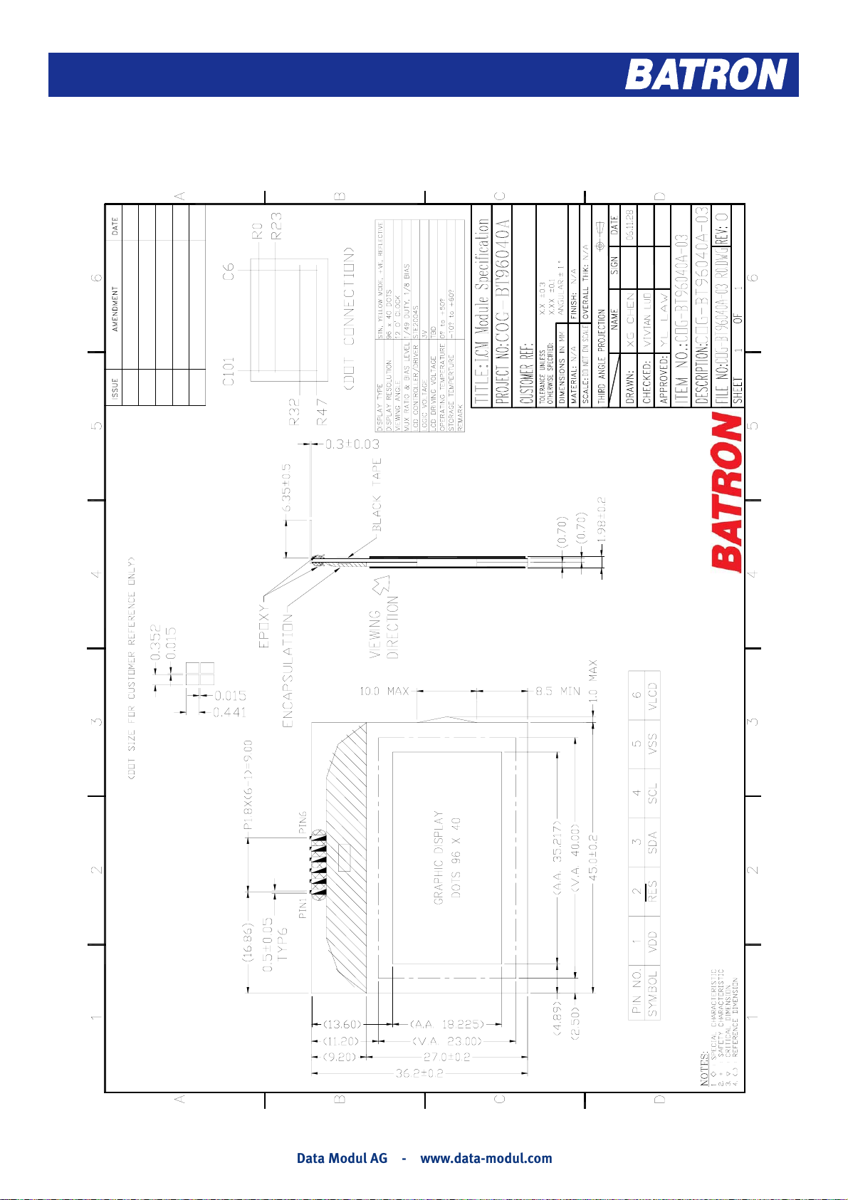
Figure 1: Module Specification
Data Modul AG - www.data-modul.com
5
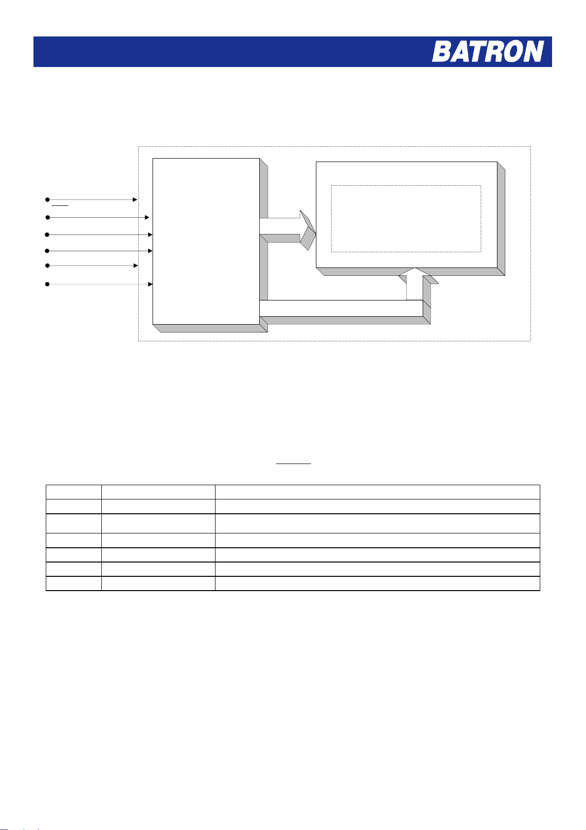
VDD
RES
SDA
SCL
VSS
VLCD
3. Interface signals
'ST'
STE2004S
(COG)
LCD CONTROLLER/
DRIVER OR
EQUIVALENT
Figure 2: Block Diagram
40
Table 2
COG-BT96040A-03
96 X 40 DOTS
96
Pin No. Symbol Description
1 VDD Power supply for logic (+3V).
2
_______
RES
Reset Input. Active Low.
3 SDA I2C Bus Data Out IF UNUSED MUST BE LEFT FLOATING.
4 SCL I2C bus Clock - CANNOT BE LEFT FLOATING.
5 VSS Ground (0V).
6 VLCD Power supply for LCD driver.
Data Modul AG - www.data-modul.com
6
4. Absolute Maximum Ratings
A
H
V
r
H
4.1 Electrical Maximum Ratings-For IC Only
Table 3
Parameter Symbol Min. Max. Unit
Power Supply voltage VDD(=VDD1=VDD2) -0.5 +5.0 V
Input voltage (all input pads) Vin -0.5 VDD1+0.5 V
Power Supply voltage (LCD drive) VLCD -0.5 +15.0 V
Note:
The modules may be destroyed if they are used beyond the absolute maximum ratings.
All voltage values are referenced to VSS = 0V.
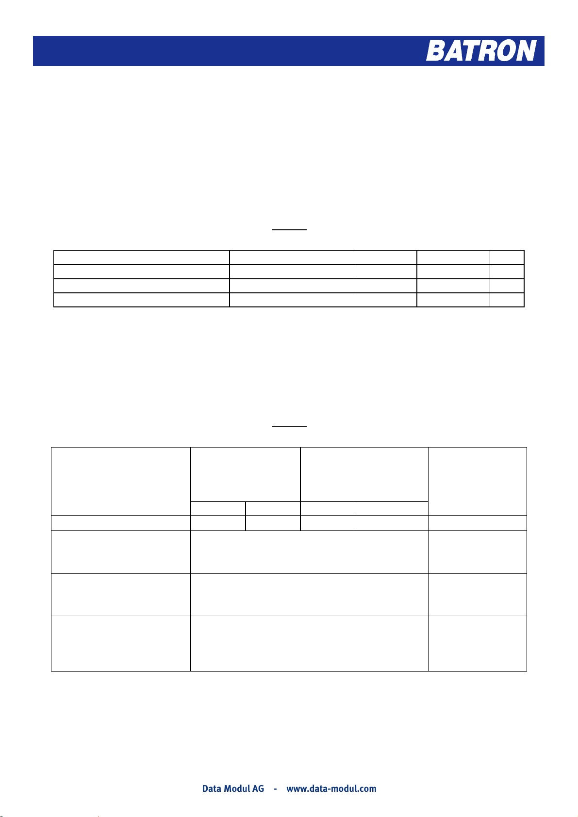
4.2 Environmental Condition
Table 4
Item
Operating
Temperature
(Topr)
Storage
Temperature
(Tstg)
(Note 1)
Min. Max. Min. Max.
mbient Temperature
0qC +50qC -10qC +60qC
90% max. RH for Ta 40qC
umidity (Note 1)
<50%RH for 40qC <Ta Maximum operating
temperature
ibration (IEC 68-2-6)
cells must be mounted on a
suitable connecto
Frequency: 10 a 55 Hz
Amplitude: 0.75 mm
Duration: 20 cycles in each direction.
Pulse duration: 11 ms
Shock (IEC 68-2-27)
alf-sine pulse shape
Peak acceleration: 981 m/s
Number of shocks: 3 shocks in 3 mutually
2
= 100g
perpendicular axes.
Note 1: Product cannot sustain at extreme storage conditions for long time.
Remark
Dry
No condensation
3 directions
3 directions
Data Modul AG - www.data-modul.com
7

5. Electrical Specifications
5.1 Typical Electrical Characteristics
At Ta = 25 qC, VDD =VDD1=VDD2= +3.0Vr5%, VSS=0V.
Table 5
Parameter Symbol Conditions Min. Typ. Max. Unit
Supply voltage
(Logic)
Supply voltage
(LCD) (built-in)
VDD-VSS
VLCD-VSS
Ta=0 qC,
VDD =3V, Note 1
Ta=+25 qC,
VDD =3V, Note 1
Ta=+50 qC,
VDD =3V, Note 1
2.85 3.0 3.1 5 V
9.71 10.22 10.73 V
9.63 10.11 10.58 V
9.35 9.85 10.34 V
Logic HIGH
Voltage Level
Logic LOW
voltage level
Supply Current
(Logic & LCD)
V
IH
V
IL
IDD
Note 1, VDD = 3V,
Character mode
Note 1, VDD = 3V,
Checker board mode
0.7 VDD1 - VDD2 V
VSS - 0.3 VDD1 V
- 0.3 0.45 mA
- 0.5 0.75 mA
Note 1: There is tolerance in optimum LCD driving voltage during production and it will be within the
specified range.
Data Modul AG - www.data-modul.com
8

5.2 Timing Specifications
Reset Timing
Ta = 0 qC to +50 qC, VDD =VDD1=VDD2= +3.0Vr5%, VSS=0V;
Table 6
Figure 3: Reset Timing Diagram
Data Modul AG - www.data-modul.com
9

I2C BUS INTERFACE
Ta = 0 qC to +50 qC, VDD =VDD1=VDD2= +3.0Vr5%, VSS=0V;
Table 7
SDA
SCL
f
=
osc
960
Notes: 1.
F
frame
2. All timing values are valid within the operating supply voltage and ambient temperature ranges and referenced
to V
and VIH with an input voltage swing of VSS to V
IL
3. Cb is the capacitive load for each bus line.
4. For bus line loads Cb between 100 and 400pF the timing parameters must be linearly interpolated
5. C
is the filtering CApacitor on VLCD
VLCD
6. Trise and Tfall (30%-70%) -10ns
2
7. I
C bus AC Characteristics are tested by correlation
Figure 4: I2C bus timing diagram
DD.
Data Modul AG - www.data-modul.com
10

5.3 Power on/off timing diagram
1) Power on timing diagram
Data Modul AG - www.data-modul.com
11

2) Power off timing diagram
Data Modul AG - www.data-modul.com
12

6. LCD Specifications
Figure 5: LCD drawing 1
Data Modul AG - www.data-modul.com
13

Figure 6: LCD drawing 2
Data Modul AG - www.data-modul.com
14

Figure 7: LCD drawing 3
Data Modul AG - www.data-modul.com
15

Figure 8: LCD drawing 4
Data Modul AG - www.data-modul.com
16

Figure 9: LCD drawing 5
Data Modul AG - www.data-modul.com
17

Figure 10: LCD drawing 6
Data Modul AG - www.data-modul.com
18

Figure 11: LCD drawing 7
Data Modul AG - www.data-modul.com
19

Figure 12: LCD drawing 8
Data Modul AG - www.data-modul.com
20

8. LCD Cosmetic Conditions
a.) Reference document follow VL-QUA-012B.
b.) LCD size of the product is small.
- END -
Data Modul AG - www.data-modul.com
21

Data Modul Headquarters Munich
Landsberger-Str. 322
D-80687 Munich - Germany
Tel.: +49-89-56017-0
Sales Office Berlin
berlin@data-modul.com
Germany
Tel.: +49-033397/67909
Sales Office Duesseldorf
Fritz-Vomfelde-Str. 8
40547 Duesseldorf - Germany
Tel.: +49-211-52709-0
Sales Office Stuttgart
Friedrich-List-Str. 42
70771 Leinfelden-Echterdingen
Germany
Tel.: +49-711-782385-0
Data Modul France, S.A.R.L.
Bat B - Hall 204
1-3 Rue des Campanules
77185 Lognes - France
Tel.: +33-1-60378100
Data Modul Italia, S.r.l.
Regus Center Senigallia
Via Senigallia 18/2
20161 Milano - Italy
Tel.: +39-02-64672-509
Data Modul Iberia, S.L.
c/ Adolfo Pérez Esquivel 3
Edificio Las Americas III Oficiana 40
28230 Parque Empresarial
Madrid Las Rozas - Spain
Tel.: +34-609 61 80 40
Data Modul Ltd. / UK
3 Brindley Place
Birmingham B 12JB
United Kingdom
Tel.: +44-121-698-8641
Data Modul Inc. / USA
1767-46 Veterans Memorial Highway
Islandia NY 11749
USA
Tel.: +1-877-951-0800
www.data-modul.com
display@data-modul.com
 Loading...