

36 8 mm Character Height LCD Modules - MACRO LINE
BATRON
Character
LCD Modules
■ BLOCK DIAGRAM
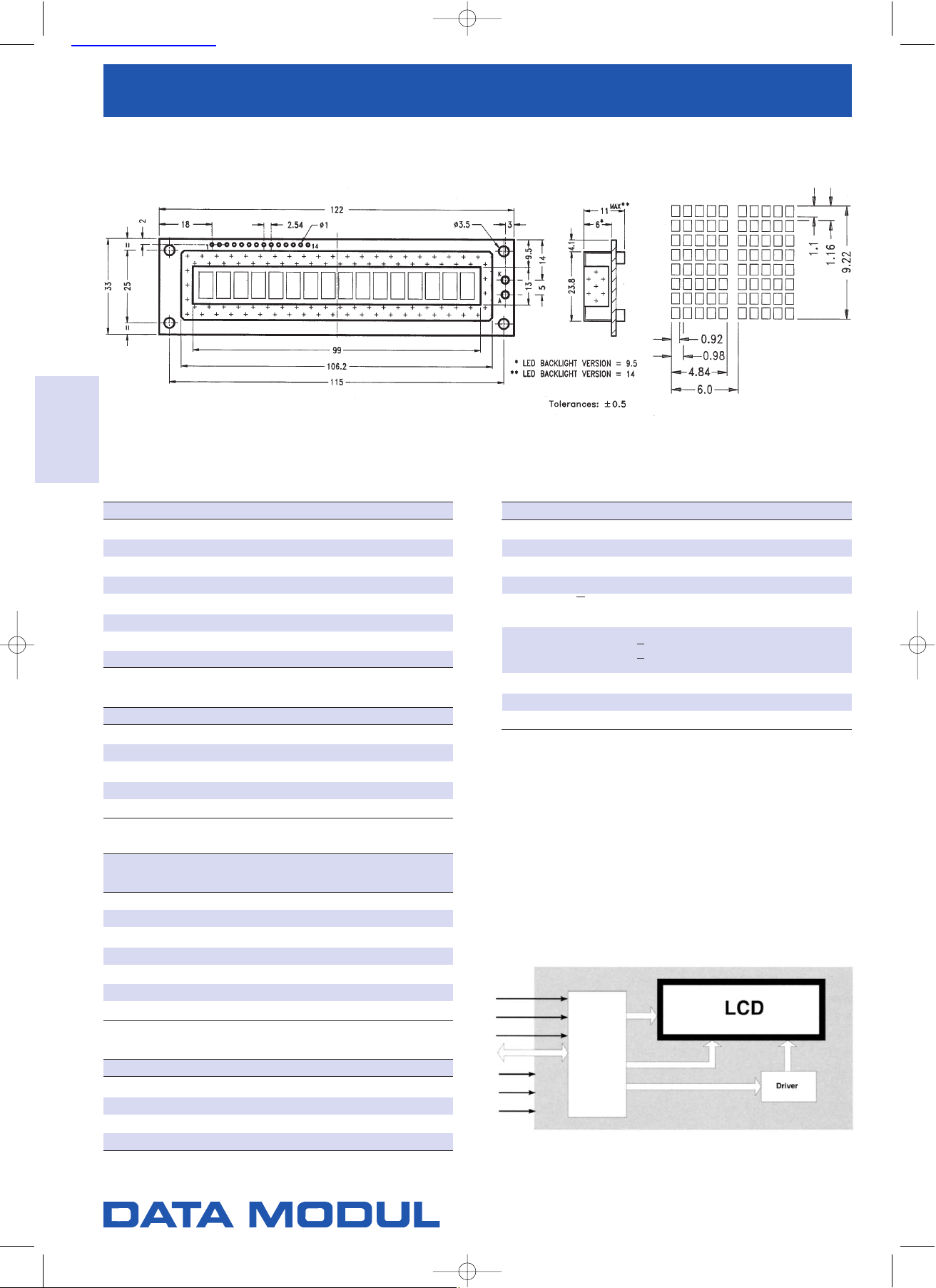
■ MECHANICAL DATA
Parameter Width x Height x Depth Unit
Outline Dimensions 122 x 33 x 11 (with LED: 14) mm
Effective viewing area 99 x 13 mm
Dot Size 9.2 x 1.1 mm
Dot Pitch 0.98 x 1.16 mm
Character Matrix 5 x 7 dots
Character Size 4.84 x 8.06 mm
Character Pitch 6.0 mm
Weight Approximate 50 (with LED: 55) g
■ ABSOLUTE MAXIMUM RATINGS
Parameter Symbol Min. Max. Unit
Supply Voltage (Logic) VDD(VDD-VSS) 0 7.0 V
Supply Voltage (LCD Driver) VEE(VDD-V0) 0 13.5 V
Input Voltage V
I
V
SS
V
DD
V
Operating Temperature T
OP
See Page 11 °C
Storage Temperature T
ST
See Page 11 °C
■ ELECTRICAL CHARACTERISTICS
Condition: Ta = 25°C, VDD= 5.0
± 0.25
V
Parameter Symbol Min. Typ Max. Unit
Input Voltage HIGH V
INH
2.2 --- --- V
Input Voltage LOW V
INL
--- --- 0.6 V
Output Voltage HIGH V
OH 2.4 --- --- V
Output Voltage LOW V
OL --- --- 0.4 V
Supply Current (Logic) I
DD
--- 1.0 --- mA
Supply Current (LCD Driver) I
0
--- 0.5 --- mA
Duty Ratio --- --- 1 / 8 --- ---
■ LED BACKLIGHT (STANDARD COLOR GREEN)
Parameter Symbol Min. Typ Max. Unit
Supply Voltage V
F
3.8 4.0 4.2 V
Supply Current IF[at 25°C] --- 160 240 mA
Lamp Style --- --- 04 --- ---
LED Segments --- --- 16 --- pcs
■ PIN TABLE
Pin Symbol Signal Description
1VSSGND (0 V)
2VDDPower Supply (5 V)
3V0Supply Voltage (LCD Driver)
4 RS Register Select - LOW = Instruction, High = Data
5 R / W Read / Write
LOW = MPU to LCM, HIGH = LCM to MPU
Enable
6 E R / W = LOW: Data are taking over at falling edge of E
R / W = HIGH: Data can be read at E = 1
7 to 14 DB0to DB7Data Bus - Software selectable 4 or 8 Bit Mode
A+V
LED
Anode of LED Unit
K-V
LED
Cathode of LED Unit
■ ADDITIONAL INFORMATION
◆ Display Connector Type - without LED: 1 x 14
◆ Display Connector Type - with LED: See Drawing
◆ Controller Type - SPLC 780 (1) or compatible
BT 11608
1 Line x 16 Characters
Dot Size
Dimensions [mm]
Controller
Data Modul AG - Landsberger Str. 322 - 80687 München - Tel. 089-56017-0 - Fax 089-56017-119 –
www.data-modul.de
查询BT11608供应商
 Loading...