

Page 1

IMPORTANT SAFETY INSTRUCTIONS
READ AND FOLLOW ALL INSTRUCTIONS
Owner’s
Use and Care Guide for
Hydromassage Baths
With
Installation
Instructions
SAVE THESE INSTRUCTIONS
Page 2

INTRODUCTION
Thank You for choosing us. The perfect tub
for your remodeling and building needs.
Before Using
Before using your Hydromassage Bath Tub, please read the IMPORTANT
OPERATING, SAFETY, MAINTENANCE, and INSTALLATION INSTRUCTIONS
in this manual. To ensure maximum performance and warranty protection, be
sure your bath unit is installed according to the installation instructions in this
manual.
ALSO NOTE
INSTALLATION OF HYDROMASSAGES MUST CONFORM TO STATE
AND LOCAL CODES: BUILDING, PLUMBING, AND ELECTRICAL.
Electrical component manufacturers instructions for bonding and
grounding are especially important and must be in compliance.
The variety of installations possible with this Hydromassage tub may
require framing procedures other than those described in this manual.
Information contained in this manual is based on the latest product features
available at the time of publication. We reserve the right to make changes in
product features, packaging or availability without notice. Our hydromassage
tubs are UL listed.
TABLE OF CONTENTS
Introduction . . . . . . . . . . . . . . . . . . . . . . . . . . . . . . . . . . . . . . . . . . . . . . . . . . . .1
Table of Contents . . . . . . . . . . . . . . . . . . . . . . . . . . . . . . . . . . . . . . . . . . . . . . .1
Important Safety Instructions . . . . . . . . . . . . . . . . . . . . . . . . . . . . . . . . . . . . .2
Framing Tub/Shower Units . . . . . . . . . . . . . . . . . . . . . . . . . . . . . . . . . . . . . .3, 4
Framing Sunken Units . . . . . . . . . . . . . . . . . . . . . . . . . . . . . . . . . . . . . . . . . . .5
Apron Installation . . . . . . . . . . . . . . . . . . . . . . . . . . . . . . . . . . . . . . . . . . . . . . .6
Electrical Connections . . . . . . . . . . . . . . . . . . . . . . . . . . . . . . . . . . . . . . . . . . .6
Operating Instructions . . . . . . . . . . . . . . . . . . . . . . . . . . . . . . . . . . . . . . . . . . .7
Pictorial Example . . . . . . . . . . . . . . . . . . . . . . . . . . . . . . . . . . . . . . . . . . . . . . . .7
Care and Cleaning . . . . . . . . . . . . . . . . . . . . . . . . . . . . . . . . . . . . . . . . . . . . . . .8
Limited Warranty . . . . . . . . . . . . . . . . . . . . . . . . . . . . . . . . . . . . . . . . . . . . . . . .9
Troubleshooting Guide . . . . . . . . . . . . . . . . . . . . . . . . . . . . . . . . . . . . . . . . . .10
1
Page 3

IMPORTANT SAFETY INSTRUCTIONS
INSTRUCTIONS PERTAINING TO A RISK OF FIRE
ELECTRIC SHOCK, OR INJURY TO PERSONS.
IMPORTANT SAFETY INSTRUCTIONS
WARNING–When using this unit, basic precautions should always be followed,
including the following:
1. READ AND FOLLOW ALL INSTRUCTIONS.
2. DANGER: To reduce the risk of injury, do not permit children to use this unit
unless they are closely supervised at all times.
3. The water temperature in the hydromassage bath should not exceed 104
degrees F (40 deg C). Hot hydromassage baths can put certain stresses on the
body, as does any hot bath or shower. Therefore, hydromassage bathing may
not be suitable for all persons. If you have a heart condition, high blood
pressure, diabetes, circulatory problems, or if you are under the care of a
physician, consult your physician before using a hydromassage bath. Failure to
do so may result in bodily injury or serious health hazards.
4. If you are pregnant you should consult your physician before using the
hydromassage bath. The hydromassage action may prove hazardous.
5. Do not consume alcoholic beverages or take medications or drugs prior to or
when using the hydromassage bath. Alcohol and drugs affect mental judgement
and inhibit bodily functions such as heartbeat and respiration, resulting in
potentially dangerous effects.
6. Acrylic and gel surfaces can be slippery when wet. Please exercise caution
when entering, leaving, or moving about in the hydromassage bath.
7. Use this unit only for its intended use as described in this manual. Do not use
attachments not recommended by the manufacturer.
8. Never drop or insert any object into any opening.
9. Do not operate this unit without the guard over the suction fitting.
10. The unit must be connected only to a supply circuit that is protected by a
ground-fault circuit-interrupter (GFCI). Such a GFCI should be provided by the
installer and should be tested on a routine basis. To test the GFCI push the test
button. The GFCI should interrupt power. Push the test button. Power should be
restored. If the GFCI fails to operate in this manner, the GFCI is defective. If the
GFCI interrupts power to the bathtub without the test button being pushed, a
ground current is flowing, indicating the possibility on an electric shock. Do not
use this hydromassage bathtub. Disconnect the hydromassage bathtub and
have the problem corrected by a qualified service representative before using.
11. (For permanently connected units) a green-colored terminal (or a wire connector
marked “G,” “GR,” “Ground,” or “Grounding.”) is provided within the terminal
compartment. To reduce the risk of electric shock the grounding terminal of your
electric service or supply panel should be wired with a conductor equivalent in
size to the circuit conductors supplying this equipment.
12. SAVE THESE INSTRUCTIONS
2
Page 4
INSTALLATION INSTRUCTIONS
ATTENTION INSTALLER: PLEASE READ THE FOLLOWING IMPORTANT
CONSIDERATIONS! READ ALL INSTRUCTIONS CAREFULLY AND FOLLOW
ALL LOCAL PLUMBING AND ELECTRICAL CODES.
1. Before installation, make sure proper access is made to the final connections.
2. Installation must comply with local and national electrical codes.
Electrical connections should be made by a qualified electrician.
3. A properly connected ground fault interrupter must be used.
4. The building materials and wiring should be routed away from the pump body or
other heat-producing components of the units.
DO NOT USE THE PIPING OR PUMP FOR STRUCTURAL SUPPORT OR POSITIONING
OF HYDROMASSAGES. DO NOT SUPPORT THE WEIGHT OF THE BATH TUB BY THE
RIM. MAKE SURE BOTH CONNECTIONS TO THE PUMP ARE SECURELY TIGHTENED.
CONSTRUCTION DAMAGE IS NOT COVERED UNDER WARRANTY!
When cleaning up after installation, DO NOT USE ABRASIVE CLEANERS as they
may scratch and dull the unit surface. Use warm water and one of the liquid
detergents to clean the surface. Stubborn stains, paint, or tar can be removed with
turpentine or paint thinner, DO NOT ALLOW CLEANERS CONTAINING
PETROLEUM DISTILLATES TO REMAIN IN CONTACT WITH TUB SURFACES FOR
LONG PERIODS OF TIME. Plaster can be removed by scraping with a wood edge.
Do not use metal scrapers, wire brushes, or other metal tools.
FRAMING TUB/SHOWER UNITS
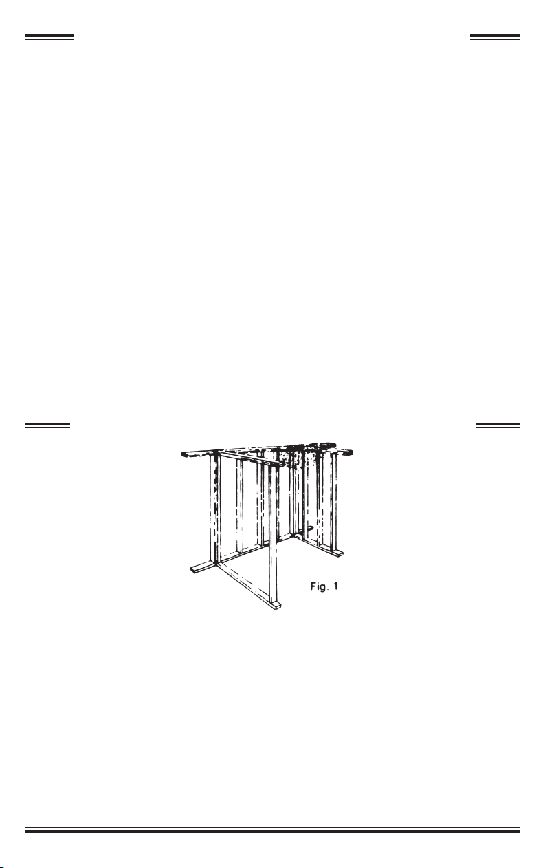
1. The tub should be on the job site during the early stage of framing. Studs may be
temporarily omitted to allow unit to be moved into place (figure1).
2. Rough-in drains should be located according to the line drawings for the particular
unit. When measuring the tub to obtain these measurements, be sure to use the
top of the unit for the overall depth and width of the unit. Please note that most
units have slanted backs and sides, but the front of the unit should always be
installed vertically plumb.
3. Prior to installation, check to be sure the framed-in area is proper size, square and
plumb.
4. If a one hour fire wall is required, contact the factory for recommended method of
installation. A one hour fire wall can normally be obtained by placing 5/8” dry wall
on the studs prior to the installation of the unit.
3
Page 5
5. A code approved drain outlet should be used. Be sure to use a non-hardening
mastic, such as Permagum, between the chrome flange and the finished side of
the tub/shower.
6. On the back of the unit, lay out accurately the location of the holes for supply and
mixing valves. Shower head may be located either through wall of unit or in wall
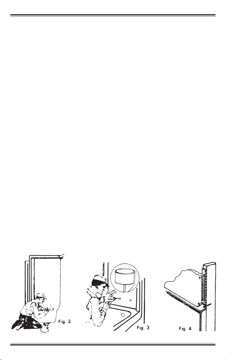
above. From the back of the unit, drill a pilot hole (1/4” or less) at location
markings for fittings (Figure 2). From the face of unit, drill or cut these holes to
required size. Use a hole saw bit of the proper size tipping the unit toward the
installer and push until the waste pipe is directly under the drain outlet, then tip
the shower upright into the framed area.
7. After unit is positioned into framed area, check level of tub/shower and be sure
apron is down tight to the floor.
8. Spot secure the flanges, top and bottom, while continuously checking to see that
the unit is level and that the side walls are plumb.
9. Using No. 8 screws, fasten the top flanges to each stud and then fasten the side
flanges approximately 8” on center or apart.
10. Install plumbing hardware in keeping with good plumbing practice and in
compliance to local code requirements.
11. To assure a watertight integrity and give additional rigidity to wall sections, place
wooden blocks against the walls of the unit and nail to the studs around valves,
shower head, and wall areas that need strengthening. Do not force walls inward.
12. If dry wall finish is to be used, place drywall over fastening flange, nail drywall and
tub flange into studs, mud tape and finish. If plaster is used, nail lath over
fastening flange and finish plaster to bead (Figure 4)
13. Towel bars and special grab bars may be bolted or screwed into the tub unit, with
the use of a wood strip or block on the back side of the unit prior to installation.
Care should be taken when installing grab bars so that all applicable codes and
requirements are followed.
14. For pump access, a 17” high by 27” wide minimum opening is needed to the
integral pump.
4
Page 6
FRAMING SUNKEN UNITS
1. Construct a framing pocket which allows for the insertion of your particular model.
(Check all dimensions against the unit to be installed.) For pump access. A 17” high
by 27” wide minimum opening is needed to the integral pump. Then install the
supply and drain piping and connecting fittings for the unit.
2. After the framing pocket is completed, insert the unit to check the fit and to be sure
the unit is level and true.
3. With a pencil, trace a mark all around the rim where it contacts the top surface of
the framing pocket.
4. Remove the unit from the framing pocket.
5. Apply a bead of adhesive sealant to the top surface of the framing pocket along
the inside edge of the mark traced around the edge of the rim.
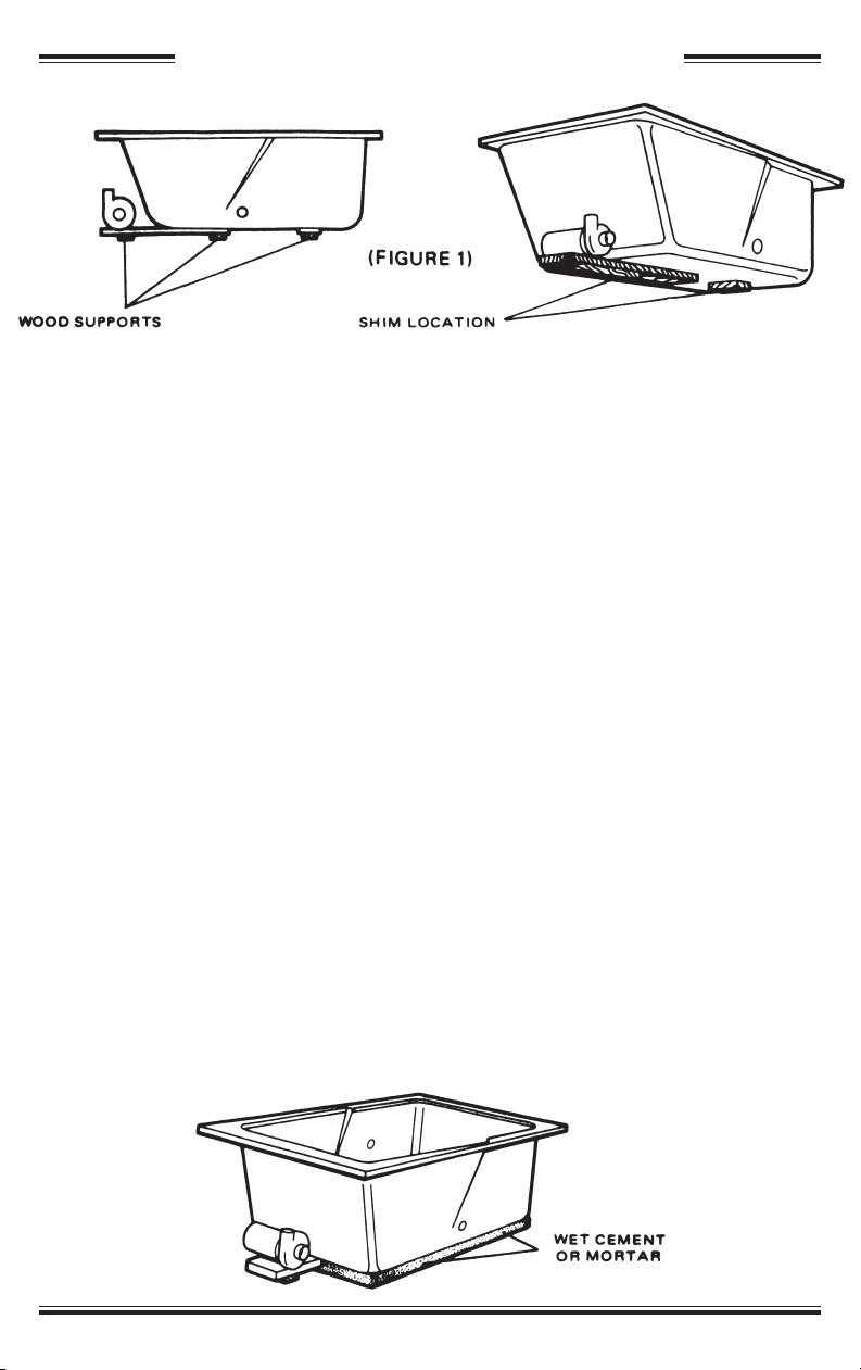
6. Hang the unit by the rim into the wet adhesive sealant, then support the floor as
shown in figure1.
CAUTION: DO NOT SUPPORT BATH TUB ON RIM. PROVIDE SUPPORT UNDER
BLOCKS ON UNDERSIDE OF HYDROMASSAGE.
7. Connect the supply and drain connections, then fill the unit half full of water and
allow to stand overnight.
These are two methods of supporting the bottom of your the Manufacturer unit:
1. After the unit is installed in the framing pocket, cut shims from framing material and
position as indicated above.
2. The unit can be set on a “donut” or ring of wet cement or mortar as shown below.
The cement or mortar must be put in place before the unit is installed in the framing
pocket then insert the unit while the cement is still soft so that the cement is tight
against the bottom for support.
5
Page 7

ELECTRICAL CONNECTIONS
WARNING – When using electrical products, basic precautions should always
be followed, including the following:
A licensed electrician should make all service connections.
1. DANGER RISK OF ELECTRIC SHOCK. Connect only to a circuit protected by a
ground-fault circuit-interrupter.
CAUTION: All installations must have a Class A Ground-Fault Circuit Interrupter
(GFCI) which will provide additional protection against line-to-ground shock
hazard. A 120 V, 15 A, 60 Hz separate circuit is required.
2. Grounding is required. The unit should be installed by a qualified service
representative and grounded.
CAUTION: Provide a separate equipment grounding conductor for the green
Hydromassage ground wire. Ground MUST NOT be connected to any current carrying
conductor except at the main service breaker box (per National Electrical Code Article
250-61-b). A 120 V, 15 A separate circuit is required.
3. Check to make sure that the actuator tube and bleeder tee from the power panel is
attached to the air control.
4. (For built-in and custom units) Install to permit access for servicing.
6
Page 8
OPERATING INSTRUCTIONS
CAUTION: READ IMPORTANT SAFETY INSTRUCTIONS FIRST.
1. Fill unit with a water level of 2” to 3” (5 to 7.5 cm) above the highest jets (100˚F
or less recommended).
NOTE: Failure to fill water to proper level before operating your unit may
damage the pump and void the warranty.
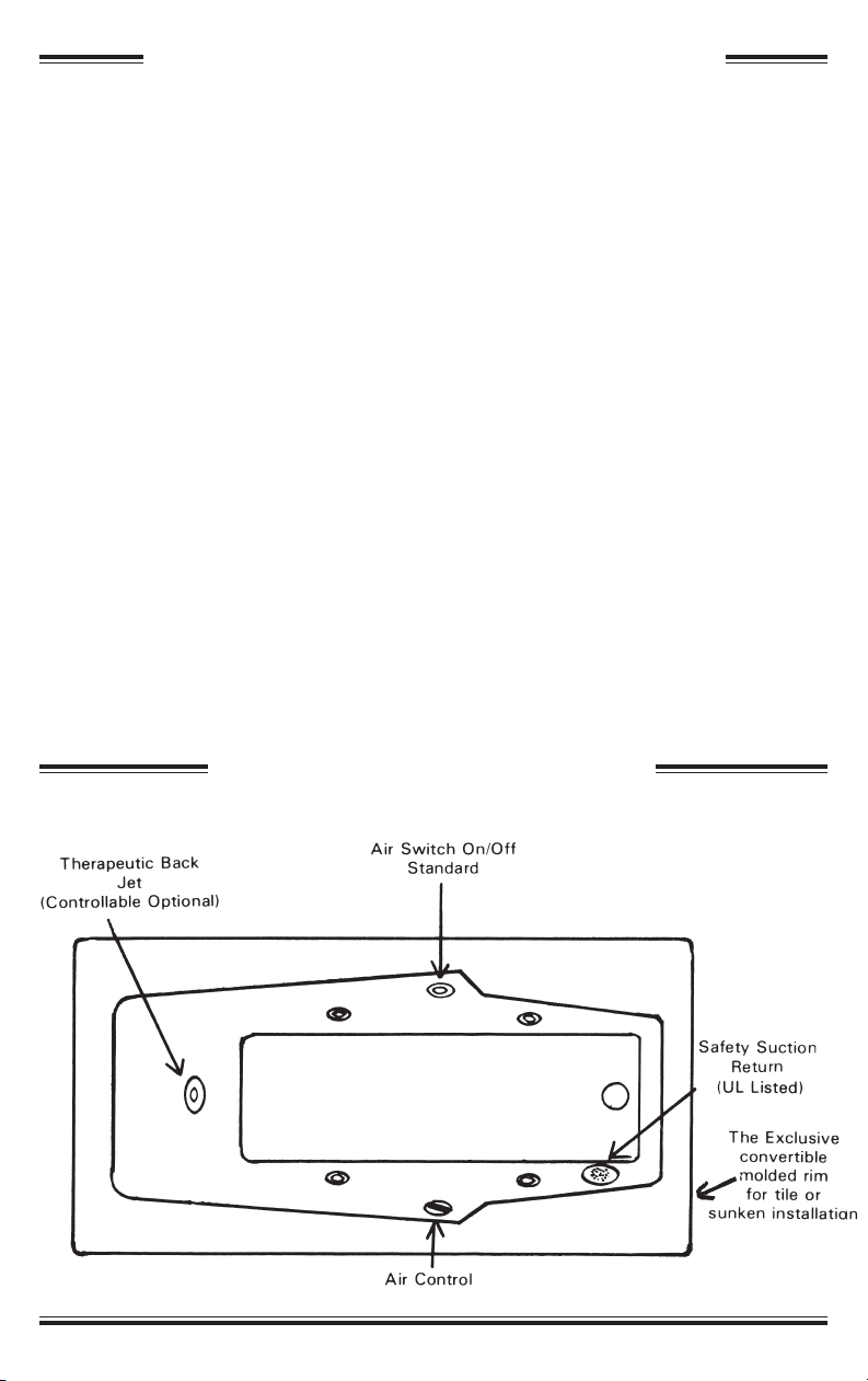
2. To turn unit ON or OFF simply push on or off air switch located per diagram
shown below. A gentle push on or off is all that is necessary.
3. All jets are adjustable by simply turning the jet covers with the palm of the hand
counter clockwise to loosen the jet eye. The eye can be moved with the fingers
for proper direction then tighten the ring cover to secure the eye.
NOTE: Adjustable back-jet, if provided are adjustable on or off as well as
directional. The center section or eye of the jet is simply tightened or loosened
to adjust water flow and it can be moved in any direction desired.
4. After jets are adjusted in the desired position, the air control (see diagram
below) can be adjusted for desired air and water mix from the jets. This is for
personal comfort only and can be adjusted as desired.
PICTORIAL EXAMPLE
7
Page 9

CARE AND CLEANING
Units are easy to keep clean and sparkling. Simply use warm water and a leading
liquid cleaner. Never use abrasives as this will dull the surface of the unit or leave
scratches. In cases where abrasives were used however, the finish can be
restored by applying fine rubbing compound with a soft cloth, rubbing vigorously
and then wiping off residue. Wax the area with prescribed procedures from a
leading automotive wax manufacturer. Stubborn stains can be removed with
solvents such as turpentine, paint thinner or acetone. In cases where this is
necessary use the compounding and wax procedures shown above to finish the
area where the solvents were used.
CAUTION: Do not use cleaning agents that have a vegetable base; they can
promote bacterial growth. Do not use abrasive cleansers and do not allow
solvent-based cleaners or cleaners containing petroleum distillates to
remain in contact with bath surfaces for long periods of time as they can
damage the unit’s finish. Do not allow highly alkaline cleaners to remain in
contact with the bath surfaces or damage to the finish may result. Read and
follow the cleaner manufacturer’s directions.
IMPORTANT! FLUSH YOUR HYDROMASSAGE SYSTEM TWICE A MONTH
OR MORE DEPENDING ON USAGE. USE THE FOLLOWING SEQUENCE:
• Set air controls to fully closed position.
• Fill bath with hot water 2” to 3” above the highest jets.
• Add 2 teaspoons of a low foaming dishwasher detergent such as Calgonite or
Cascade, and 4 ounces of household bleach such as Clorox, to the water.
• Run hydromassage for 10-15 minutes and then drain bath.
• Fill with cold water 2” to 3” above the highest jets and run unit for another
5-10 minutes. Drain bath, and wipe dry with a soft cloth.
NOTE: Hydromassage action can cause even a small amount of bubble bath,
bath soap, shampoo, or body oil to foam excessively. For this reason, refrain from
using these products during the hydromassage cycle.
8
Page 10

LIMITED WARRANTY
The Manufacturer warrants to the original retail purchaser (herein “Original
purchaser”) that the unit (herein “the unit”) to which this warranty is affixed is free from
hidden defects in materials and workmanship under normal use and service for (3)
years from the date of invoice or as otherwise agreed to in writing by the Manufacturer.
The Manufacturer shall not be liable under this warranty if, in this judgement, any
person or persons installing the unit have reason to know of any defect therein prior
to installation. The Manufacturer’s liability and the original purchaser’s exclusive
remedies under this warranty shall be limited to the repair at its factory, or at the
Manufacturer’s option, either the refund of the full purchase price or replacement,
without charge except transportation and installation, of any part or parts of the unit
which in the Manufacturer’s judgement are defective in material or workmanship. Any
repaired or replaced part of the unit shall be warranted to the original purchaser only
for the unexpired portion of the original warranty. This warranty shall not apply to any
unit which has been repaired other than as indicated herein or which has been altered
in any way which, in the judgement of the Manufacturer, affects it’s condition or
performance, and is void if defect is caused by wind, storm, fire, accident, or similar
casualty, or by improper use, installation, maintenance or storage.
Except as required by law, the Manufacturer shall not be liable to the purchaser or
anyone else for damages, including but not limited to consequential damages and
damages by reason of injury to any person, due to any defect in or malfunction of the
unit or any part or parts thereof, or for any other reason.
Some states do not allow exclusion or limitation of incidental or consequential
damages, so the above limitation or exclusion may not apply to you.
“To the extent allowable under specific state laws the obligations of the
Manufacturer hereunder are expressly granted in lieu of all warranties, whether
expressed or implied, including but not limited to implied warranties or
merchantability and fitness for a particular purpose, except that implied
warranties shall be effective for (3) three years from the date of invoice of this
unit after said (3) three years all implied warranties are disclaimed and excluded
from this warranty.”
The warranty does not cover pumps, timers, doors, steam units or any accessory not
manufactured by the Manufacturer. These items are warranted by their respective
manufacturers. For information concerning these items contact your supplier of the
Manufacturer units or write:
ATTN: Consumer Affairs
1610 J. P. Rodgers Drive • Valdosta, Georgia 31601 • (800) 333-0805.
510 E. Jones Street • Wilson, NC 27893 • 1(800) 775-8827
Some states do not allow limitations on how long an implied warranty lasts, so the
above limitation may not apply to you.
9
Page 11

TROUBLESHOOTING GUIDE
WARNING–This guide is meant for a general aid only. All electrical problems
should be corrected by a qualified electrician or authorized service
representative. For warranty service contact your dealer, wholesale
distributor or write:
ATTN: Consumer Affairs
1610 J. P. Rodgers Drive 510 E. Jones Street
Valdosta, Georgia 31601 Wilson, NC 27893
1(800) 333-0805 1(800) 775-8827
SYMPTOMS PROBABLE CAUSES RECOMMENDED ACTION
Directional ball does not
move freely/too tight.
Motor does not turn
on or off.
Motor turns, water is
pumping, but there is no
air injection.
Motor shuts off
automatically.
Motor turns on but no
water is pumping.
A. Retainer is tight/loose.
A. No power to motor.
B. Tubing kinked or broken.
C. Tubing disconnected from actuator
on power panel.
A. Air aspirator is closed.
B. Orifice(s) are missing.
A. Motor overheated and protection
activated.
B. GFCI (ELCB) trips
A. Low water level in bath (below
suction inlet).
B. Suction air leak.
C. Suction blocked.
D. Jets blocked.
A. Tighten/Loosen Retainer
A. Set/Reset GFCI (ELCB) breaker
B. Check tubing and replace
C. Reconnect tubing.
A. Open air aspirator
B. Tighten or replace orifices in jet housing.
A. Check for blockage at motor vents.
Remove blockage and allow motor to cool.
Check for suction blockage. Remove
blockage and allow motor to cool. Check
for jet blockage. Remove blockage and
allow motor to cool.
B. Refer to installer/dealer.
A. Fill bath to proper level.
B. Tighten all clamps and fittings on
the suction side of the pump
C. Remove hood and hair-screen. Clear
blockage.
D. Remove blockage.
10
Page 12

The manufacturer represents that the product to which
this label is affixed (a) duplicates samples independently
tested by NAHB Research Center, and certified to
conform to the requirements of HUD UM Bulletin No. 73a
and the appropriate ANSI Z124 standard and (b) has
been manufactured under quality controls deemed
appropriate by the manufacturer and periodically
revie wed by the Research Cent er. Flame spread rating
less than 200 by ASTM E84.
6028
– INSTALLATION PRECAUTIONS –
A) NEVER ATTEMPT TO RUN THE PUMP/MOTOR WHILE THE
WHIRLPOOL BATHTUB APPLIANCE IS DRY.
B) DO NOT LIFT THE WHIRLPOOL BATHTUB APPLIANCE BY THE
PLUMBING AT ANY TIME.
C) PIPING SUBJECT TO UNDUE CORROSION/EROSION OR
MECHANICAL DAMAGE SHALL BE PROTECTED IN AN
APPROVED MANNER.
D) ALL INSTALLATIONS MUST HAVE A CLASS A GROUND-FAULT
CIRCUIT-INTERRUPTER (GFCI) WHICH WILL PROVIDE
ADDITIONAL PROTECTION AGAINST LINE-TO-GROUND SHOCK
HAZARD. A 120 V, 15 A, 60 Hz SEPARATE CIRCUIT IS REQUIRED.
Manufacturing Facilities Located at:
1610 J.P. Rodgers Drive
Valdosta, Georgia
800-333-0808
510 E. Jones Street
Wilson, North Carolina
800-775-8827
Colson Printing Company 92646
 Loading...