

Part Number: P1512123 R0
Revised: 11/3/10
Read this manual before using product. Failure
to follow instructions and safety precautions can
result in serious injury, death, or property
damage. Keep manual for future reference.
CONVEYOR S-DRIVE 55’-100’
1500 P / 2000 P SERIES
OPERATION MANUAL

This product has been designed and constructed according to general engineering
standardsa. Other local regulations may apply and must be followed by the operator.
We strongly recommend that all personnel associated with this equipment be trained
in the correct operational and safety procedures required for this product. Periodic
reviews of this manual with all employees should be standard practice. For your
convenience, we include this sign-off sheet so you can record your periodic reviews.
Date Employee Signature Employer Signature
a. Standards include organizations such as the American Society of Agricultural and Biological Engineers,
American National Standards Institute, Canadian Standards Association, International Organization for
Standardization, and/or others.
=

BATCO - CONVEYOR S-DRIVE 55’-100’
1500 P / 2000 P SERIES
TABLE OF CONTENTS
1. Introduction.......................................................................................................................... 5
2. Safety First............................................................................................................................ 7
2.1. General Safety ......................................................................................................... 8
2.2. Transport and Placement Safety.............................................................................. 9
2.3. Operational and Maintenance Safety..................................................................... 10
2.4. Hydraulic Safety..................................................................................................... 12
2.5. Storage Safety........................................................................................................ 12
2.6. Tire Safety.............................................................................................................. 12
2.7. Battery Safety......................................................................................................... 12
2.8. Gas Engine Safety ................................................................................................. 13
2.9. PTO Driveline Safety.............................................................................................. 13
2.10. Electric Motor Safety............................................................................................ 13
2.11. Safety Decal Locations......................................................................................... 13
2.11.1. Decal Installation.................................................................................... 14
2.11.2. Decal Locations...................................................................................... 14
3. Components and Controls................................................................................................ 17
4. T ranspor t............................................................................................................................. 19
4.1. Pre-Transport Checklist.......................................................................................... 19
4.2. Transport Procedure .............................................................................................. 19
5. Placement ........................................................................................................................... 21
5.1. Under Hopper Bottom Bins .................................................................................... 21
5.2. Filling Bins.............................................................................................................. 21
6. Operation ............................................................................................................................ 23
6.1. Pre-Operation Checklist......................................................................................... 23
6.2. Machine Break-In and Operation ........................................................................... 23
6.2.1. Drive Setup............................................................................................... 24
6.2.2. Starting Conveyor..................................................................................... 24
6.2.3. Conveyor Shutdown................................................................................. 25
6.2.4. Emergency Shutdown .............................................................................. 26
6.2.5. Re-starting (Full Tube).............................................................................. 26
6.2.6. Conveyor Operating Angles ..................................................................... 26
6.2.7. Belt Speed................................................................................................ 26
6.2.8. Operating Tips.......................................................................................... 27
7. Storage................................................................................................................................ 29
P1512123 3

BATCO - CONVEYOR S-DRIVE 55’-100’
1500 P / 2000 P SERIES
TABLE OF CONTENTS
8. Maintenance........................................................................................................................ 31
8.1. Maintenance Schedule........................................................................................... 31
8.1.1. Initial start-up servicing............................................................................. 31
8.1.2. 8 Hours or Daily........................................................................................ 31
8.1.3. 40 Hours or Weekly.................................................................................. 32
8.1.4. 200 Hours or Annually.............................................................................. 32
8.2. Maintenance Checklist ........................................................................................... 33
8.3. Service & Maintenance Procedures....................................................................... 34
8.3.1. Fluids and Lubricants................................................................................ 34
8.3.2. Greasing................................................................................................... 34
8.3.3. Conveyor Belt Tension ............................................................................. 34
8.3.4. Belt Tension Instructions .......................................................................... 35
8.3.5. Conveyor Belt Alignment.......................................................................... 36
8.3.6. Belt Relacing............................................................................................. 39
8.3.7. Conveyor Belt Replacement..................................................................... 39
8.3.8. Drive Belt Tension & Alignment (Gas and Electric Drive)......................... 41
8.3.9. Driveline Shield (PTO Drive)..................................................................... 41
8.3.10. Tube Alignment Cable Truss.................................................................. 41
9. Troubleshooting ................................................................................................................. 43
10. Appendix........................................................................................................................... 47
10.1. S-drive 55’-120’ Specifications............................................................................. 47
10.2. Conveyor Product Chart....................................................................................... 48
New Equipment Warranty ....................................................................................................... 49
4 P1512123

BATCO - CONVEYOR S-DRIVE 55’-100’ 1. INTRODUCTION
1500 P / 2000 P SERIES
1.Introduction
Congratulations on your choice of a Batco Conveyor to complement your agricultural operation. This equipment has been designed and manufactured to meet
the needs of the discriminating buyer for the efficient movement of grain, pulse
crops, fertilizer, and most other granular materials.
Safe, efficient, and trouble-free operation of your conveyor requires that you, and
anyone else who will be operating or maintaining the conveyor, read and understand the safety, operation, maintenance, and troubleshooting information in this
manual.
¨
Equipment is available in various combinations. In most cases, the following
instructions will apply to all machines. Where the assembly information varies,
additional instructions will be included and will be indicated with an arrow.
Keep this manual handy for frequent reference and to pass on to new operators
or owners. Call your Batco distributor or dealer if you need assistance, information, or additional copies of the manual.
Always give your dealer the serial number of your Batco Grain Conveyor when
ordering parts or requesting service or other information.
The serial number plate is located where indicated above by the arrow on the
frame. Please mark the number in the space provided for easy reference.
Model#
Serial #
Production Year
P1512123 5

1. INTRODUCTION BATCO - CONVEYOR S-DRIVE 55’-100’
1500 P / 2000 P SERIES
6 P1512123
BATCO - CONVEYOR S-DRIVE 55’-100’ 2. SAFETY FIRST
1500 P / 2000 P SERIES
2.Safety First
The Safety Alert symbol to the left identifies important safety messages on the
product and in the manual. When you see this symbol, be alert to the possibility of personal injury or death. Follow the instructions in the safety messages.
Why is SAFETY important to you?
Three big reasons:
• Accidents disable and kill.
• Accidents cost.
• Accidents can be avoided.
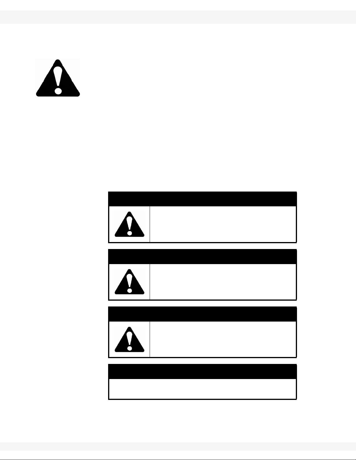
SIGNAL WORDS
Note the use of the signal words DANGER, WARNING, CAUTION, and NOTICE
with the safety messages. The appropriate signal word for each message has
been selected using the definitions below as a guideline.
The Safety Alert symbol means ATTENTION, BE ALERT!, YOUR SAFETY IS
INVOLVED.
DANGER
Indicates an imminently hazardous situation
that, if not avoided, will result in serious injury
or death.
WARNING
Indicates a hazardous situation that, if not
avoided, could result in serious injury or
death.
CAUTION
Indicates a hazardous situation that, if not
avoided, may result in minor or moderate
injury.
NOTICE
Indicates a potentially hazardous situation that, if not
avoided, may result in property damage.
P1512123 7

2. SAFETY FIRST BATCO - CONVEYOR S-DRIVE 55’-100’
2.1. GENERAL SAFETY 1500 P / 2000 P SERIES
2.1. GENERAL SAFETY
Important: The general safety section includes instructions that apply to all safety practices.
Any instructions specific to a certain safety practice (e.g., assembly safety), can
be found in the appropriate section. Always read the complete instructional
sections and not just these safety summaries before doing anything with the
equipment.
YOU are responsible for the SAFE use and maintenance of your equipment.
YOU must ensure that you and anyone else who is going to work around the
equipment understands all procedures and related SAFETY information
contained in this manual.
Remember, YOU are the key to safety. Good safety practices not only protect
you, but also the people around you. Make these practices a working part of your
safety program.
• It is the equipment owner and the operator's responsibility to read and understand ALL safety instructions, safety decals, and manuals and follow them
before assembling, operating, or maintaining the equipment. All accidents
can be avoided.
• Equipment owners must give instructions and review the information initially
and anually with all personnel before allowing them to operate this product.
Untrained users/operators expose themselves and bystanders to possible
serious injury or death.
• Use this equipment for its intended purposes only.
• Do not modify the equipment in any way. Unauthorized modification may
impair the function and/or safety, and could affect the life of the equipment.
Any modification to the equipment voids the warranty.
• Do not allow children, spectators, or bystanders within the work area.
• Have a first-aid kit available for use should the need arise, and know how to
use it.
• Provide a fire extinguisher for use in case of an accident. Store in a highly visible place.
• Wear appropriate protective gear . This list includes, but
is not limited to:
• a hard hat
•gloves
• protective shoes with slip-resistant soles
• protective goggles
• hearing protection
• For Powered Equipment: before servicing, adjusting, or repairing powered
equipment, unplug, place all controls in neutral or off position, stop the engine
or motor , remove ignition key or lock out power source, and wait for all moving parts to stop.
8 P1512123
BATCO - CONVEYOR S-DRIVE 55’-100’ 2. SAFETY FIRST
1500 P / 2000 P SERIES 2.2. TRANSPORT AND PLACEMENT SAFETY
• Follow good shop practices:
• keep service area clean and dry
• be sure electrical outlets and tools are properly
grounded
• use adequate light for the job at hand
• Think SAFETY! Work SAFELY!
2.2. TRANSPORT AND PLACEMENT SAFETY
• Be sure that conveyor is empty before raising or lowering.
• Check with local authorities regarding transport on public roads. Obey all
applicable laws and regulations.
• Always travel at a safe speed, never exceeding
20 mph (32 km/h). Reduce speed on rough
surfaces. Use caution when turning corners or
meeting traffic.
• Make sure the SMV (slow moving vehicle)
emblem and all the lights and reflectors that
are required by local authorities are in place,
are clean, and can be seen by all over-taking
and oncoming traffic. Always use hazard-warning flashers on tractor/towing vehicle when
transporting unless prohibited by law.
• Do not allow riders on the machine, towing
vehicle, tractor, or skid steer during transport.
• Stay away from overhead obstructions and
power lines when operating and transporting.
Electrocution can occur without direct contact.
• Fully lower conveyor before transporting, and
only raise when next to storage facility.
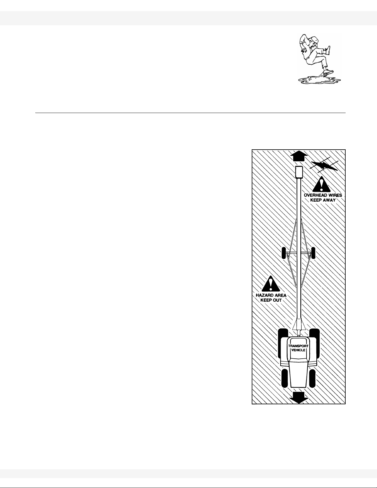
• Review the work safety area diagram before
starting work.
• Attach a conveyor to towing vehicle with a pin
and retainer. Always attach safety chain(s).
• Chock front and rear conveyor and tractor
wheels before operating.
• Do not raise the intake end above drawbar,
conveyor upending may occur.
• Be familiar with the machine transport hazard
area. If anyone enters the hazard area, shut
down the machines immediately. Clear the
area before restarting.
• Do not transport conveyor on slopes greater than 20°.
• Wheels must be free to move when raising or lowering conveyor. Do not use
conveyor as a crane or hoist.
P1512123 9

2. SAFETY FIRST BATCO - CONVEYOR S-DRIVE 55’-100’
2.3. OPERATIONAL AND MAINTENANCE SAFETY 1500 P / 2000 P SERIES
• Long conveyors have a large turning radius. Allow ample room for turning as
discharge end may swing dramatically.
• Only move the conveyor with a tractor/towing vehicle. Never move by hand.
2.3. OPERATIONAL AND MAINTENANCE SAFETY
• Keep hands, feet, hair, clothing, and jewelery away from all moving and/or
rotating parts.
• Stay away from overhead obstructions and power lines; electrocution may
occur without direct contact.
• Do not operate with any of the guards removed.
• The machine is closely balanced. Do not lift unless there is a downward
weight on the intake end to prevent upending.
¨
• Set park brake on tractor before starting.
• Lower conveyor to its lowest position when not in use.
• Operate conveyor on level ground free of debris. If ground is uneven, anchor
the conveyor to prevent tipping or upending.
• Place stands or blocks under the frame before working beneath the machine.
• Always work with a second person around conveyor in case of accident.
• Empty conveyor before raising or lowering.
• Do not get on or beneath conveyor when raising or lowering.
• Do not lift intake above tow bar height or conveyor may upend.
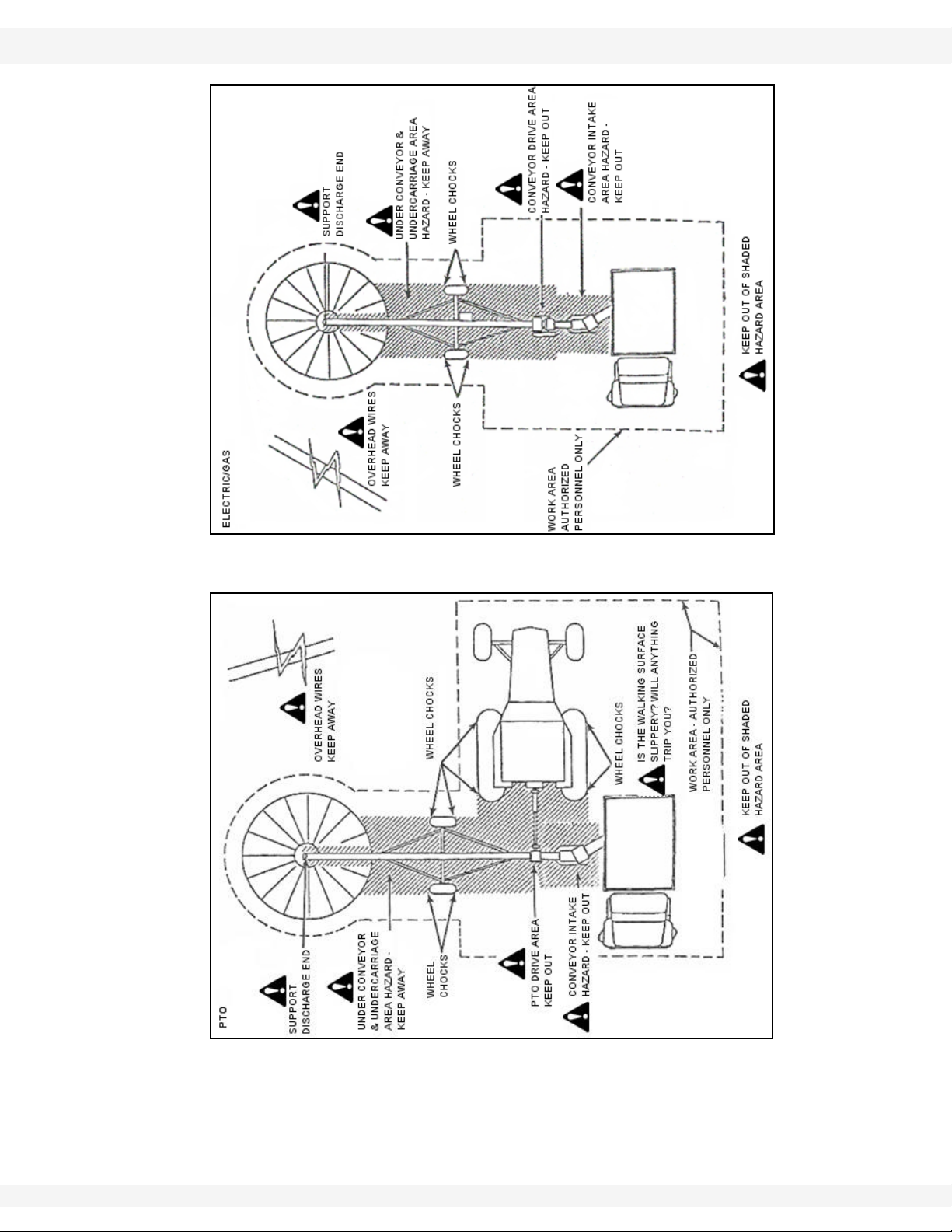
• Be familiar with the machine hazard area shown in Figure 2.1 and 2.2. If anyone enters the hazard area, shut down the machines immediately. Clear the
area before restarting.
10 P1512123
BATCO - CONVEYOR S-DRIVE 55’-100’ 2. SAFETY FIRST
1500 P / 2000 P SERIES 2.3. OPERATIONAL AND MAINTENANCE SAFETY
Figure 2.1 Workplace Hazard Area (Electric/Gas Area)
Figure 2.2 Workplace Hazard Area (PTO Drive)
P1512123 11

2. SAFETY FIRST BATCO - CONVEYOR S-DRIVE 55’-100’
2.4. HYDRAULIC SAFETY 1500 P / 2000 P SERIES
2.4. HYDRAULIC SAFETY
• Always place all tractor hydraulic controls in neutral before disconnecting
from tractor or working on hydraulic system.
• Make sure that all components in the hydraulic system are kept in good condition and are clean.
• Replace any worn, cut, abraded, flattened, or crimped hoses.
• Do not attempt any makeshift repairs to the hydraulic fittings or hoses by
using tape, clamps, or cements. The hydraulic system operates under
extremely high-pressure. Such repairs will fail suddenly and create a hazardous and unsafe condition.
• Wear proper hand and eye protection when searching for a high-pressure
hydraulic leak. Use a piece of wood or cardboard as a backstop instead of
hands to isolate and identify a leak.
• If injured by a concentrated
high-pressure stream of
hydraulic fluid, seek medical
attention immediately. Serious infection or toxic reaction
can develop from hydraulic
fluid piercing the skin surface.
2.5. STORAGE SAFETY
• Store the unit in an area away from human activity.
• Do not permit children to play on or around the stored equipment.
• Fully lower conveyor before storing.
2.6. TIRE SAFETY
• Failure to follow proper procedures when mounting a tire on a wheel or rim
can produce an explosion that may result in serious injury or death.
• Do not attempt to mount a tire unless you have the proper equipment and
experience to do the job.
• Have a qualified tire dealer or repair service perform required tire maintenance.
• When replacing worn tires, make sure they meet the original tire specifications. Never undersize the replacement tire.
• Do not weld to the tire rim with the tire mounted on the rim. This action may
cause an explosion which could result in serious injury or death.
• Inflate tires to the manufacturers's recommended pressure.
2.7. BATTERY SAFETY
• Wear safety glasses when working near batteries.
12 P1512123

BATCO - CONVEYOR S-DRIVE 55’-100’ 2. SAFETY FIRST
1500 P / 2000 P SERIES 2.8. GAS ENGINE SAFETY
• Make certain the battery or terminal covers are in place and in good working
order.
• Keep all sparks and flames away from batteries; gas given off by electrolyte is
explosive.
• Avoid contact with battery electrolyte. W ash off any spilled electrolyte immediately.
• Do not tip batteries more than 45° to avoid electrolyte loss.
• To avoid injury from sparks or short circuits, disconnect battery ground cable
before servicing any part of an electrical system.
2.8. GAS ENGINE SAFETY
• Read and understand the operating and maintenance instructions that came
with the gas engine.
2.9. PTO DRIVELINE SAFETY
• To prevent serious injury or death:
• Keep body, hair, and clothing away from rotating PTO driveline.
• Do not operate equipment unless all driveline, tractor, and equipment shields
are in place and in good working order.
• Make certain the driveline shields turn freely on driveline.
• Make certain the driveline is securely attached at both ends.
• Do not exceed operating speed of 540 rpm.
• Keep u-joint angles small and equal. Do not exceed maximum recommended
length for PTO driveline.
• Do not exceed manufacturer’s recommended operating length.
• Set the tractor brake and block wheels on the tractor and the implement to
insure proper spacing of the PTO shaft at all times.
• Make sure driveline is properly secured to prevent damage during transport.
2.10. ELECTRIC MOTOR SAFETY
• To prevent serious injury or death, only qualified personnel should service
electrical components.
• Keep electrical components in good repair.
• Ground electric motor before using.
• Inspect drive belts before using. Replace if frayed or damaged.
2.11. SAFETY DECAL LOCATIONS
• Keep safety decals clean and legible at all times.
• Replace safety decals that are missing or have become illegible. See decal
location figures below.
• Replaced parts must display the same decal(s) as the original part.
P1512123 13

2. SAFETY FIRST BATCO - CONVEYOR S-DRIVE 55’-100’
2.11. SAFETY DECAL LOCATIONS 1500 P / 2000 P SERIES
• Safety decals are available from your distributor, dealer, or factory.
2.11.1. DECAL INSTALLATION
1. Decal area must be clean and dry, with a temperature above 10°C (50°F).
2. Decide on the exact position before you remove the backing paper.
3. Align the decal over the specified area and carefully press the small portion
with the exposed sticky backing in place.
4. Slowly peel back the remaining paper and carefully smooth the remaining
portion of the decal in place.
5. Small air pockets can be pierced with a pin and smoothed out using the sign
backing paper.
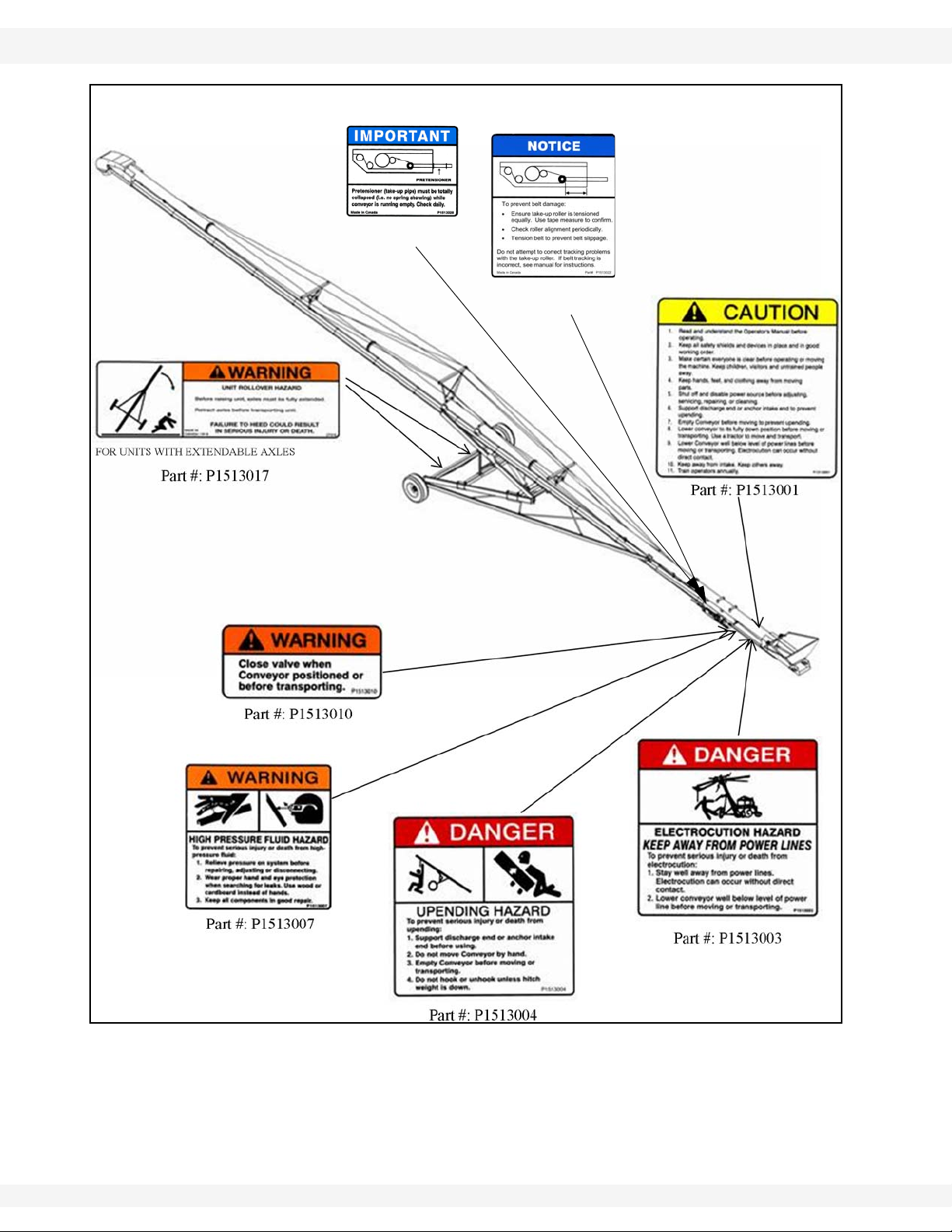
2.11.2. DECAL LOCATIONS
Replicas of the safety decals that are attached to the equipment are shown
below. Good safety requires that you familiarize yourself with the various safety
decals and the areas or particular functions that the decals apply to as well as
the safety precautions that must be taken to avoid serious, injury, death, or
damage.
14 P1512123
BATCO - CONVEYOR S-DRIVE 55’-100’ 2. SAFETY FIRST
PART #: P1513022
PART # P1513028
1500 P / 2000 P SERIES 2.11. SAFETY DECAL LOCATIONS
Figure 2.3 Safety Decal Locations (65’- 105’ Conveyors)
P1512123 15

2. SAFETY FIRST BATCO - CONVEYOR S-DRIVE 55’-100’
PART #: P1513008
BENEATH PLASTIC GUARD
PART #: P1513002
ELECTRIC MODELS
PART #: P1513009
PART #: P1513005
2.11. SAFETY DECAL LOCATIONS 1500 P / 2000 P SERIES
Figure 2.4 Gas/Electric Drive Safety Decals
Figure 2.5 PTO S-Drive Safety Decal
16 P1512123

BATCO - CONVEYOR S-DRIVE 55’-100’ 3. COMPONENTS AND CONTROLS
HOOD
SPOUT
MAIN TUBE
RETURN ROLLER
OR WG ROLLER
TRUSS
AXLE/EXTENDABLE
HOPPER
S-DRIVE
SCISSOR FRAME
1500 P / 2000 P SERIES
3.Components and Controls
Before operating the conveyor, all operators should familiarize themselves with
the location and function of the components and controls. See Table 3.1 and
Figure 3.1 for details.
Figure 3.1 Typical Conveyor Components
P1512123 17

3. COMPONENTS AND CONTROLS BATCO - CONVEYOR S-DRIVE 55’-100’
1500 P / 2000 P SERIES
18 P1512123

BATCO - CONVEYOR S-DRIVE 55’-100’ 4. TRANSPORT
Warning: Before continuing, please reread the safety information relevant to this section at
the beginning of this manual. Failure to follow the safety instructions can result in serious
injury, death, or property damage.
1500 P / 2000 P SERIES 4.1. PRE-TRANSPORT CHECKLIST
4.Transport
CAUTION
It may be necessary to raise the outlet end
above the storage facility to provide clearance
to raise the intake end.
4.1. PRE-TRANSPORT CHECKLIST
Before transporting conveyor , ensure that:
1. Conveyor is in the fully lowered position.
2. Extendable axles are placed in transport position (if equipped). Use jack to
aid adjustment.
3. Attach conveyor to towing vehicle with a pin and retainer. Always attach
safety chain(s).
¨
¨
¨
4. On electric motor models, unplug the power cord, wrap around frame, and
secure to prevent dragging.
5. On PTO drive models, place the driveline in its stowed position before
moving or transporting.
6. For gas drive models, shut off fuel supply.
4.2. TRANSPORT PROCEDURE
1. Check with local authorities regarding conveyor transport on public roads.
Obey all applicable laws and regulations.
2. Make sure the SMV (slow moving vehicle) emblem and all the lights and
reflectors that are required by the local highway and transport authorities are
in place, are clean, and can be seen clearly by all overtaking and oncoming
traffic.
3. Always use hazard warning flashers on tractor or towing vehicle when
transporting unless prohibited by law.
4. Always travel at a safe speed. Use caution when turning corners or meeting
traffic.
5. It is not recommended that the machine be transported faster than 20 mph
(32 km/h). Table 4.1 references the acceptable transport speed as per the
ratio of tractor weight versus conveyor weight. See “Appendix” on page 47
P1512123 19
for conveyor weights

4. TRANSPORT BATCO - CONVEYOR S-DRIVE 55’-100’
4.2. TRANSPORT PROCEDURE 1500 P / 2000 P SERIES
Table 4.1 Speed versus Weight Ratio
Weight or fully equipped or loaded
Road Speed
Up to 32 km/h (20 mph) 1 to 1, or less
Up to 16 km/h (10 mph) 2 to 1, or less
Do not tow if More than 2 - 1
implement(s) relative to weight of
towing machine
6. Use caution when moving conveyors over rolling terrain. In severe dips the
discharge end may contact the ground
7. Never go across slopes of more than 11°. It is better to go straight up or
straight down the slope.
DANGER
Stay away from overhead obstructions and
power lines when operating and transporting.
Electrocution can occur without direct contact.
8. Long conveyors have a large turning radius. Allow ample room for turning as
discharge end may swing dramatically.
20 P1512123

BATCO - CONVEYOR S-DRIVE 55’-100’ 5. PLACEMENT
Warning: Before continuing, please reread the safety information relevant to this section at
the beginning of this manual. Failure to follow the safety instructions can result in serious
injury, death, or property damage.
1500 P / 2000 P SERIES 5.1. UNDER HOPPER BOTTOM BINS
5.Placement
5.1. UNDER HOPPER BOTTOM BINS
BEFORE MOVING CONVEYOR UNDERNEATH HOPPER BIN:
1. Confirm that hopper is centered between the hopper bin vertical legs. This
ensures that the operator has adequate clearance.
¨
Important: 5. Raise the conveyor spout to desired height, and close ball valve.
2. Ensure the conveyor motor will not make contact with the hopper cone when
in its final position.
3. Collapse the cloth hopper until it is positioned under the bin.
4. Move conveyor into place.
6. Make sure that gravel is not jammed against the belt under the hopper.
Ensure that the ball valve is closed. Failure to do so will
cause the frame to lower, damaging the conveyor.
5.2. FILLING BINS
1. Back the machine up to the storage facility while it is in its lowered configuration. If equipped with extendable axles, place in extended position. Use
jack to aid adjustment.
2. Set the park brake on the tractor before dismounting.
3. Use the hydraulic scissor-lift to raise the machine so it clears the storage
facility.
4. Slowly back the machine up until the outlet is over the opening in the storage
facility.
5. Use the hydraulics to slowly lower the machine to the bin.
Do not rest the spout or hood on the bin. This may cause
hood or belt damage.
NOTICE
NOTICE
6. Place chocks in the front and back of each wheel.
7. When releasing conveyor from the towing vehicle, test the intake end for
downward weight.
P1512123 21

5. PLACEMENT BATCO - CONVEYOR S-DRIVE 55’-100’
5.2. FILLING BINS 1500 P / 2000 P SERIES
8. Unhook the unit from the tractor or towing vehicle and lower hopper to the
ground.
WARNING
Upending hazard:
Do not hook or unhook hitch unless weight is
down.
9. Lower the machine to the bin, but do not let it rest on the bin.
10. Close ball valve and disconnect hydraulic hose.
11. Remove the hitch from the machine to prevent interfering with other
equipment.
12. Prior to operating the conveyor, review Section 2.3. and follow all set-up
instructions.
13. Check angle of machine. Ensure that the machine angle is less than the
angle of repose of the material to be moved. See Section Section 10.2. on
pg. 48 for more help.
WARNING
Unit Rollover Hazard:
Before raising the unit, axles must be fully
extended.
Retract axles before transporting unit.
Failure to follow these procedures could result
in serious injury or death.
22 P1512123

BATCO - CONVEYOR S-DRIVE 55’-100’ 6. OPERATION
Warning: Before continuing, please reread the safety information relevant to this section at
the beginning of this manual. Failure to follow the safety instructions can result in serious
injury, death, or property damage.
1500 P / 2000 P SERIES 6.1. PRE-OPERATION CHECKLIST
6.Operation
6.1. PRE-OPERATION CHECKLIST
BEFORE OPERATING THE CONVEYOR EACH TIME:
• Service the machine per the schedule outlined in Section 8.1.
• Use only a tractor, gas engine, or electric motor of adequate power to operate
the machine. See Section10.2. on page 48.
• Check that drive (Gas/Electric Motors) and conveying belts are not frayed or
damaged and that they are properly adjusted and aligned. See Maintenance
section.
• Ensure wheels are chocked.
• Check that hopper and spout areas are free of obstructions.
• Support discharge end or anchor intake end before using.
6.2. MACHINE BREAK-IN AND OPERATION
Although there are no operational restrictions on the conveyor when used for the
first time, it is recommended that the following items be checked:
BEFORE STARTING:
1. Read the conveyor and motor (if equipped) operation manuals.
2. During the first few minutes of operation, check the conveyor belt alignment
to ensure preset alignment does not vary under loaded conditions. See
Maintenance section.
AFTER OPERATING OR TRANSPORTING FOR 1/2 HOUR:
1. Re-torque all the wheel bolts.
2. Re-torque fasteners and hardware.
3. Check the drive and conveyor belt tension and alignment. Tension or align as
required. See Maintenance section.
AFTER OPERATING FOR 5 AND 10 HOURS:
1. Re-torque all wheel bolts, fasteners, and hardware.
2. Check the drive and conveyor belt tension and alignment. Tension or align as
required.
P1512123 23

6. OPERATION BATCO - CONVEYOR S-DRIVE 55’-100’
6.2. MACHINE BREAK-IN AND OPERATION 1500 P / 2000 P SERIES
6.2.1. DRIVE SETUP
PTO DRIVE MODEL:
1. Back the tractor into position.
2. Chock tractor wheels.
3. Attach PTO shaft.
ELECTRIC MOTOR MODEL:
1. Have a certified electrician provide power to the machine.
2. Provide convenient shutdown switches and comply with local electrical
codes.
3. Use a totally enclosed electric motor when conveying in extremely dusty
conditions. Be sure electric motor is properly grounded.
GAS ENGINE MODEL:
1. Have engine installed by an electrical technician.
2. Ensure electrical cables are properly grounded.
3. Ensure drive belts are properly aligned and in good condition.
4. Ensure that fuel lines are in good condition and are not contacting any
obstructions.
5. Fill system with fuel.
6.2.2. STARTING CONVEYOR
PTO DRIVE:
1. Place all controls in neutral.
2. Engage tractor parking brake.
3. Start tractor and run at low idle.
4. Engage PTO and steadily increas e engine speed to desired speed.
WARNING
Anchoring and/or support of the conveyor
during operation is necessary. When
emptying the conveyor, the weight balance
transfers to the upper end of the machine,
which can cause upending.
24 P1512123

BATCO - CONVEYOR S-DRIVE 55’-100’ 6. OPERATION
1500 P / 2000 P SERIES 6.2. MACHINE BREAK-IN AND OPERATION
Important: Position tractor to keep u-joint angles equal and as small as possibl.
CAUTION
Hydraulic safety ball valve must be fully
opened before lifting or lowering the
conveyor.
Valve must be closed when conveyor is in a
fixed position to prevent the hydraulic cylinder
from creeping downward during operation.
ELECTRIC DRIVE:
1. Turn the electric motor ON.
2. Engage belt drive if equipped.
GAS ENGINE DRIVE:
1. Disengage gas engine drive belt or electric clutch.
2. Move throttle to 1/4 position for starting.
3. Use choke, if required.
4. Start engine.
5. Run engine for a couple of minutes until the engine warms.
6. Engage belt drive or electric clutch and increase engine speed to desired
speed.
6.2.3. CONVEYOR SHUTDOWN
PTO MODELS:
1. Run until the belting is empty.
2. Reduce engine speed to low idle.
3. Disengage PTO clutch.
4. Shut off engine and remove ignition key.
CAUTION
Conveyor should not be left in a raised
position for extended periods of time. Fully
lower conveyor to prevent the risk of damage
or personal injury.
ELECTRIC MOTOR MODELS:
1. Run until the belting is empty.
2. Disengaged belt drive if equipped.
3. Turn off motor and lock out power source.
P1512123 25

6. OPERATION BATCO - CONVEYOR S-DRIVE 55’-100’
6.2. MACHINE BREAK-IN AND OPERATION 1500 P / 2000 P SERIES
GAS DRIVE MODELS:
1. Run until the belting is empty.
2. Reduce engine speed to low idle.
3. Disengage belt drive; or disengage electric clutch if unit is equipped with one.
4. Shut off engine.
6.2.4. EMERGENCY SHUTDOWN
Although it is recommended that the tube be emptied before stopping, in an
emergency situation, stop or shut down the power source immediately.
Important: Lock out all power and ensure the machine components come to a stop before
inspecting.
Correct the emergency before resuming work.
6.2.5. RE-STARTING (FULL TUBE)
When the machine is shut down inadvertently or for an emergency, the tube will
still be filled with material.
Important: Since the start-up torque loads are much higher than normal when the tube is
full, restart at low idle engine speed for the PTO and gas engine models.
It may be necessary to tighten the drive belts (Electric/Gas Models) slightly to
handle the heavier than normal loads. (See 8.3.4.)
6.2.6. CONVEYOR OPERATING ANGLES
The coneyor lift can set the tube angle at any position between 12°and 30° when
operating. Because the belt does not have roll back barriers, the material will roll
back if the angle is too steep. Do not position the conveyor at an angle steeper
than the angle of repose of the material to be moved.
See Section 10.2. for help on determining these angles.
Note: The lower the angle, the greater the capacity.
6.2.7. BELT SPEED
The best results are obtained when the input drives are set to provide a belt
speed of 500 to 600 ft/min on the 1500 P series, and 600 to 650 on the 2000 P
series.
Count the number of belt revolutions per minute to determine belt speed.
Approximate belt length is double the length of your machine plus 3’. See
packing slip for belt lengths.
Note: Use the connector splice as a reference when counting belt revolutions.
Contact your dealer or the factory for the appropriate drive components to give
the recommended belt speed.
26 P1512123

BATCO - CONVEYOR S-DRIVE 55’-100’ 6. OPERATION
1500 P / 2000 P SERIES 6.2. MACHINE BREAK-IN AND OPERATION
6.2.8. OPERATING TIPS
• Direct the flow of material into the input hopper in the direction of the belt for
the best capacity.
• Attempting to move material at too steep an angle can result in excessive
slide back and poor capacity.
• Always listen for any unusual sounds or noises. If any are heard, stop the
machine and determine the source. Correct the problem before resuming
work.
• Always close the hydraulic safety ball valve once the machine is positioned.
• Do not run the machine for long periods of time without material on the belting. It increases belt wear.
• Do not support outlet end directly on the storage facility. Tie down the intake
(hopper) or weigh it down to prevent upending.
• To achieve maximum capacity, feed material onto belt until material tube
clearance is 1/2”; do not flood feed hopper.
• On the PTO drive models, align the tractor axis with the coneyor input shaft
to minimize the angles of the universal joints on the PTO driveline.
Note: On the standard hopper conveyor, the best capacity is obtained when the
material is loaded into the hopper as close to the tube as possible.
P1512123 27

6. OPERATION BATCO - CONVEYOR S-DRIVE 55’-100’
6.2. MACHINE BREAK-IN AND OPERATION 1500 P / 2000 P SERIES
28 P1512123

BATCO - CONVEYOR S-DRIVE 55’-100’ 7. STORAGE
WARNING
Before continuing, please reread the safety information relevant to this section at the beginning of this manual. Failure to follow the safety instructions can result in serious injury , death,
or property damage.
1500 P / 2000 P SERIES
7.Storage
TO PROTECT THE CONVEYOR IN STORAGE:
1. Lower the conveyor to its lowest position for storage.
2. Select an area that is dry, level, and free of debris.
3. Remove all residual material from the conveyor.
4. Stop machine so that the belt lacing is inside the tube. This protects the
lacing from weathering.
5. Wash the entire machine thoroughly using a water hose or pressure washer
to remove all dirt, mud, debris, or residue.
6. Inspect all hydraulic hoses (if equipped), fittings, lines, couplers, and valves.
Tighten any loose fittings. Replace any fitting or hose if damaged.
7. Touch up all paint nicks and scratches to prevent rusting.
8. If machine is not equipped with belt weather guards, position it in such a way
as to limit wind exposure to the belt.
9. Place a block under the jack to ensure it will not freeze to the ground in the
winter.
To prepare the conveyor for use after storage, perform general maintenance.
See Section 8.3. for further details.
P1512123 29

7. STORAGE BATCO - CONVEYOR S-DRIVE 55’-100’
1500 P / 2000 P SERIES
30 P1512123

BATCO - CONVEYOR S-DRIVE 55’-100’ 8. MAINTENANCE
Warning: Before continuing, please reread the safety information relevant to this section at
the beginning of this manual. Failure to follow the safety instructions can result in serious
injury, death, or property damage.
1500 P / 2000 P SERIES 8.1. MAINTENANCE SCHEDULE
8.Maintenance
8.1. MAINTENANCE SCHEDULE
8.1.1. INITIAL START-UP SERVICING
Since the belt alignment is preset to run true under a condition of no load, it is
important to check alignment and make adjustments if required during the initial
few minutes of loaded operation. To adjust ali gnment, see Section 8.3.5.
Conveyor Belt Alignment on p a ge 36.
8.1.2. 8 HOURS OR DAILY
ALL MODELS
• Check the conveyor belt tension and alignment. See Section 8.3.3.
PTO DRIVE MODELS
• Grease all grease fittings at 8 - 10 hour intervals.
• Inspect u-joint for wear.
• Ensure that the connection between PTO shaft and spline is secure.
• Inspect guards and ensure they are in good condition and are free to
rotate.
GAS ENGINE DRIVE MODELS
• Check fuel level and add as required.
• Check gearbox oil level.
• Check crankcases oil level and add as required.
• Check drive belt tension and alignment.
• Check that the wet kit oil reservoir level is equipped.
• Refer to gas engine operation manual for further details.
ELECTRIC DRIVE MODELS
• Check drive belt tension and alignment.
• Check gearbox oil level.
P1512123 31

8. MAINTENANCE BATCO - CONVEYOR S-DRIVE 55’-100’
8.1. MAINTENANCE SCHEDULE 1500 P / 2000 P SERIES
8.1.3. 40 HOURS OR WEEKLY
• Check the conveying belt tension and alignment. See Section 8.3.3.
• Check condition of hopper flashing. Be sure it seals the hopper and prevents grain leakage.
• Look for hydraulic leaks and repair if required.
• Clean engine air filter (if equipped).
8.1.4. 200 HOURS OR ANNUALLY
• Check tube for straightness. Adjust cables, if required. See Section 8.3.3.
• Check tire pressure and add air if required. Inflation pressure details can
be found on the tire itself.
• Check roller bearings for wear . Any rollers making noise, getting hot while
running, or that have play should be replaced.
• Repack wheel bearings.
• Wash machine.
• Check gear box oil level (if quipped).
• Inspect roller lagging to see if it is showing signs of wear.
• Check belt lacing. If any clips are worn through, replace all lacing.
• Check hopper flashing for wear and replace any that are worn. Worn
flashing will cause hopper leakage.
NOTICE
Operating the conveyor with a damaged roller will result in
a damaged conveyor belt.
32 P1512123

BATCO - CONVEYOR S-DRIVE 55’-100’ 8. MAINTENANCE
1500 P / 2000 P SERIES 8.1. MAINTENANCE SCHEDULE
8.2. MAINTENANCE CHECKLIST
See Lubrication and Maintenance sections for details of service. Photocopy this
page to continue record keeping.
Use the maintenance checklist provided to keep a record of all scheduled
maintenance.
Note: Not all options will apply to your machine.
Check CL Clean L Lubricate C Change
1
2
3
4
5
6
7
8
8 Hours/Daily Day
Conveyor Belt Tracking
L PTO shaft (3)
Fuel & Oil Level(s)
Day
23
24
25
26
27
28
29
Conveyor Belt Tracking
L PTO shaft (3)
Fuel & Oil Level(s)
Day
45
46
47
48
49
50
51
Conveyor Belt Tracking
L PTO shaft (3)
Fuel & Oil Level(s)
Day
67
68
69
70
71
72
73
Conveyor Belt Tracking-L PTO shaft (3)
Fuel & Oil Level(s)
1
2
3
4
5
6
40 Hours/Weekly Week
7
Belt Tension & Alignment
Conveyor Belt Tracking
Hopper Flashing Condition
Check for Hydraulic Leaks
Electric Drive Models
Drive Belt Tens. & Align.
Gas Engine Drive Models
Drive Belt Tens. & Align.
CL Air Cleaner Foam
200 hours / Annually
Year 1 Year 2 Year 3 Year 1 Year 2 Year 3
Tube Straightness Belt Lacing
Roller Bearings Hopper Flashing
R Wheel Bearings Hydraulic Drive Models
CL Machine L Roller Chain-Input Coupler
Roller Lagging Gas Engine Drive Models
Check Tire Pressure C Engine Oil
9
30
31
52
53
74
75
8
9
11
10
32
54
76
10
12
13
14
15
16
17
18
19
20
21
33
34
35
36
37
38
39
40
41
42
43
55
56
57
58
59
60
61
62
63
64
65
77
78
79
80
81
82
83
84
85
86
87
11
12
13
14
15
16
17
18
19
20
21
22
44
66
88
22
P1512123 33

8. MAINTENANCE BATCO - CONVEYOR S-DRIVE 55’-100’
8.1. MAINTENANCE SCHEDULE 1500 P / 2000 P SERIES
8.3. SERVICE & MAINTENANCE PROCEDURES
By following a careful service and maintenance program for your machine, you
will enjoy many years of trouble-free service.
8.3.1. FLUIDS AND LUBRICANTS
GREASE:
• Use SAE multi-purpose high temperature grease with extreme pressure
(EP) performance. SAE multi-purpose lithium based grease is also
acceptable.
ENGINE CRANKCASE OIL:
• See engine operation manual for details.
ENGINE GASOLINE:
• See engine operation manual for details.
STORING LUBRICANTS
• Your machine can operate at top efficiency only if clean lubricants are
used. Use clean containers to handle all lubricants. Store them in an area
protected from dust, moisture, and other contaminants.
8.3.2. GREASING
Note: Most original equipment bearings used by Batco are sealed units and will not
accept grease.
1. Wipe grease fitting with a clean cloth before greasing to avoid injecting dirt
and grit.
2. Replace and repair broken fittings immediately.
3. If fittings will not take grease, remove and clean thoroughly. Also clean
lubricant passageway. Replace fitting if necessary.
8.3.3. CONVEYOR BELT TENSION
Adjusting your conveyor belt for proper tension helps to ensure trouble-free
operation and long belt life. A conveyor belt only needs to be tight enough to not
slip on the drive roller . If the belt is too loose, it will s lip on the drive roller making
a noticeable sound and slowing the belt down. To correct belt slippage and set
proper tension in the belt, follow the steps in the corresponding section below.
Important: If belt is slipping and adjustment bolts are fully tightened, then belt must be
shortened. See Section 8.3.7.
Belt should not be easy to pull from the hopper transition sides, otherwise the
belt will require tensioning.
34 P1512123

BATCO - CONVEYOR S-DRIVE 55’-100’ 8. MAINTENANCE
1500 P / 2000 P SERIES 8.1. MAINTENANCE SCHEDULE
When conveyor is starting/operating, the belt stretches and a pair of springs
extend to take-up the stretched belt. See indicator on side of s-drive for recommended spring compression. Excessive droop between s-drive and hopper
should be corrected.
WARNING
Ensure ignition key is removed, or lock out
power source before adjusting or servicing
conveyor.
NOTICE
Do not operate conveyor if belt is slipping. Stop conveyor
and tighten belt. Failure to do so will damage the belt and
may void the warranty.
Important: Some belts may have uneven edges, appearing misaligned. Wait until the belt
makes a complete revolution before adjusting rollers.
8.3.4. BELT TENSION INSTRUCTIONS
Before tensioning belt, remove ignition key
and lock out power.
After tensioning belt, replace guards if
removed.
S-DRIVE
1. Tighten take-up bolts 1”; ensure they are equal.
2. Check belt tension by running conveyor for 1 minute. If belt is not slipping,
then proceed to next step; otherwise repeat from step 1.
3. If belt is not slipping, but now running to one side, the drive roller needs to be
re-aligned. “See “Conveyor Belt Alignment” on page 36.
S-DRIVE WITH SPRINGS
1. Tighten take-up roller bolts so that springs compress and match dimention B
(Figure 8.1). If springs are already properly compressed, then tighten the
take-up bolts 1”; ensure they are tensioned equally by measuring the position
of the take up roller dimention A (Figure 8.1.). Tension until both sides are
equal.
2. Check belt tension by running conveyor for 1 minute. If belt is not slipping,
then proceed to next step; otherwise repeat from step 1.
3. If belt is not slipping, but now running to one side, the tensioned roller needs
to be re-aligned. See Section 8.3.5. Conveyor Belt Alignment on page 36.
WARNING
P1512123 35

8. MAINTENANCE BATCO - CONVEYOR S-DRIVE 55’-100’
8.1. MAINTENANCE SCHEDULE 1500 P / 2000 P SERIES
Note: Springs should open up during operation. If they don’t, the belt is too tight.
Springs are meant to expand under load to absorb loose belt.
8.3.5. CONVEYOR BELT ALIGNMENT
If your belt is tracking to one side, use the instructions below and follow the steps
listed to center it. Follow the steps in the appropriate section(s) in order. If you
are unsure where the problem is, start at the beginning of this section and work
your way to the end. Skip sections that do not apply . The process can be lengthy
but will help ensure trouble-free operation and long belt life.
Important: Ensure that conveyor is empty of all product before adjusting belt alignment.
WARNING
Before aligning belt, remove ignition key and
lock out power.
After aligning belt, replace guards if removed.
Figure 8.1 Pinch S-Drive
S-DRIVE BELT ALIGNMENT TIPS
1. If belt tracks to the side of the s-drive, check that s-drive is level with the
hopper. U-clamps will have to be loosened slightly and re-tightened to level
s-drive.
2. The only adjustment required on the s-drive should be on the drive roller. If
the belt still tracks to one side after adjusting the s-drive roller , then follow the
procedure for the wrap roller, if equipped, and repeat the same procedure for
the s-drive return roller if there are still problems.
3. Do not adjust the take-up roller on the s-drive; instead, use a tape measure
and measure dimension ‘A’ on both sides of the s-drive as shown in Figure
8.1 to ensure take-up bearings/bolts are tightened equally.
S-DRIVE TAKE-UP ROLLER
1. Measure length ‘A’ in Figure 8.1 on each side of s-drive. If lengths not equal
then adjust nuts until equal.
2. Restart conveyor and run empty for 1 minute.
36 P1512123

BATCO - CONVEYOR S-DRIVE 55’-100’ 8. MAINTENANCE
HOPPER ROLLER
1500 P / 2000 P SERIES 8.1. MAINTENANCE SCHEDULE
3. Stop conveyor, remove ignition key or lock out power source.
4. f belt has centered, then move to next step below; otherwise, repeat from
step 1.
5. Tighten bearing bolts and jam nut (if equipped).
S-DRIVE DRIVE ROLLER
1. Loosen bearing bolts and jam nut (if equipped).
2. Rotate adjustment bolt 1/2 turn on the side the belt is running toward.
3. Restart conveyor and run empty for 1 minute.
4. Stop conveyor, remove ignition key or lock out power source.
5. If belt has centered, then move to next step below; otherwise, repeat from
step 1.
6. Tighten mount plate bolts, bearing bolts and jam nut (if equipped).
S-DRIVE PINCH ROLLER
1. This roller will follow drive roller if adjusted properly.
2. Ensure bolts are just loose enough to allow pinch roller to move.
3. Springs should be compressed to match indicator. Some units are equipped
with a bolt spacer. Tighten bolt fully against spacer.
HOPPER ROLLER
1. Loosen bearing bolts and jam nut (if equipped).
2. Rotate adjustment bolt 1/2 turn on the side the belt is running toward.
3. Restart conveyor and run empty for 1 minute.
4. Stop conveyor, remove ignition key or lock out power source.
5. If belt has centered, then move to next step below; otherwise, repeat from
step 2.
6. Tighten bearing bolts and jam nut (if equipped).
Figure 8.2 Hopper Roller
SPOUT ROLLERS
1. Loosen bearing bolts and jam nut (if equipped).
2. Rotate adjustment bolt 1/2 turn on the side the belt is running toward.
3. Restart conveyor and run empty for 1 minute.
4. Stop conveyor, remove ignition key or lock out power source.
P1512123 37

8. MAINTENANCE BATCO - CONVEYOR S-DRIVE 55’-100’
8.1. MAINTENANCE SCHEDULE 1500 P / 2000 P SERIES
5. If belt has centered, then move to next step below; otherwise, repeat from
step 2.
6. Tighten bearing bolts and jam nut (if equipped).
Figure 8.3 Spout
BELT RETURN
1. Start at hopper or last adjusted roller and check that belt is centered on each
belt return bracket.
2. If belt is not centered, adjust bracket toward hopper slightly on side belt is
tracking toward. (Hex Rollers)
3. Adjust wear blocks if unit has weather protectors (see Figure 8.4).
Note: Wear blocks are located on every second weather protector bracket.
4. Restart conveyor and run empty for 1 minute.
5. Stop conveyor, remove ignition key or lock out power source.
6. If belt has not centered repeat from step 2.
Figure 8.4 Weather Guard Guide Block
38 P1512123

BATCO - CONVEYOR S-DRIVE 55’-100’ 8. MAINTENANCE
1500 P / 2000 P SERIES 8.1. MAINTENANCE SCHEDULE
8.3.6. BELT RELACING
1. Rotate the belting until the lacing is by the hopper or easily accessible.
2. Loosen conveyor belt and remove lacing retainer clip and pin.
3. Using a square and sharp knife, cut lacing off right behind the lacing clips.
Cut belt MUST have a square end.
4. Use knife to cut Chevron pattern off 1” back from end of belt. This ensures
that the lacing is centered and fully seated on the belt.
5. Use lacing tool to install new lacing clips. Lacing clips are one clip shorter
than belt width. For example: the lacing for a 15” wide belt is 14 clips. Center
lacing on belt and install lacing as per instructions on lacing tool.
6. Reattach conveyor belt ends together. If required, use a ratchet strap
clamped to both ends of belt to cinch belting ends together.
7. Install lacing pin and crimp retainer clips onto each end of the lacing pin.
8. Remove ratchet strap and tighten conveyor belt. See Section 8.3.3.
9. Check and set belting alignment. See Section 8.3.5.
10. Clear area of all bystanders and engage conveyor drive. Allow to run for 30
seconds, then shut down conveyor and inspect lacing.
Figure 8.5 Drive Belt Path
8.3.7. CONVEYOR BELT REPLACEMENT
1. Shut down and lock out power.
2. Rotate the belting until the lacing is by the hopper or easily accessible.
3. Move the tension roller to its loosest position.
4. Pull all the slack to the lacing area.
5. Remove the lacing pin (see Figure 8.6).
6. Attach one end of the replacement belt to the belt end being removed,
closest to the hopper.
P1512123 39

8. MAINTENANCE BATCO - CONVEYOR S-DRIVE 55’-100’
8.1. MAINTENANCE SCHEDULE 1500 P / 2000 P SERIES
WARNING
Shut off power and lock out before pulling belt
through machine.
DO NOT use drive or motor to pull
replacement belt through conveyor. Damage
to conveyor and serious injury can occur.
Important: Ensure that the belt is installed as shown in Figure 8.6. Note the directions of belt
travel and square and trimmed edge positions.
7. Pull the old belt out and the new belt will be threaded into place.
8. Disconnect the old belt.
9. Reattach conveyor belt ends together. If required, use a ratchet strap
clamped to both ends of belt to cinch belting ends together.
10. Install lacing pin and crimp retainer clips onto each end of the lacing pin.
11. Remove ratchet strap and tighten conveyor belt. See Section 8.3.3.
12. Check and set belting alignment. See Section 8.3.5.
13. Engage conveyor drive. Allow to run for 30 seconds, then shut down
conveyor and inspect lacing.
Figure 8.6 Belt Lacing Pin
40 P1512123

BATCO - CONVEYOR S-DRIVE 55’-100’ 8. MAINTENANCE
1500 P / 2000 P SERIES 8.1. MAINTENANCE SCHEDULE
8.3.8. DRIVE BELT TENSION & ALIGNMENT (GAS AND ELECTRIC DRIVE)
Power to the conveyor is transmitted through a set of v-belts. The drive system
must be maintained at the proper belt tension and pulley alignment to obtain
desired performance and life. When maintaining the belt drive system follow the
appropriate sections below .
WARNING
Before working on drive belt:
Gas Drives: Remove ignition key and lock out
power.
Electric Drives: Turn motor off and unplug
power cord or turn off power at master panel.
BELT TENSION
1. Push on the center of the belt span with a force of approximately 5 lb.
2. The belts will deflect approximately 1/4” to 1/2” when properly tensioned.
3. Move the motor base to set drive belt tension.
4. Close and secure guards.
BELT ALIGNMENT
1. Lay a straight edge across the pulley faces to check the alignment.
2. Use the pulley hub to move the pulley to the required position for alignment.
3. Tighten hub bolts to secure pulley on shaft.
4. Check belt tension.
5. Close and secure guards.
BELT REPLACEMENT
1. Move motor base to its loosest position.
2. Remove old belts and replace with new one.
3. Check pulley alignment. Adjust if required.
4. Close and secure guards.
8.3.9. DRIVELINE SHIELD (PTO DRIVE)
1. The shield must turn freely on the PTO shaft. Daily lubrication of both shield
bearings and periodic cleaning will ensure safe operation of the shield.
2. If the shield is damaged or worn, replace the components.
8.3.10. TUBE ALIGNMENT CABLE TRUSS
1. Loosen cable clamps on trusses.
2. Support spout end of unit.
P1512123 41

8. MAINTENANCE BATCO - CONVEYOR S-DRIVE 55’-100’
Note: Tube should curve
marginally upward after
correcting and should not curve
left or right.
8.1. MAINTENANCE SCHEDULE 1500 P / 2000 P SERIES
3. Starting from the innermost cables and working your way out, tighten cable
eyebolts evenly on both sides until the spout just starts to bow upward (see
Figure 8.7).
• The tube should not deflect to the left or right if tightened evenly.
• When material is conveyed, the tube may deflect down.
• Tension should be greater on shorter cables than on longer cables. If the
conveyor tubes remain straight then the cables are tensioned properly.
4. Tighten cable clamps on trusses.
5. Secure jam nut on cable eyebolt.
Figure 8.7 Cable Truss Assembly (A-Frame 55’ Shown)
42 P1512123

BATCO - CONVEYOR S-DRIVE 55’-100’ 9. TROUBLESHOOTING
1500 P / 2000 P SERIES
9.Troubleshooting
The Batco Grain Conveyor is a simple and reliable system that requires minimal
maintenance. In the following section, we have listed many of the problems,
causes, and solutions to the problems that you may encounter.
If you encounter a problem that is difficult to solve even after having read through
this troubleshooting section, please call your local Batco dealer or distributor.
Before you call, please have this operation manual and the serial number from
your machine ready.
Overall
Problem Cause Solution
• conveyor angle is too high • re-position with lower tube angle (see
Section 10.2.)
Low conveying capacity.
Low capacity for some
grains.
• incorrect belt speed • verify and adjust belt speed to appropriate speed (see Section 8.3.3.)
• conveyor belt slipping • see Section 8.3.3.
• drive belts slipping • see Section 8.3.3.
• smaller and smoother
• see Section 6.2.8.
grains will slide at shallower angles
Belt
Problem Cause Solution
• conveying belt loose • tighten and align belt (see Section
8.3.3. and 8.3.5.)
• drive roller lagging worn or
• replace drive roller lagging
damaged
Belt slipping.
• drive belts loose • tighten and align (see Section 8.3.3.
and 8.3.5.)
• belt frozen to tube from
operating in high humidity
• remove conveyor from area of high
humidity and warm belt to de-ice
in cold conditions
Excessive belt edge
fraying.
• belt not aligned • align and tension belt (see Section
8.3.3. and 8.3.5.)
• belt stretches over time • re-tension belt (see Section 8.3.3.)
• can also be caused by oily grain/
Belt loose.
product
• if belt tightener on s-drive is fully
engaged, you may need to shorten
belt
P1512123 43

9. TROUBLESHOOTING BATCO - CONVEYOR S-DRIVE 55’-100’
1500 P / 2000 P SERIES
Hopper
Problem Cause Solution
• belt not tracked (cen-
• track belt (see Section 8.3.5.)
tered)
Grain leaking from conveyor hopper.
• flashing installed incorrectly or worn
• hopper cloth worn or
damaged
• transition filler rings are
worn or need replace-
• inspect flashing for wear and replace if
required
• replace damaged hopper cloth
• adjust transition filler rings; replace if
worn
ment
Hopper cloth collapsing
under grain.
• misaligned or broken
spring(s)
• pivot shafts improperly
installed
• check spring installation and repair as
required
• on some machines, switching pivot
shafts left to right will increase hopper
tension
Tube
Problem Cause Solution
Conveyor tube appears
curved or sags.
• support cables tightened unevenly
• align cables (see Section 8.3.10.)
Drive
Problem Look For Solution
• slipping belt • see Section 8.3.3. and 8.3.5.
Drive making noise.
• hot shaft, pulley or bearing
• overheated components indicate a
failed bearing that must be repaired
• broken drive roller • replace damaged component
Spout
Problem Cause Solution
Grain leaking from conveyor spout between
belt and tube.
Grain leaking from conveyor spout between
hood and belt.
• belt not tracked (centered)
• belt speed is too fast,
hood plugging
• track belt (see 8.3.5.)
• decrease belt speed or feed rate
44 P1512123

BATCO - CONVEYOR S-DRIVE 55’-100’ 9. TROUBLESHOOTING
1500 P / 2000 P SERIES
Frame
Problem Cause Solution
Scissor lift not lifting
conveyor
• ball valve on lift line closed • open ball valve
• inadequate pressure from
source
• use alternate hydraulic pressure
source; contact your local dealer for
assistance.
• inadequate hydraulic pressure from source
• use alternate hydraulic pressure
source; contact your local dealer for
assistance
Conveyor lifts slowly.
Machine will lift but not
lower.
Conveyor will not stay
elevated.
Conveyor makes noise
while lifting.
Lift cylinder discharges
oil from breather while
lifting.
• if conveyor lowers faster
than it lifts, then the check
valve may be installed in
opposite direction
• foreign object clogging
check valve
• ball valve not closed while
in elevated position
• leaking hydraulic hose or
fitting
• leaking seal in hydraulic
cylinder
• frame parts loose and
move while lifting
• if machine lifts, this is just
captured oil in the top of
the cylinder
• if machine will not lift, seal
in hydraulic cylinder is
damaged
• lower machine to transport position
and inspect check valve; re-install in
opposite direction if required (see
indicator arrow on valve)
• contact your local dealer for assistance
• close ball valve
• lower machine to transport position
and repair leaks as required
• lower machine to transport position
and repair or replace winch
• replace damaged components and
re-tension frame fasteners
• clean up oil spill and continue operation as normal
• lower machine to transport position
and repair hydraulic cylinder as
required
Brackets
Problem Cause Solution
U-clamps sliding on
tube.
P1512123 45
• clamp not properly crimped
to tube
• contact your local dealer for correct
positioning

9. TROUBLESHOOTING BATCO - CONVEYOR S-DRIVE 55’-100’
1500 P / 2000 P SERIES
46 P1512123

BATCO - CONVEYOR S-DRIVE 55’-100’ 10. APPENDIX
Table 10.1 55’-115’ Conveyor
Model # Belt Length
Total
Weight
A B Angle C B Angle D Width
PTO
(HP)
Electric
(HP)
Gas
(HP)
Hyd (HP)
(Cu. In).
1355 112’10” 2144 26.4 28.8 30.0 14.1 26.0 15.0 - 10.3 30 7.5 24 14.9 HF
1555 115’6” 2230 26.1 28.8 30.0 14.1 26.0 15.0 - 10.3 30 10 24 14.9 HF
1565 135’3” 2506 33.5 22.4 31.6 11.6 26.1 9.2 65.5 11.0 30 15 27 -
1575 155’0” 2784 38.7 30.9 31.6 13.2 36.0 9.2 75.4 11.0 40 20 27 -
1585 175’0” 3138 43.4 35.2 31.0 14.2 41.7 8.8 85.4
11.3/
14.6
40 20 35 -
1590 185’0” 3587 45.7 39.4 31.0 14.9 46.7 8.8 90.3
11.3-
14.6
50 25 35 -
15100 205’0” 4162 49.5 39.7 30.0 13.5 48.3 7.4 100.6
11.3/
14.6
50 25 35 -
1855 113’9” 3076 26.1 23.0 30.0 15.4 24.3 15.0 - 10.3 40 15 - 14.9 HF
2055 116’4” 3388 26.1 23.0 30.0 15.4 24.3 15.0 - 103. 50 20 - -
2065 136’4” 4203 32.1 29.5 31.0 12.1 30.6 10.0 - 11.0 60 25 - -
2075 156’4” 4437 38.2 30.1 32.0 12.5 35.1 10.0 - 11.0 70 30 - -
2085 176’4” 5045 42.5 36.0 32.0 12.9 39.6 10.0 -
11.3/
14.6
70 30 - -
2095 196’4” 7604 47.6 37.8 31.0 16.4 43.5 9.0 -
11.3/
14.6
80 40 - -
20100 206’4” 7721 50.2 42.1 31.0 17.2 48.4 9.0 -
11.3-
14.6
80 40 - -
20105 216’4” 7739 52.7 46.4 31.0 18.0 53.4 9.0 -
11.3/
14.6
80 40 - -
20115 236’4” 9250 52.2 56.9 28.0 16.6 66.4 7.0 - 13.4 100 50 - -
NOTE: ALL ANGLES AND MEASUREMENTS SHOWN
ARE MACHINE LIMITS. THE MAX OPERATION
ANGLE DEPENDS ON THE PRODUCT BEING
CONVEYED, USUALLY LESS THAN 30°.
1500 P / 2000 P SERIES 10.1. S-DRIVE 55’-120’ SPECIFICATIONS
10.Appendix
10.1. S-DRIVE 55’-120’ SPECIFICATIONS
P1512123 47

10. APPENDIX BATCO - CONVEYOR S-DRIVE 55’-100’
EXAMPLE
Other Mat erials
Ma xi mu m Co nve y or
Operating Angle
(degrees)
Sawdust 38
Coal 27-45
Wood Chips >45
10.2. CONVEYOR PRODUCT CHART 1500 P / 2000 P SERIES
10.2. CONVEYOR PRODUCT CHART
The following table indicates the maximum angle a conveyor can move grain.
To roughly determine conveyor angle, use angle guide on right. Stand the manual (vertically) on
conveyor s-drive or tube and hold a string with a weight attached to end against the top of this
page. Weighted end of string will fall between degree lines, and from this the approximate angle
of the conveyor can be determined.
48 P1512123

NEW EQUIPMENT WARRANTY
Batco Manufacturing Ltd. will warrant each new conveyor to be free from
factory defects in material and workmanship under normal use and service
when set up and operated in accordance with factory instructions.
Commercial applications will reduce the warranty period to 90 days from the
original date of delivery.
This warranty will apply under the following conditions:
• The warranty will be limited to one year from the date of purchase.
• A “Warranty Registration Form” and “Inspection Report” must be filled
out and returned to Batco Manufacturing Ltd. at the time of sale in order
to qualify for replacement of defective parts.
• The warranty is void on any unit that has been tampered with or has
been subject to misuse, negligence, or accident.
• The warranty is limited to the supplying of replacement parts in
exchange for parts defective due to material or factory workmanship.
• The warranty covers material only, unless expenditures are pre-authorized by Batco Manufacturing Ltd. in writing.
• A reasonable allowance may be charged to cover labor for replacement
of damaged parts at the discretion of the Batco Warranty Department.
• Normal wear and service items such as belts, hoses, flashing, etc., will
only be considered warranty at the discretion of the Batco Warranty
Department.
All warranty repairs must be performed at an authorized Batco dealership in
order to receive credit.
Returned parts must be sent to the factory freight prepaid in order to qualify for
warranty replacement, and will be returned freight collect.
Please direct all claims to the attention of the Warranty Department at Batco
Manufacturing Ltd. (306-773-7779)

Batco Manufacturing is a Division of Ag Growth Industries LP
Printed in Canada
Part of the Ag Growth International Inc. Group
2165 North Service Road West
Swift Current, Saskatchewan CANADA S9H 5K9
PHONE: (306) 773-7779
FAX: (306) 778-2524
EMAIL: info@batcomfg.com
WEB: www.batcomfg.com
© Ag Growth Industries Limited Partnership 2009
 Loading...