

Page 1

Installation Instructions Q90
Issue Date September 20, 2012
Q90 Series Pilot Burner Assembly Kit
Application
The Q90 pilot burner assembly kits are specifically
designed to replace certain ignition pilots on various
appliances. Refer to Table 1 for the proper pilot burner
assembly kit selection. Refer to Figure 1 through
Figure 5 for Q90 drawings.
Table 1: Q90 Pilot Burner Assembly Kit Information
Kit Part
Number
Q90AA-1
Q90BB-1
Q90CC-1
Q90DD-1
Q90DD-2
Q90EA-1
* J986HXW-7221 also replaces J992HXW-7221. (J986 has a Rajah termin al and boot, J992 does not.)
Pilot Burner
Part Number
J989EKW-7721 Y75AA-8 N/A Lennox Residential Furnace
J996DKW-7723 Y75AA-3 Y57JH-27 Carrier-BDP Residential Furnace
J986HXW-7221* Integral Part of Pilot N/A Reznor Unit Heater
J993HHW-6221 Integral Part of Pilot Y57HH-36 Reznor Rooftop
J990HHW-6221 Integral Part of Pilot Y57HH-96 N/A N/A
J995DHW-6718 Y75AA-8 N/A Friedrich Residential Furnace
Sensor Probe Part
Number
Sensor Cable
Part Number
Appliance
Manufacturer
Type of
Application
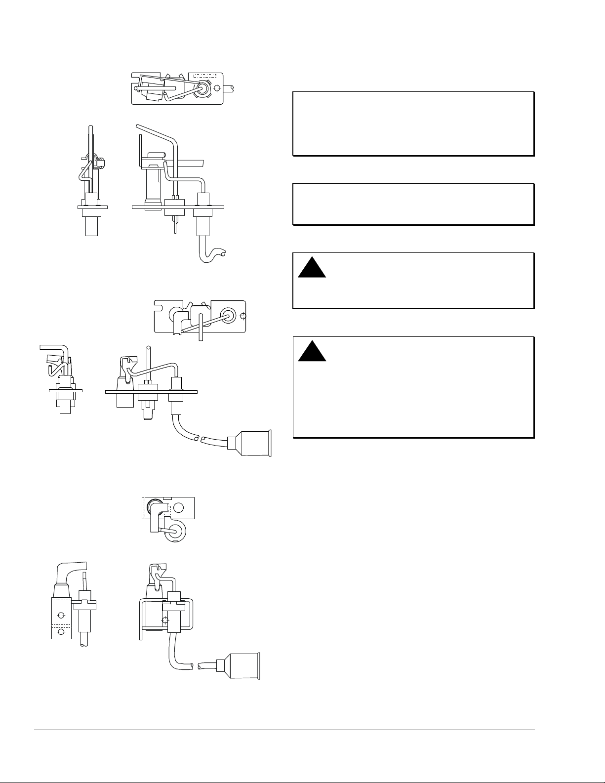
Side Views
Top View
J989EKW
Side Views
Figure 2: Q90BB-1 (J996DKW) Pilot Burner
Top View
J996DKW
Figure 1: Q90AA-1 (J989EKW) Pilot Burner
© 2012 Johnson Controls, Inc. 1
Part No. BASO-INS-Q90, Rev. A www.baso.com
Page 2
Top View
Installation
IMPORTANT: Only qualified personnel should
install or service Johnson Controls products. These
instructions are a guide for such personnel. Carefully
follow all instructions in this document and all
instructions for the appliance.
IMPORTANT: Make all gas installations in
accordance with applicable local, national, and
regional regulations.
Side Views
J986HXW
Figure 3: Q90CC-1 (J986HXW) Pilot Burner
Top View
Side Views
J990HHW/J993HHW
Figure 4: Q90DD-1 (J993HHW) Pilot Burner
Q90DD-2 (J990HHW) Pilot Burner
!
CAUTION: Risk of Electrical Shock.
Disconnect power supply before making electrical
connections to avoid electrical shock.
!
WARNING: Risk of Explosion or Fire.
Shut off the gas supply at the main manual shutoff
valve before installing or servicing the control.
Failure to shut off the gas supply can result in the
release of gas during installation or servicing, which
can lead to an explosion or fire, and may result in
severe personal injury or death.
To install the Q90 pilot burner assembly:
1. Shut off powe r to the applia nce.
2. Turn off the g as at the main manual shutoff valve
adjacent to the appliance.
3. Disco nnect the pilot tubing from the existing pilot
Top View
4. Disconnect the high voltage cable (from the spark
5. Remove the pilot burner assembly mounting
6. Remove the existing pilot burner assembly and
Side Views
J995DHW
Figure 5: Q90EA-1 (J995DHW) Pilot Burner
7. Install the Q9 0 pilot burner assembly using the
8. Re connect the pilot tubing to the Q90 pilot burner
2 Q90 Series Pilot Burner Assembly Kit Installation Instructions
burner assembly.
transformer) and sensor cable (from Terminal 4)
on the ignition control.
screws.
discard.
screws that were removed in Step 3. Ensure the
screws are tight and secure.
assembly.
Page 3
9. Con nect the sensor cable to the male spade
connector on the pilot burner sensing probe and
Terminal 4 on the ignition control.
10. Connect the high voltage on the pilot burner
assembly to the spark transformer on the ignition
control.
!
WARNING: Risk of Explosion or Fire.
Verify that there are no gas leaks by testing with
appropriate equipment. Never use a match or lighter
to test for the presence of gas. Failure to test
properly can lead to an explosion or fire and may
result in severe personal injury or death.
11. Check for leakage.
a. Shut off the gas at the main manual shutoff
valve and open the pressure connection
between the manual shutoff valve and the gas
valve.
b. Connect air tubing with a maximum pressure
of 1 1/2 times the valve’s maximum operating
pressure (as indicated on the valve) to the
opened pressure connection.
c. Paint all valve body and pilot tubing
connections with a rich soap and water
solution.
If bubbles occur, this indicates a leak. To stop
a leak, tighten joints and connections. Replace
the part if the leak cannot be stopped.
If bubbles do not occur, remove the air tubing
and close the pressure connection.
12. Perform the Checkout section before leaving the
installation.
Setup and Adjustments
Checkout
!
WARNING: Risk of Explosion or Fire.
Follow this or an equivalent checkout procedure
after installation. Before leaving the installation,
verify that the gas valve functions properly and that
the system has no gas leaks. Gas leaks can lead to
an explosion or fire, and may result in severe
personal injury or death.
Make sure all components are functioning properly by
performing the following test.
1. Test all joints and connections for leaks with a
soap solution.
2. Clo se the main upstream shutoff valve and wait
at least 5 minutes for unburned gas to escape
from the appliance, and then reopen the shutoff
valve.
3. Turn o n the main electrical power switch and
close the thermostat contacts. The appliance
should operate in accordance with the
manufacturer’s specified sequence of operation.
4. Turn the the rmostat to a low setting to open the
contacts. All burner flames should extinguish.
5. Observe at le ast three complete operating cycles
to make sure that all components are functioning
properly.
6. Return the thermo stat to a normal temperature
setting before leaving the installation.
Repairs and Replacement
Field repairs must not be made to the Q90 pilot
assembly kit. Any attempt to repair this assembly voids
the manufacturer’s warranty. For a replacement pilot
assembly kit or accessories, contact the original
equipment manufacturer or the nearest Johnson
Controls distributor.
Q90 Series Pilot Burner Assembly Kit Installation Instructions 3
Page 4

Technical Specifications
Product
Material
Maximum Temperature
Ratings
Flame Sensor Lead
Agency Listings
Specifications Standards
Performance specifications are nominal and conform to acceptable industry standards. All agency certification of BASO products is performed
under dry and controlled indoor environmental conditions. Use of BASO products beyond these conditions is not recommended and may void
the warranty. Product must be protected if exposed to water (dripping, spraying, rain, etc.) or other harsh environments. The original
equipment manufacturer or end user is responsible for the correct application of BASO products. Consult BASO Gas Products LLC for
questionable applications. BASO Gas Products LLC shall not be liable for damages or product malfunctions resulting from misapplication or
misuse of its products.
Refer to the J Series Pilot Burners/Y90 Series Inlet Fitting Product Bulletin (BASO-PB-PILOTS/Y90) for necessary information on operating
and performance specifications for this product.
Q90 Series Pilot Burner Assembly Kit
Spark Electrode Rod 446 Stainless
Mounting Bracket Plated Steel
Flame Sensor Kanthal D or Hoskins 815
Pilot Tip 430 Stainless
Pilot Body Plated Steel
Inlet Tip Aluminum
Inlet Body Brass
Ceramic Steatite
Ignition Cable 18 AWG, UL Wire Style 3257
Spark Electrode Rod
Mounting Bracket
Sensor
Pilot Tip
Pilot Body
Inlet Tip
Inlet Body
Ceramic
Ignition Cable
1500°F (816°C)
825°F (441°C)
1800°F (982°C)
1500°F (816°C)
825°F (441°C)
635°F (335°C)
750°F (399°C)
1000°F (538°C)
482°F (250°C)
Standard High Temperature
Gauge 18 AWG 18 AWG
Maximum Temperature Rating
302°F (150°C) 482°F (250°C)
UL Wire Style Style 3212 Style 3252
Pilot Burner CSA Certificate Number 229521-1656071
ANSI Z21.20
CAN1-6.4
CAN/CSA-C22.2 No. 199-M89
1007 South 12th Street
PO Box 170
Watertown, WI 53094 www.baso.com
1-877-227-6427 (1-877-BASOGAS) Printed in U.S.A
4 Q90 Series Pilot Burner Assembly Kit Installation Instructions
 Loading...