

Page 1
Installation Instructions
Issue Date January 20, 2015
© 2015 BASO Gas Products. 1
Part No. BASO-INS-L62GB, Rev. C www.baso.com
L62GB BASO® Safety Shutoff Device
Installation
IMPORTANT: Only qualified personnel should
install or service BASO® Gas Products. These
instructions are a guide for such personnel. Carefully
follow all instructions in this document and all
instructions for the appliance.
!
WARNING: Risk of Explosion or Fire.
Shut off the gas supply at the main manual shutoff
valve before installing or servicing the L62GB.
Failure to shut of the gas supply can result in the
release of gas during installation or servicing, which
can lead to an explosion or fire, and may result in
severe personal injury or death.
!
CAUTION: Risk of Electric Shock.
Disconnect power supply before making electrical
connections to avoid electric shock.
IMPORTANT: Make all gas installations in
accordance with applicable local, national, and
regional regulations.
To install the L62GB.
1. Turn off power to the appliance.
2. Turn off gas at the main manual shutoff valve
adjacent to the appliance.
3. Remove the L62GB cover by loosening the screw
on the front of the device (not the brass hex nut).
IMPORTANT: Do not loosen or tighten the
brass hex nut that fastens the brass terminal
bushing to the plastic switch housing. The machined
flats on the terminal bushing must be parallel to the
flats on the switch housing. If not, the switch power
unit may distort and cause the safety switch to fail.
4. Mount the L62GB in any convenient position using
the mounting holes in the back of the case.
5. Push the circuit wires through the conduit opening
on the side of the device, strip the ends of the
wires just enough to put the bare wire under the
terminal screws, and attach them to the two wire
terminals.
!
WARNING: Risk of Explosion or Fire.
Do not attach both wires to one terminal on the
L62GB. Doing so bypasses and eliminates all safety
features provided by the L62GB, can lead to an
explosion or fire, and may result in severe personal
injury or death.
!
WARNING: Risk of Explosion or Fire.
Verify that this device is wired in series electrically
with thermostats and other appliance operating
controls. Wiring the device in parallel with such
controls will defeat the safety features of this device
and may result in severe personal injury or death.
6. Replace the cover. Do not loosen the brass hex
nut.
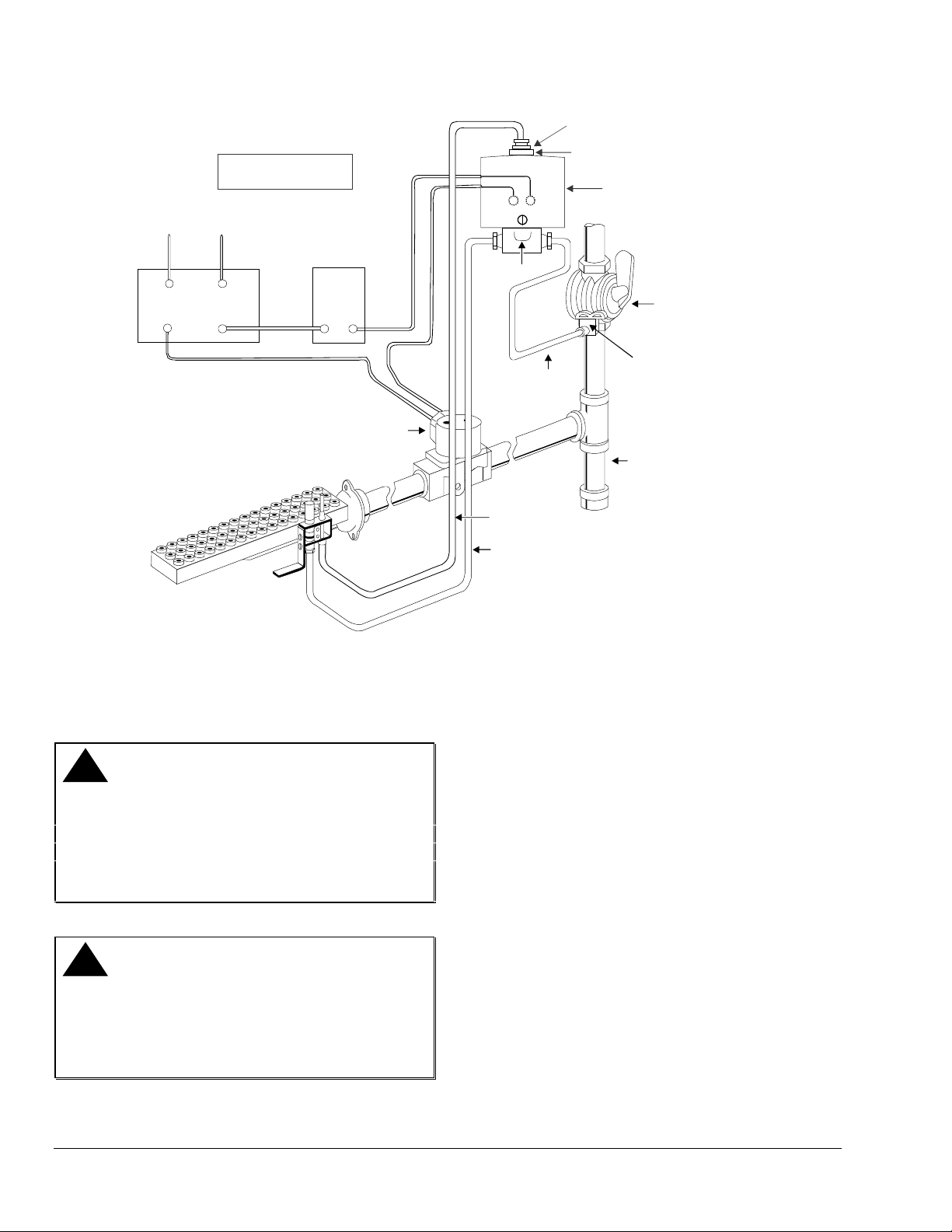
7. Connect the pilot burner orifice fitting to the pilot
outlet on the L62GB with 1/4 in. outside diameter
tubing, and connect the pilot gas inlet with the gas
manifold upstream from the automatic valve.
Note: The pilot line connection is bidirectional as
indicated by the arrows pointing in either direction.
This provides the option of connecting the pilot gas
inlet and outlet in either position.
Attach the thermocouple securely to the pilot burner,
and screw the terminal end to the BASO® power unit
terminal on the L62GB. Make sure that this
connection is clean. Tighten the thermocouple lead
nut finger tight plus a maximum of 1/8 turn. Do not
overtighten.
Page 2
2 L62GB BASO Safety Shutoff Device Installation Instructions
Red Lever
Transformer
Power Source
Thermostat
"X”
"X”
Main Manual
Shutoff Valve
(”A” Valve)
L62GB BASO
Safety Shutoff Device
Pilot Valve
(“B” Valve)
“X” indicates possible
locations for other controls.
Thermocouple
Lead
Pilot Gas
Outlet
Power Unit
Terminal
76.2 mm (3 in.)
Sediment
Trap
Pilot Gas
Inlet
Basotrol
Valve
Do not loosen brass hex nut.
Must be tight to maintain continuity.
Figure 1: Typical L62GB Installation
Setup and Adjustments
Checkout
!
WARNING: Risk of Explosion or Fire.
Follow this or an equivalent checkout procedure
after installation. Before leaving the installation,
verify that the L62GB functions properly and that the
system has no gas leaks. Gas leaks can lead to an
explosion or fire, and may result in severe personal
injury or death.
!
WARNING: Risk of Explosion or Fire.
Verify that there are no gas leaks by testing with
appropriate equipment. Never use a match or lighter
to test for the presence of gas. Failure to test
properly can lead to an explosion or fire and may
result in severe personal injury or death.
Make sure all components are functioning properly by
performing the following test:
1. Test all joints and connections for leaks with a
soap solution.
2. Set the thermostat to the lowest setting.
3. Close the main manual shutoff valve (A valve) and
the pilot valve (B valve [see Figure 1]) and wait at
least 5 minutes for unburned gas to escape from
the appliance.
4. Reopen the B valve, push down the red lever and
light the pilot burner. Continue to hold down the
red lever for approximately 30 seconds.
5. Open the A valve. The main burner ignites from
the pilot burner when the thermostat calls for heat.
6. Disconnect the thermocouple from the L62GB.
The main valve should close immediately. If it
does not close, check for wiring errors. Reconnect
the thermocouple to the L62GB when it is
operating correctly.
Page 3
L62GB BASO Safety Shutoff Device Installation Instructions 3
7. Make sure the brass hex nut is tight for good
continuity. Do not over tighten.
8. Check the millivoltage output of the thermocouple
and milliampere dropout range at the BASO power
unit terminal to see that they meet the values in
Table 1 and Table 2. Step-by-step procedures for
these checks are included with the Y99AB BASO
Test Kit.
9. Relight the pilot.
10. Observe at least three complete operating cycles
to make sure that all components are functioning
correctly.
11. Reset the thermostat to a normal temperature
setting before leaving the installation.
Repairs and Replacement
Field repairs must not be made to the L62GB safety
shutoff device. If the thermocouple meets the output
listed in Table 1 and the valve does not function,
replace the entire device. Any attempt to repair this
assembly voids the manufacturer’s warranty. For a
replacement safety shutoff device, contact the nearest
BASO Gas Productsdistributor.
Check the millivoltage output of the thermocouple and
milliampere dropout range at the BASO power unit
terminal to see that they meet the values in Table 1
and Table 2. If the readings do not meet these values,
replace the thermocouple and/or the safety shutoff
device.
Table 1: Thermocouple Output
Thermocouple
mV Range
Lead Type
Turn
Down
Normal
Not Less
Than
K15
4 mV
20-28
15
K16
4 mV
25-35
17
K17
4 mV
30-40
25
K19
4 mV
25-35
17
Note: In high temperature locations, use K15 or
K16 Series
Table 2: L62GB Dropout Range
mA Range of Power Unit Assembly
Low
High
100
300
Pilot Servicing
If pilot flame problems occur, check the following:
If the pilot flame burns yellow, it may be due to dirt
or lint covering the lower portion of the pilot
burner. Remove dirt and lint using a soft brush or
a vacuum cleaner.
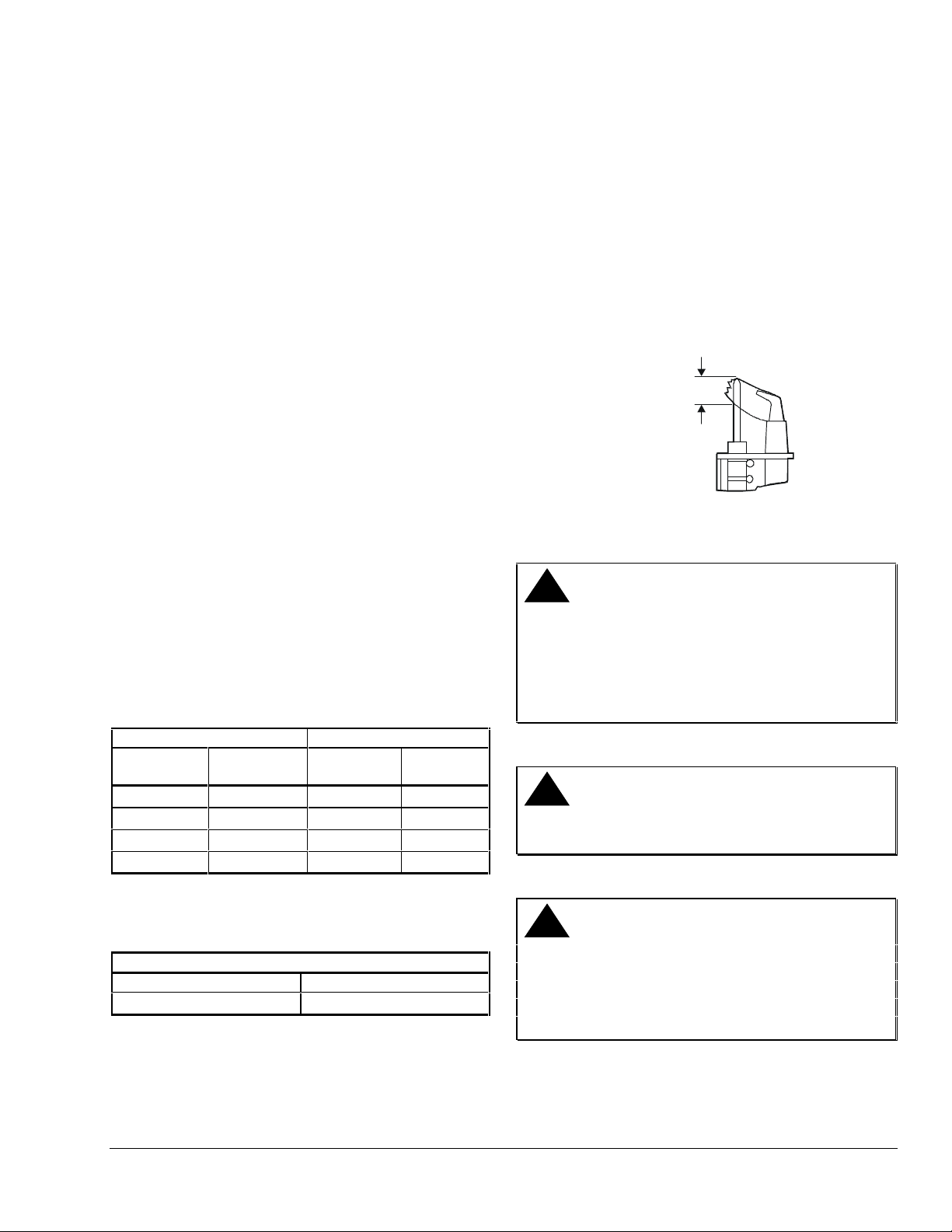
A flame approximately 0.5 in. (12.7 mm) high must
surround the thermocouple tip (see Figure 2).
Because this is an electrical connection, the
thermocouple lead connection to the BASO power
unit must be clean and free of grease.
Approximately
1/2 in. (12.7 mm)
Figure 2: Flame Position
Replacement Procedure
!
WARNING: Risk of Explosion or Fire.
Shut off the gas supply at the main manual shutoff
valve before installing or servicing the L62GB.
Failure to shut off the gas supply can result in the
release of gas during installation or servicing, which
can lead to an explosion or fire, and may result in
severe personal injury or death.
!
CAUTION: Risk of Electrical Shock.
Disconnect power supply before making electrical
connections to avoid electrical shock.
!
WARNING: Risk of Explosion, Fire, or
Electric Shock. Label all wires before they are
disconnected when replacing the L62GB. Wiring
errors can cause improper or dangerous operation
and may result in an electric shock, fire, or explosion
leading to severe personal injury or death.
Page 4
4 L62GB BASO Safety Shutoff Device Installation Instructions
When necessary, replace the safety shutoff device as
follows:
1. Turn off power to the appliance.
2. Close the main manual shutoff valve and the pilot
valve.
3. Disconnect the thermocouple lead from the safety
shutoff device.
4. Remove the cover from the old safety shutoff
device (not the brass hex nut).
5. Disconnect and label the wires from the two wire
terminals and remove the device from the
appliance.
6. Remove the new L62GB cover by loosening the
screw on the front of the device (not the brass hex
nut).
Note: The L62GB may be mounted in any position
by the mounting holes in the back of the case or by
using the universal mounting plate supplied with the
device.
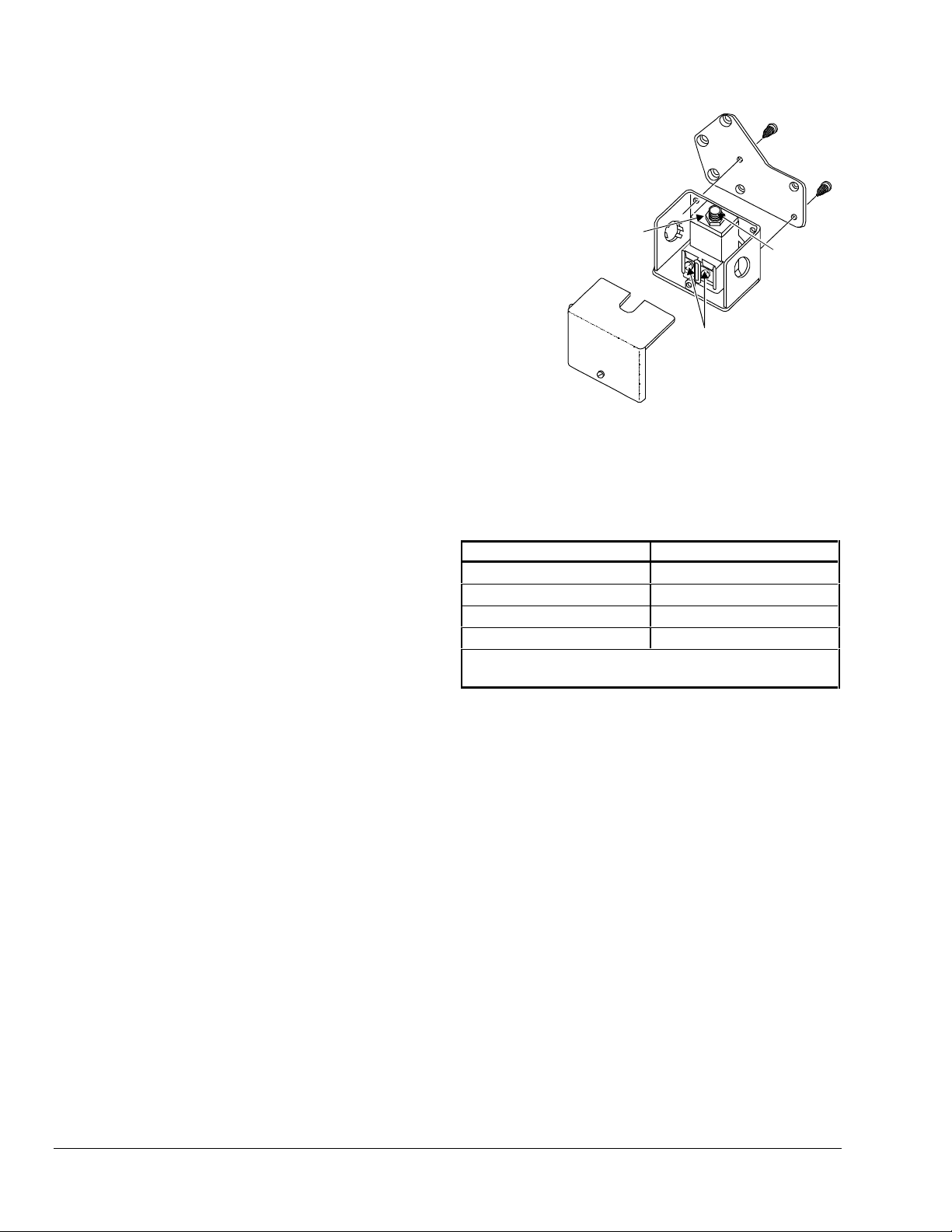
7. Attach the universal mounting plate to the device
when required (see Figure 3). Secure the
mounting plate to the switch case with the sheet
metal screws provided. The mounting plate is not
required for exact replacements.
1
2
4
5
3
Universal
Mounting Plate
BASO
Power Unit
Terminal
Wire Terminals
L62GB-3
Cover
Do not loosen brass hex nut.
Must be tight to maintain continuity.
Figure 3: L62GB-3 Mounting
8. Mount the L62GB-3 using the holes in the
universal mounting plate that match the mounting
holes for the device being replaced (see Table 3).
Table 3: Mounting Guide
Switch Being Replaced
Use Holes Numbered
PENN® (BASO) L62EA
1, 2, 3
PENN (BASO) L62GB-1
Plate Not Required
Honeywell® C591A
4, 5
ITT/General A100G653
4, 5
Note: Remove the L62GB cover for access to Holes 3
and 5.
9. Refer to Steps 5 through 8 in the Installation
section to complete the installation.
10. Perform the Checkout procedure before leaving
the installation.
Page 5
L62GB BASO Safety Shutoff Device Installation Instructions 5
Technical Specifications
Product
L62GB BASO Safety Shutoff Device
100% Shutoff
Yes
Conduit Opening
2 (1 plugged)
Switch Contacts
Electrical Specifications
24/25 VAC
125 VAC
250 VAC
*
8 A
4 A
Ambient Temperature
Range
-40 to 175F (-40 to 79C)
Reset
Manual
Switch Action
SPST
Type of Gas
Natural, Liquefied Petroleum (LP), manufactured, mixed, or LP gas-air mixtures
Rated Inlet Pressure
0.5 psi (35 mbar)
Packaging
Bulk pack supplied to original equipment manufacturer (individual pack optional). L62GB-3
supplied as individual pack only.
Bulk Pack Quantity
30
Weight
32 lb (14.5 kg)
Agency Listings
CSA Certificate Number 229521-1656085
Specification Standards
ANSI Standard Z21.20
CAN1-6.4
* Switch can be used on 24/25 VAC installation.
Performance specifications are nominal and conform to acceptable industry standards. All agency certification of BASO products is performed
under dry and controlled indoor environmental conditions. Use of BASO products beyond these conditions is not recommended and may void
the warranty. Product must be protected if exposed to water (dripping, spraying, rain, etc.) or other harsh environments. The original
equipment manufacturer or end user is responsible for the correct application of BASO products. Consult BASO Gas Products LLC for
questionable applications. BASO Gas Products LLC shall not be liable for damages or product malfunctions resulting from misapplication or
misuse of its products.
Refer to the L61, L62 Series BASO Safety Shutoff Device Product Bulletin (BASO-PB-L61/L62) for necessary information on operating and
performance specifications of this product.
1007 South 12th Street
PO Box 170
Watertown, WI 53094 www.baso.com
1-877-227-6427 (1-877-BASOGAS) Published in U.S.A.
 Loading...