

Page 1
Installation Instructions
Issue Date February 22, 2013
H15 Series BASO® 100% Shutoff,
Automatic Pilot Valve
Application
The H15 Series pilot valves provide safe lighting and
complete shutoff of pilot and main burner gas on a
variety of domestic and commercial gas burning
equipment. Applications include room heaters, wall
heaters, unit heaters, central heating equipment, crop
dryers, dish washing machines, industrial ovens, and
degreasing equipment.
IMPORTANT: Verify that the valve is installed
only in applications where the specified maximum
ambient (surface) temperature and maximum
operating pressures do not exceed the limits in the
Technical Specifications section.
Installation
IMPORTANT: Only qualified personnel should
install or service BASO Gas Products products.
These instructions are a guide for such personnel.
Carefully follow all instructions in this document and
all instructions for the appliance.
IMPORTANT: Make all gas installations in
accordance with applicable local, national, and
regional regulations.
!
CAUTION: Risk of Electrical Shock.
Disconnect power supply before making electrical
connections to avoid electrical shock
Note: In applications that do not require electrical
power, disregard the above caution.
!
WARNING: Risk of Explosion or Fire.
Shut off the gas supply at the main manual shutoff
valve before installing or servicing the H15. Failure
to shut off the gas supply can result in the release of
gas during installation or servicing, which can lead to
an explosion or fire, and may result in severe
personal injury or death.
To install the H15 valve:
1. Shut off power to the appliance (if applicable).
2. Shut off the gas at the main manual shutoff valve.
3. Ensure that the main gas flow through the gas
valve body must be in the direction indicated by
either “IN” and “OUT” or the arrow on the valve
body. If the valve is installed with the gas flow in
the opposite direction of the arrow, leakage can
occur.
IMPORTANT: Do not use a wrench on any
surface other than the casting flats provided at the
inlet and outlet ends of the valve body. The H15 may
be damaged in the mounting process if a wrench is
used on any other surface. Using a wrench
incorrectly may void the warranty.
4. Mount the valve to the pipework. The H15 valve
may be mounted in any convenient position. Use
an approved pipe joint sealing compound on the
male threads before assembly. Remove excess
compound after mounting the valve to the
pipework. Threads of the pipe and nipples must
be smooth and free of tears and burrs. Steam
clean all piping to remove foreign substances
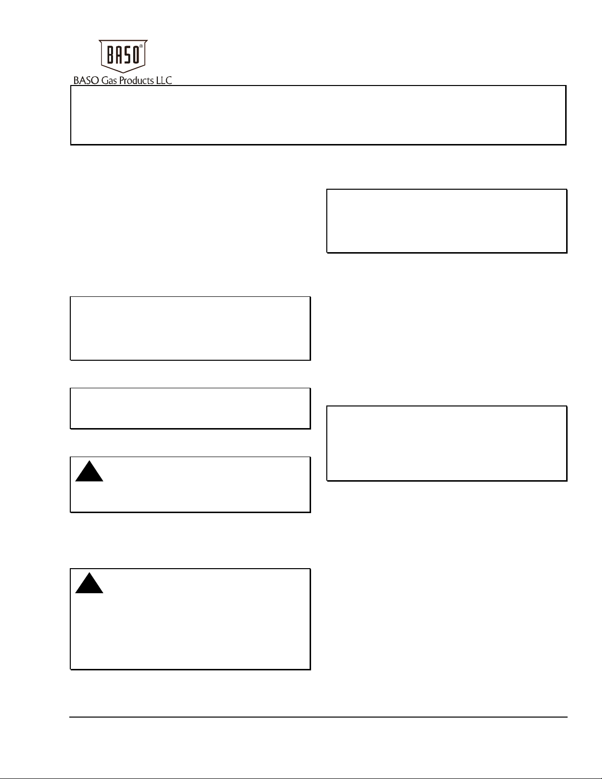
such as cutting oil or thread chips. A sediment
trap should also be installed in accordance with
the National Fuel Gas Code (ANSI Z223.1). (See
Figure 1 and Figure 2.)
5. Attach the thermocouple securely to the pilot
burner, and screw the terminal end to the BASO®
power unit terminal on the valve. Make sure this
connection is clean. Tighten the thermocouple
lead nut finger tight, plus a maximum of 1/8 turn.
Do not overtighten.
© 2013 BASO Gas Products
Part No. BASO-INS-H15, Rev. E www.baso.com
1
Page 2
6. Pilot gas connections.
a. Internal Pilot Gas Valve Models receive pilot
gas internally from the valve body.
Note: Pilot gas flow comes out of either gas
valve top housing ports.
On internal pilot gas valve models, plumb the
pilot burner fitting to either of the pilot gas
ports on the valve. Plug the unused pilot gas
port on the gas valve. See Figure 1 and
Figure 2.
b. External Pilot Gas Valve Models receive
pilot gas from an external gas source.
!
WARNING: Risk of Explosion or Fire.
Verify that there are no gas leaks by testing with
appropriate equipment. Never use a match or lighter
to test for the presence of gas. Failure to test
properly can lead to an explosion or fire and may
result in severe personal injury or death.
7. Check for leakage.
a. Shut off the gas at the main manual shutoff
valve and open the pressure connection
between the manual shutoff valve and the
H15 valve.
Note: Pilot gas flow through the gas valve top
housing can be in either direction as indicated
by the arrows.
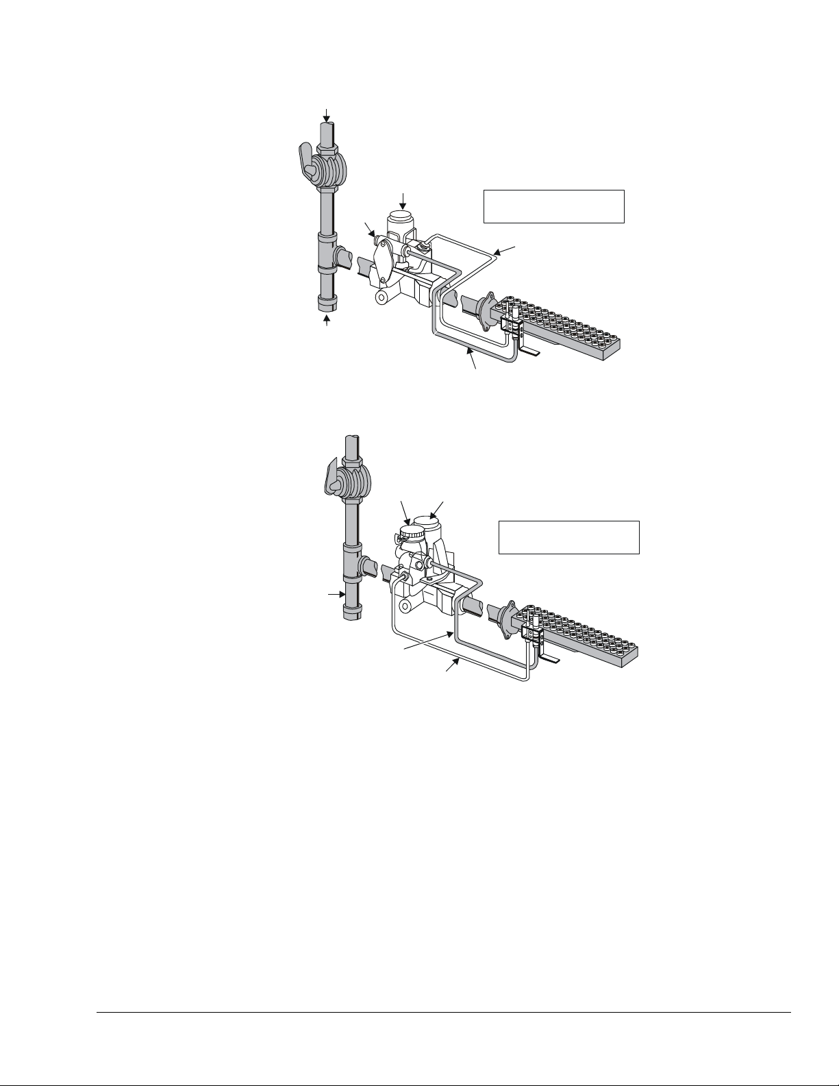
On external pilot gas valves models, plumb
the pilot gas line from an external gas source
to either pilot gas port on the gas valve. Plumb
the other pilot gas port to the pilot burner
fitting. See Figure 3.
c. Gas valve models with black arrows are
limited to applications up to 175˚F (80˚C).
d. Gas valve models with red arrows are limited
to applications up to 300˚F (150˚C).
!
WARNING: Risk of Explosion or Fire.
Never connect an external gas line to an internal
pilot gas model. Pilot gas would flow freely in one
port and out the other, which could lead to an
explosion or fire and may result in severe personal
injury or death.
b. Connect air tubing with a maximum pressure
of 1-1/2 times the valve’s maximum
operating pressure (as indicated on the
valve) to the opened pressure connection.
c. Paint all valve body connections with a rich
soap and water solution.
If bubbles occur, this is an indication of a
leak. To stop a leak, tighten joints and
connections. Replace the part if the leak
cannot be stopped.
If bubbles do not occur, remove the air
tubing and close the pressure connection.
8. Perform the Checkout before leaving the
installation.
2 H15 Series BASO 100% Shutoff Automatic Pilot Valve Installation Instructions
Page 3
Gas Suppl
y
X
X
X
Shutoff
Valve
3 in. (76.2 mm)
Sediment Trap
Plug
X
Reset Button
indicates possible
locations f or other contr ol s.
Thermocouple
X
Pilot Burner
Gas Line
Lead
Figure 1: Typical Installation of an H15 Valve with Internal Pilot Gas Flow (Models H15_A and H15_B)
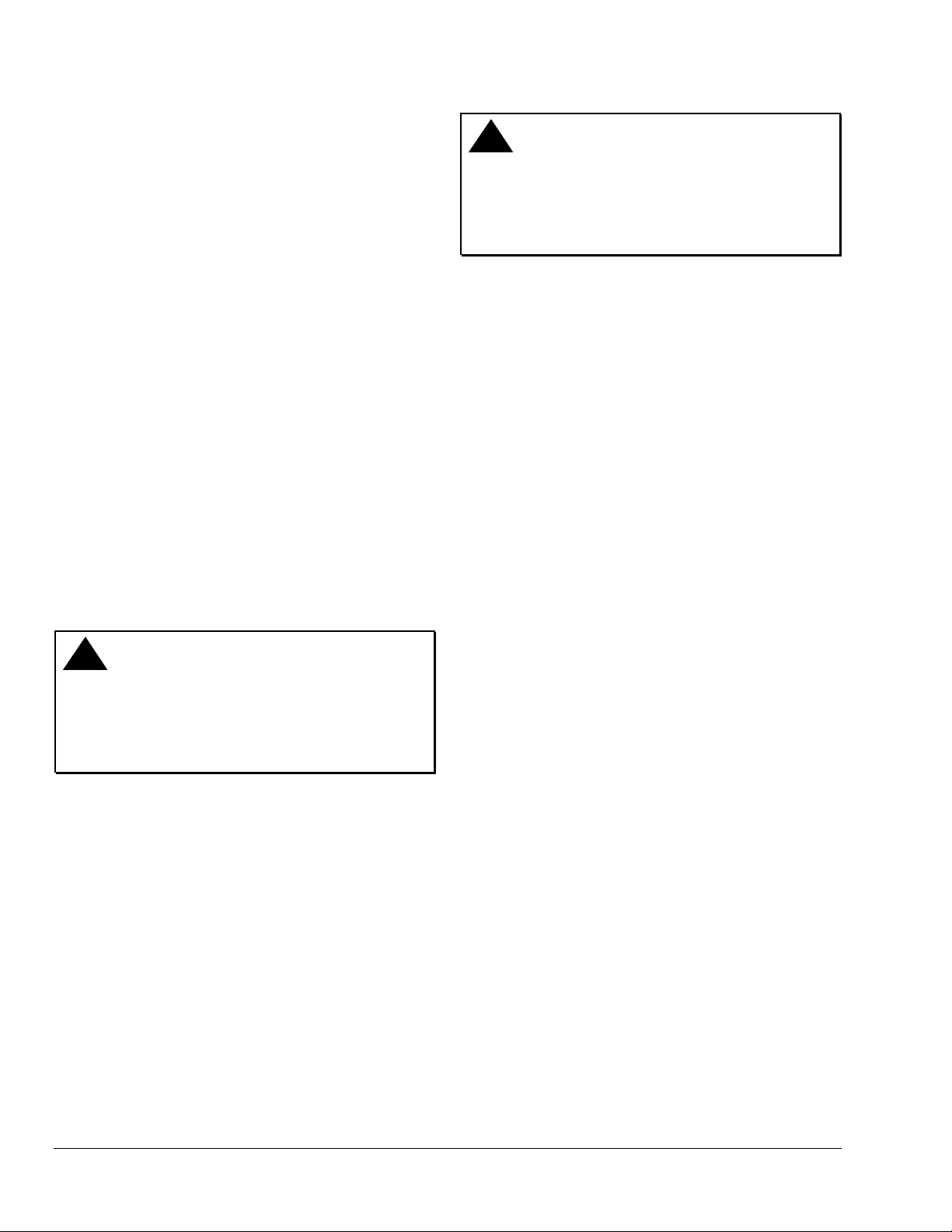
B
Shutoff
Valve
Rotor
X
Valve
Reset
Button
indicates po ssible
locations f or other contro ls .
3 in. (72.6 m m)
Sediment Trap
Pilot Burner
Gas Line
Thermocouple
Lead
Figure 2: Typical Installation of an H15 Valve with Internal Pilot Gas Flow and Rotor “B” Valve
(Models H15_H)
H15 Series BASO 100% Shutoff Automatic Pilot Valve Installation Instructions 3
Page 4
y
Shutoff
X
Valve
Gas Suppl
Optional
Valve
B
Reset Button
indicates possible
locations f or other contr ol s.
X
X
3 in. (76.2 mm)
Sediment Trap
Pilot Burner
Gas Line
Thermocouple
Lead
Figure 3: Typical Installation of an H15 Valve with External Pilot Gas Flow (Models H15_Q and H15_R)
Setup and Adjustments
Checkout
!
WARNING: Risk of Explosion or Fire.
Follow this or an equivalent checkout procedure
after installation. Before leaving the installation,
verify that the gas valve functions properly and that
the system has no gas leaks. Gas leaks can lead to
an explosion or fire, and may result in severe
personal injury or death.
Make sure all components are functioning properly by
performing the following test.
1. Test all joints and connections for leaks with a
rich soap and water solution. If leaks occur, see
Step 6 in the Installation section.
2. Close the main upstream shutoff valve and the
B valve (applications with a B valve only) and
wait at least 5 minutes for unburned gas to
escape from the appliance, then reopen the
valves.
3. Push the reset button and light the pilot burner.
Continue to hold the reset button for
30 to 45 seconds or until the pilot remains
burning when the reset button is released.
4. Check the millivoltage output of the thermocouple
and the milliampere dropout range of the BASO
power unit to be sure they meet the values in
Table 1 and Table 2. Step-by-step procedures for
these checks are included with the Y99AB-4
BASO Test Kit Application Note
(Part No. 24-8711-838).
5. Observe at least three complete operating cycles
to make sure that all components are functioning
properly.
6. Reset the thermostat to the desired setting before
leaving the installation.
Table 1: Thermocouple Output
Thermocouple mV Range
Lead Type Turn
Down
K15
K16
K19
4 mV 20-28 15
4 mV 25-35 17
4 mV 25-35 17
Normal Not Less
Than
4 H15 Series BASO 100% Shutoff Automatic Pilot Valve Installation Instructions
Page 5
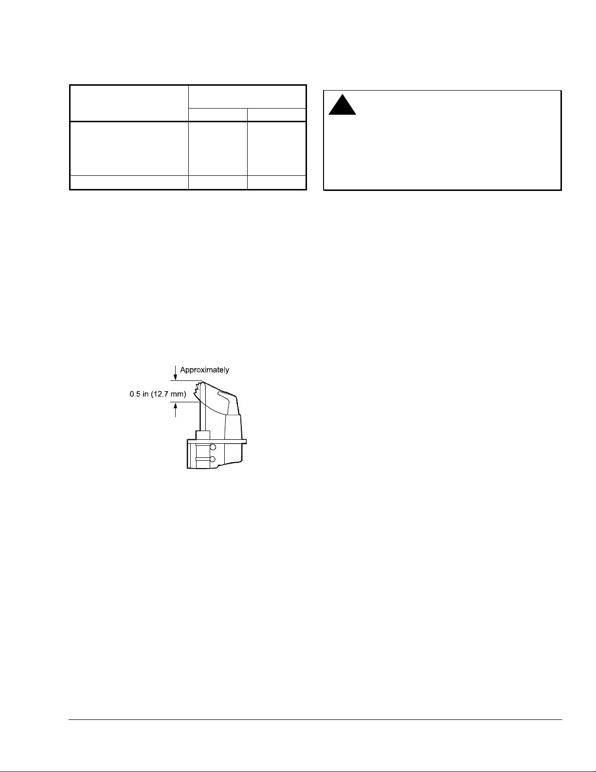
Table 2: Dropout Range
Series Number
H15AA, H15AB, H15AR,
H15CA, H15CB, H15CH,
H15CQ, H15DA, H15DB,
H15DH, H15DQ, H15HQ,
H15HR, H15QB, H15QR
H15EQ, H15FA, H15FQ
Pilot Servicing
If pilot flame problems occur, check the following:
• If the pilot flame burns yellow, it may be due to dirt
or lint covering the lower portion of the pilot
burner. Remove this using a soft brush or a
vacuum.
• A flame approximately 1/2 in. (12.7 mm) high must
surround the thermocouple tip (Figure 4).
• Because this is an electrical connection, the
thermocouple lead connection to the BASO power
unit must be clean and free of grease.
mA Range of
Power Unit Assembly
Low High
100 300
50 165
Repairs and Replacement
!
WARNING: Risk of Explosion or Fire.
Shut off the gas supply at the main manual shutoff
valve before installing or servicing the H15. Failure
to shut off the gas supply can result in the release of
gas during installation or servicing, which can lead to
an explosion or fire, and may result in severe
personal injury or death.
Field repairs must not be made to the H15 valve. If
the thermocouple meets the output listed in Table 1
and the valve does not function, replace the entire
valve. Any attempt to repair this assembly voids the
manufacturer’s warranty. For a replacement valve,
contact the original equipment manufacturer or the
nearest BASO Gas Products distributor.
Figure 4: Flame Position
H15 Series BASO 100% Shutoff Automatic Pilot Valve Installation Instructions 5
Page 6

Technical Specifications
Product
Rated Inlet Pressure
Valve Body
Permissible Ambient
(Surface) Temperature
Recommended
Thermocouple Lead
Lengths
Inlet and Outlet Body
Connections
Valve Torsion Group
Gas Valve Classification
Types of Gas
Packaging
Bulk Pack Quantity
Bulk Pack Weight
Agency Listing
Specification Standards
H15 Series BASO 100% Shutoff, Automatic Pilot Valve
0.5 psi (35 mbar [3.5 kPa])
Aluminum
-30 to 175°F (-34 to 79°C) models without rotor B valve
32 to 175°F (0 to 79°C) models with rotor B valve
32 to 300°F (0 to 149°C) H15_B and H15_R models only
K15: 12 to 48 in. (305 to 1,220 mm)
K16: 12 to 72 in. (305 to 1,830 mm)
K19: 18 to 72 in. (457 to 1,830 mm)
1/4, 3/8, 1/2, 3/4, or 1 in. NPT
Group 2 (EN 125)
Class B (EN 125)
Natural, Liquefied Petroleum (LP), and LP gas-air mixtures
Bulk pack supplied to original equipment manufacturer (individual pack option al)
32 and 40 (depending on valve size)
24 to 42 lb (11 to 19 kg)
CSA Certificate Number 229521-1656080
Australian Gas Association Certificate Number 4236 (Specific models without rotor valve only)
AGA Class 1, Valve Type Flame Safeguard (excludes H15Q_ and H15_B)
EC Type Examination Certificate Number E0485 (excludes models with rotor “B” valve, H15E_,
and H15Q_)
UL File Number MH2926 (H15CA, DA, and CH models only)
ANSI Z21.20, CAN1-6.4
ANSI Z21.21, CSA 6.5
ANSI Z21.78, CSA 6.20
AS 4620
EN 125
UL Standard 372
Performance specifications are nominal and conform to acceptable industry standards. All agency certification of BASO products is performed
under dry and controlled indoor environmental conditions. Use of BASO products beyond these conditions is not recommended and may void
the warranty. Product must be protected if exposed to water (dripping, spraying, rain, etc.) or other harsh environments. The original
equipment manufacturer or end user is responsible for the correct application of BASO products. Consult BASO Gas Products LLC for
questionable applications. BASO Gas Products LLC shall not be liable for damages or product malfunctions resulting from misapplication or
misuse of its products.
Refer to the H15 Series BASO 100% Shutoff Automatic Pilot Valve Product Bulletin (BASO-PB-H15) for necessary information on operating
and performance specifications of this product.
1007 South 12th Street
PO Box 170
Watertown, WI 53094 www.baso.com
1-877-227-6427 (1-877-BASOGAS) Printed in U.S.A.
6 H15 Series BASO 100% Shutoff Automatic Pilot Valve Installation Instructions
 Loading...