

Installation Instructions
Issue Date September 17, 2008
G292 Series BASO® Dual Pilot Gas Valve
Installation
IMPORTANT: Only qualified personnel should
install or service BASO® Gas Products. These
instructions are a guide for such personnel. Carefully
follow all instructions in this document and all
instructions for the appliance.
To install the G292 valve:
1. Shut off the gas at the main manual shutoff valve.
2. When installing the valve on the manifold, ensure
that the gas flows through the valve body in the
direction indicated by the arrow on the valve body.
If the valve is installed with the gas flow in the
opposite direction of the arrow, leakage can occur.
IMPORTANT: Make all gas installations in
accordance with applicable local, national, and
regional regulations.
!
WARNING: Risk of Explosion or Fire.
Shut off the gas supply at the main manual shutoff
valve before installing or servicing the G292. Failure
to shut off the gas supply can result in the release of
gas during installation or servicing, which can lead to
an explosion or fire, and may result in severe
personal injury or death.
IMPORTANT: Verify that the valve is installed
only in applications where the specified maximum
ambient (surface) temperature and maximum
operating pressures will not exceed the limits in the
Technical Specifications section.
IMPORTANT: Do not use a wrench on any
surface other than the casting flats provided at the
inlet and outlet ends of the valve body. The G292
may be damaged in the mounting process if a
wrench is used on any other surface. Using a
wrench incorrectly may void the warranty.
3. Mount the valve to the pipework. The G292 valve
may be mounted in any convenient position. Use
an approved pipe joint sealing compound on the
male threads before assembly. Remove excess
compound after mounting the valve to the
pipework. Threads of the pipe and nipples must be
smooth and free of tears and burrs. Steam clean
all piping to remove foreign substances such as
cutting oil or thread chips. A sediment trap must
be installed in accordance with the National Fuel
Gas Code (ANSI Z223.1).
4. Attach a thermocouple securely to each pilot
burner, and screw the terminal end to each
BASO® power unit terminal on the valve. Make
sure these connections are clean. Tighten the
thermocouple lead nut finger tight, plus a
maximum of 1/8 turn. Do not overtighten.
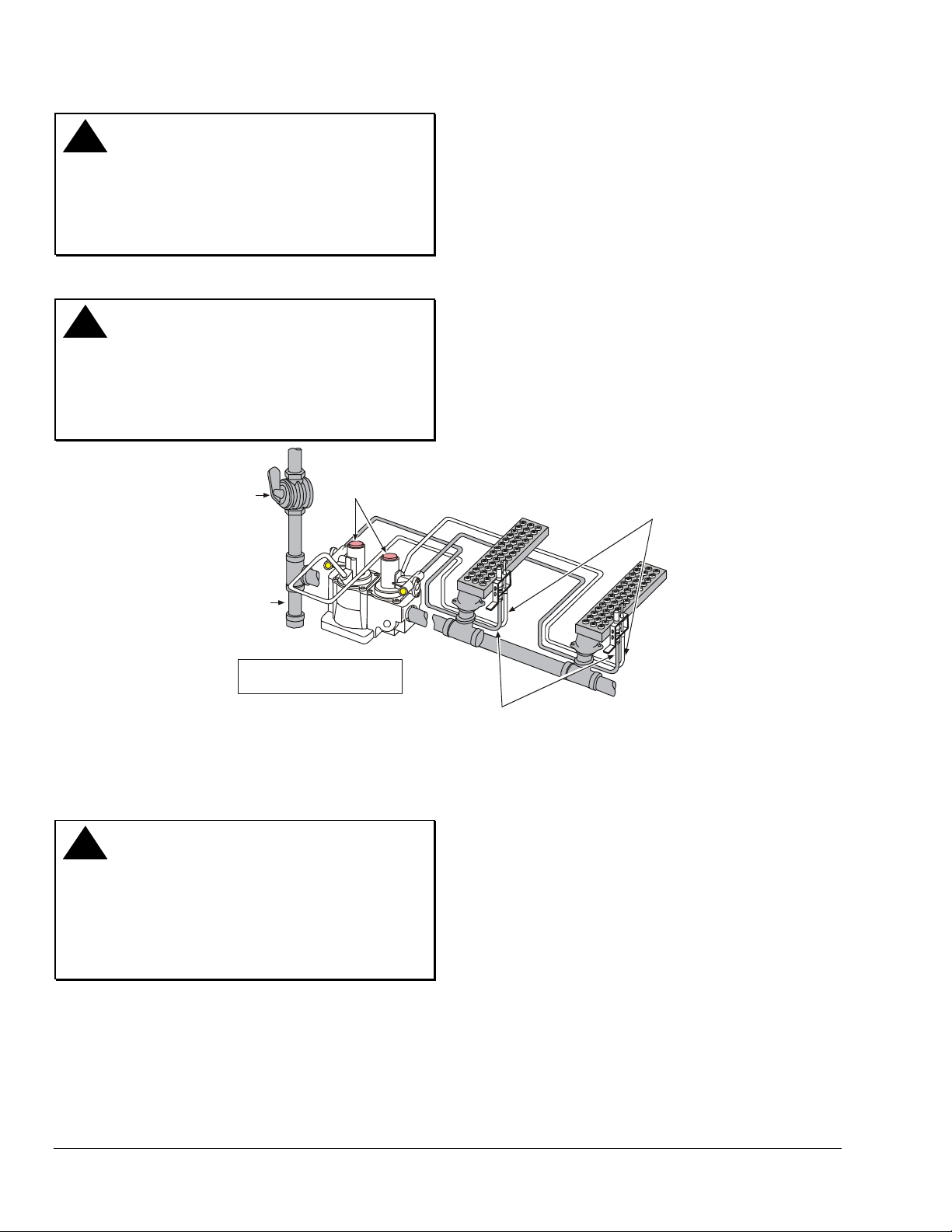
5. Pilot gas connections.
a. Internal Pilot Gas Valve Models receive pilot
gas internally from the valve body.
Note: Pilot gas flow comes out of either gas valve
top housing portx.
On internal pilot gas valve models, plumb the
pilot burner fitting to either of the pilot gas ports
on the valve. Plug the unused pilot gas port on
the gas valve. See Figure 1.
© 2008 BASO Gas Products 1
Part No. BASO-INS-G292, Rev.A www.baso.com
!
WARNING: Risk of Explosion or Fire.
Never connect an external gas line to an internal
pilot gas model. Pilot gas would flow freely in one
port and out the other, which could lead to an
explosion or fire and may result in severe personal
injury or death.
!
WARNING: Risk of Explosion or Fire.
Verify that there are no gas leaks by testing with
appropriate equipment. Never use a match or lighter
to test for the presence of gas. Failure to test
properly can lead to an explosion or fire, and may
result in severe personal injury or death.
6. Check for leakage:
a. Close the main upstream manual shutoff valve
and open the pressure connection between
the manual shutoff valve and the G292 valve.
b. Connect air tubing with a maximum pressure
of 1-1/2 times the valve’s maximum operating
pressure (as indicated on the valve) to the
opened pressure connection.
c. Paint all valve body connections with a rich
soap and water solution.
If bubbles occur, this is an indication of a leak.
To stop a leak, tighten joints and connections.
Replace the part if the leak cannot be stopped.
If bubbles do not occur, remove the air tubing
and close the pressure connection.
Shutoff
Valve
76.2 mm (3 in.)
Sediment Trap
X
locations for ot her controls.
Reset Buttons
X
indicates possible
Figure 1: Typical Installation for Internal Pilot Gas Flow
Setup and Adjustments
Checkout
!
WARNING: Risk of Explosion or Fire.
Follow this or an equivalent checkout procedure
after installation. Before leaving the installation,
verify that the gas valve functions properly and the
system has no gas leaks. Gas leaks can lead to an
explosion or fire, and may result in severe personal
injury or death.
Make sure all components are functioning properly by
performing the following test:
1. Open all upstream shutoff valves and test all joints
and connections of leaks with a soap solution.
2. Close the main upstream shutoff valve and wait at
least five minutes for unburned gas to escape from
the appliance, and then reopen the shutoff valve.
Thermocouple Leads
X
Pilot Burner Gas Lines
3. Push the reset button of the inlet (first) BASO
power unit and light the pilot burner (see Figure 1).
Continue to hold the reset button for 30 to
45 seconds or until the pilot remains burning when
the reset button is released.
4. Push the reset button of the outlet (second) BASO
power unit and light the pilot burner (see Figure 1).
Continue to hold the reset button for 30 to
45 seconds or until the pilot remains burning when
the reset button is released.
Note: If control thermostats for each burner are not
used, gas will flow to both main burners, igniting each.
5. Set the thermostat for the first main burner to the
highest setting. It should ignite from the pilot
burner.
2 G292 Series BASO Dual Pilot Gas Valve Installation Instructions

y
6. Set the thermostat for the second main burner to
the highest setting. It should ignite from the pilot
burner.
7. Set the thermostat for each burner to the lowest
setting. Both main burners should extinguish.
8. Extinguish the pilot burners by closing the main
upstream manual shutoff valve. Verify that the
valve drops out within 90 seconds.
9. Relight each pilot burner.
10. Check the millivoltage (mV) output of the
thermocouple and the milliampere (mA) dropout
range of each BASO power unit to ensure that
they meet the values listed in Table 1 and Table 2.
Step-by-step procedures for these checks are
included with the Y99AB-4 BASO Test Kit
Application Note.
11. Observe at least three complete operating cycles
to make sure that all components are functioning
properly.
12. Reset the thermostat to the desired setting before
leaving the installation.
Pilot Servicing
If pilot flame problems occur, check the following:
• If the pilot flame burns yellow, it may be due to dirt
or lint covering the lower portion of the pilot
burner. Remove this using a soft brush or a
vacuum.
• A flame approximately 1/2 in. (12.7 mm) high must
surround the thermocouple tip (see Figure 2).
• Because this is an electrical connection, the
thermocouple lead connection to the BASO power
unit must be clean and free of grease.
Approximatel
1/2 in. (12.7 mm)
Figure 2: Flame Position
Repairs and Replacement
Table 1: Thermocouple Output
Thermocouple mV Range
Lead
Type
K15
K16
K19
Turn
Down
4 mV 20-28 15
4 mV 25-35 17
4 mV 25-35 17
Normal
Not Less
Than
Table 2: Dropout Range
mA Range of Power Unit Assembly
Low High
100 300
!
WARNING: Risk of Explosion or Fire.
Shut off the gas supply at the main manual shutoff
valve before installing or servicing the G292. Failure
to shut off the gas supply can result in the release of
gas during installation or servicing, which can lead to
an explosion or fire, and may result in severe
personal injury or death.
Field repairs must not be made to the G292 valve. If
the thermocouple meets the output listed in Table 1
and the valve does not function, replace the entire
valve. Any attempt to repair this assembly voids the
manufacturer’s warranty. For a replacement valve,
contact the original equipment manufacturer or the
nearest BASO Gas Products distributor.
G292 Series BASO Dual Pilot Gas Valve Installation Instructions 3

Technical Specifications
Product
Maximum Operating
Pressure
Valve Body
Permissible Ambient
(Surface) Temperature
Recommended
Thermocouple Lead
Lengths
Body Connections
Types of Gas
Packaging
Bulk Pack Quantity
Bulk Pack Weight
Agency Listing
Specification Standards
G292 Series BASO Dual Pilot Gas Valve
0.5 psi (35 mbar)
Aluminum
-30 to 175°F (-34 to 79°C) without rotor B valve
32 to 175°F (0 to 79°C) with rotor B valve
K15: 12 to 48 in. (305 to 1,220 mm)
K16: 12 to 72 in. (305 to 1,830 mm)
K19: 18 to 72 in. (457 to 1,830 mm)
1/2 in. NPT Inlet x 1/2 in. NPT Outlet
1/2 in. NPT Inlet x 3/4 in. NPT Outlet
Natural, Liquefied Petroleum (LP), and LP gas-air mixtures
Bulk pack supplied to original equipment manufacturer (individual pack option al)
32
64 LB (29 kg)
CSA (AGA/CGA) Certificate Number 229521-1656050
ANSI Z21.78, CSA 6.20
UL Standard 372
Performance specifications are nominal and conform to acceptable industry standards. All agency certification of BASO products is performed
under dry and controlled indoor environmental conditions. Use of BASO products beyond these conditions is not recommended and may void
the warranty. Product must be protected if exposed to water (dripping, spraying, rain, etc.) or other harsh environments. The original
equipment manufacturer or end user is responsible for the correct application of BASO products. Consult BASO Gas Products LLC for
questionable applications. BASO Gas Products LLC shall not be liable for damages or product malfunctions resulting from misapplication or
misuse of its products.
Refer to the G292 Series BASO Dual Pilot Gas Valve Product Bulletin (BASO-PB-G292) for necessary information on operating and
performance specifications of this product.
1007 South 12th Street
PO Box 170
Watertown , WI 53094 www.baso.com
1-877-227-6427 (1-877-BASOGAS) Published in U.S.A.
4 G292 Series BASO Dual Pilot Gas Valve Installation Instructions
 Loading...