

Page 1
Installation Instructions
Issue Date June 12, 2014
E Series CE/AGA Approved
Intermittent Pilot Ignition Control
Application
The E Series CE/AGA Approved Intermittent Pilot
Ignition Control is a safety control designed for indirect
burner ignition and supervision, for use with all gases
and applicable to gas-fired appliances.
The E Series is a microprocessor based ignition
control. The microprocessor provides reliable software
control of all timings and operates a diagnostic
Light-Emitting Diode (LED). It provides ignition
sequence, flame monitoring, and safety shutoff for
boilers, furnaces and other gas-fired heating
appliances.
Installation
IMPORTANT: Only qualified personnel should
install or service BASO Gas Products®. These
instructions are a guide for such personnel. Carefully
follow all instructions for the appliance.
IMPORTANT: Make all gas installations in
accordance with applicable local, national, and
regional regulations.
Instructions for installing the pilot burner/igniter-sensor
are typically provided by the appliance manufacturer. It
is important to follow those instructions. If such
information is not included, refer to the Mounting
section.
Mounting
!
CAUTION: Risk of Electric Shock.
Disconnect power supply before making electrical
connections to avoid electric shock.
!
WARNING: Risk of Explosion or Fire.
Shut off the gas supply at the main manual shutoff
valve before installing or servicing the control.
Failure to shut off the gas supply can result in the
release of gas during installation or servicing, which
can lead to an explosion or fire, and may result in
severe personal injury or death.
!
WARNING: Risk of Explosion or Fire.
Do not install the control in an area that is exposed
to water (for example, dripping, spraying, rain). Do
not use the control if it has been exposed to water.
Exposure to water may cause malfunction and can
lead to an explosion or fire and may result in severe
personal injury or death.
IMPORTANT: This control is approved for use
with noise suppression (resistive) spark wires. If the
application has copper wire, it must be replaced.
© 2014 BASO Gas Products. 1
Part No. BASO-INS-ECA, Rev. A www.baso.com
IMPORTANT: Do not mount the control where
it can be exposed to direct infrared radiation from the
main burner or to temperatures in excess of the
maximum product temperature rating.
Replacement Instructions
Mark wires to existing control. Disconnect the wires
and remove the existing control.
The control is not position sensitive. It may be
mounted horizontally or vertically with two #6 sheet
metal or machine screws.
Page 2
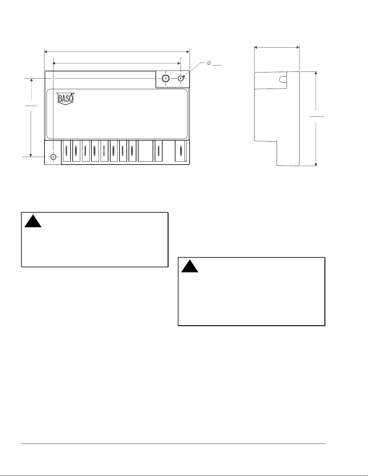
123.19
4.850
107.95
66.68
2.625
4.250
LED
Figure 1: Dimensions (mm/in.)
Wiring
!
WARNING: Risk of Explosion or Fire.
Locate all safety, limit, and operating controls in
series with the thermostat terminal (TH) on the
ignition control. Improper installation may cause gas
leaks, which can lead to an explosion or fire and
may result in severe personal injury or death.
Refer to Figure 2 and 3 for wiring diagrams. All wiring
should be in accordance with the National Electrical
Code (NEC) and all other local codes and regulations.
Check the voltage rating marked on the control and
make sure it is suited to the application. Use a Class 2
transformer capable of providing 24 VAC under
maximum load, including valves. A transformer having
excessive primary impedance due to poor coupling
affects the ignition potential.
38.10
1.500
3.96
.156
HOLE THRU
(2 HOLES)
LED
80.01
3.150
Spark Cable
The cable must be noise suppression (resistive) type
rated for at least 15kV and must not be in continuous
contact with a metal surface. If a separate flame sense
probe is used, the sense wire should be separated
from the high voltage wire by a minimum of
6.35 mm (1/4 in.).
!
WARNING: Risk of Electric Shock.
Before applying power to the control, connect the
high voltage cable to the spark transformer terminal
and spark electrode (pilot burner assembly). Verify
the ground wire is attached to the pilot burner and
the control ground terminal strip. Failure to follow
this procedure can cause electric shock and may
result in severe personal injury or death.
Controls with universal flame sense are supplied with
a jumper wire between SENSE and INTERN terminals
and is ready for internal (one rod) flame sense. With
the jumper in, flame is sensed through the high voltage
spark wire. For external (two rod) flame sense, the
jumper must be removed and discarded and the sense
electrode is wired to the SENSE terminal.
2 E Series EC/AGA Approved Intermittent Pilot Ignition Control Installation Instructions
Page 3

123
MAIN
GND
VALVE
PILOT
456
24V
GND
GND
BURNER
78 11
ALARM
SENSE
ALARM
9
RESET
10
INTERN
RESET*
THERMOSTAT
HIGH
TEMP
LIMIT
L1 (HOT)
L2 (NEU)
PILOT BURNER
COMBINATION
GAS VALVE
24 VAC
CLASS 2
TRANSFORMER
CHASSIS OR FRAME
GROUND
RESISTIVE NOISE SUPPRESSION WIRE
*RESET SWITCH ONLY FOR NON-VOLATILE LOCKOUT UNITS
Figure 2: Wiring for 1 Rod Flame Sense used for Internal Sense
SPARK
JUMPER WIRE
SUPPLIED WITH
THE CONTROL
REMOVE
JUMPER
11
SPARK
PILOT BURNER
2
1
GND
(VALVE)
MAIN
COMBINATION
GAS VALVE
*RESET SWITCH ONL Y FOR NON-VOLATILE LOCKOUT UNITS
3
PILOT
FLAME
SENSOR
45
GND
BURNER
6
7
ALARM
24V
GND
ALARM
THERMOSTAT
HIGH
TEMP
LIMIT
24 VAC
CLASS 2
TRANSFORMER
CHASSIS OR FRAME
GROUND
RESISTIVE NOISE SUPPRESSION WIRE
9
8
SENSE
RESET
RESET*
L1 (HOT)
L2 (NEU)
10
INTERN
Figure 3: Wiring for 2 Rod Flame Sense used for External Sense
E Series CE/AGA Approved Intermittent Pilot Ignition Control Installation Instructions 3
Page 4

Setup and Adjustments
Checkout
!
WARNING: Risk of Explosion or Fire. Verify
that there are no gas leaks by testing with appropriate
equipment. Never use a match or lighter to test for the
presence of gas. Failure to test properly can lead to an
explosion or fire and may result in severe personal injury
or death.
Make sure all components function properly by performing
the following test.
1. Before starting the appliance, perform a safety
inspection of piping, burners and venting. Check for
water leaks, etc. Check all wiring for proper
connections. Be sure the system is properly
grounded, including ground connection to the pilot
burner.
2. With the gas and thermostat off, turn on power to the
appliance.
3. Turn the thermostat to a high setting and verify that
the control goes through the operating sequence to a
shutoff condition.
Note: The burner does not light because the gas is
off.
4. Turn off the thermostat.
5. Turn on the gas and purge gas lines of all air.
6. Check for gas leaks on all pipe joints upstream of the
gas valve with a soap solution.
7. Turn the thermostat to the highest setting and verify
successful ignition and a normal run condition for at
least 5 minutes. If the appliance fails to run, see the
Troubleshooting section.
8. Check for gas leaks on all pipe joints downstream of
the gas valve with a soap solution.
9. Turn the thermostat down for at least 30 seconds
and then back up again. Verify successful ignition at
least five times.
10. Return the thermostat to a normal temperature
setting before leaving the installation.
!
WARNING:
The control module can not be serviced by user. If any
faults are detected, the control module must be
replaced. If control module has been opened or any
attempts to repair are done, the warranty is void.
Operation
Operating Mode Definitions
The following definitions describe the E Series operating
conditions.
• Waiting Time (Prepurge): The initial delay between
the start signal and the safety time to allow ventilation
of the combustion chamber and flue passages to
displace any unburned gas and/or products of
combustion.
• Safety Time (Trial for Ignition): The time between
energizing the pilot gas valve and de-energizing the
pilot gas valve if the flame signal is not detected.
• 100% Shutoff: Pilot gas did not ignite within the
safety time (trial-for ignition time) or the amount of
trials. The control de-energizes the spark circuit and
gas valve, and enters into lockout.
• Retrial: Failing an ignition attempt, the control enters
the inter-waiting time (retry) and then starts another
safety time (models with optional retrials).
• Running Position (Run): The main valve and pilot
valve remain energized and the spark is de-energized.
The appliance is in normal operation under the
supervision of the ignition control and its flame
detector device.
• Flame Loss Response (Inter-Purge): The loss of
proven flame. The main and pilot valves are turned off
(de-energized) and the control waits the recycle
(Inter-Purge) time before another spark sequence is
started. For controls without recycle (Inter-Purge) time
the main valve is turned off (de-energized) and pilot is
turned on (energized) and a spark sequence recurs
within 2.0 seconds.
• Volatile Lockout (Lockout): The safety shutdown of
the system where a startup sequence can only begin
after the thermostat contacts or main power is cycled
(off, then on) to reset lockout.
• Non-Volatile Lockout (Lockout): The safety
shutdown of the system where a startup sequence
can only begin after the operation of the external reset
switch to reset lockout.
• Recycle (Inter-Purge): If shutoff occurs, the control
delays for a specific recycle delay period before
beginning another trial for ignition (models with
recycle only).
• Inter-Waiting Time (Retry): Period between trials for
ignition when both the gas valve and spark is
deactivated to allow unburned gas to escape before
the next trial. Inter-Waiting (Retry) occurs between
unsuccessful trials on a multi-trial control.
• Alarm Output: The alarm output uses the normally
closed contact on the safety relay. It will turn on if
flame fails to light in the safety time or a fault is
detected in the control. The output will also be on for a
half second on power up until the safety relay turns
on.
4 E Series EC/AGA Approved Intermittent Pilot Ignition Control Installation Instructions
Page 5

Troubleshooting
If the system does not function properly, determine the
cause using the procedures in this section.
Before proceeding with troubleshooting the system, check
the following.
Preliminary Checks
Are you using resistive wire between the module
spark (11) and the pilot connection?
Are all mechanical and electrical connections tight?
Is the system wired and grounded correctly?
Is gas inlet pressure per manufacturer’s
specifications?
Is the thermostat calling for heat?
Is the system powered?
Table 1: LED Error Indications
LED Indications During Normal Operation
Orange once a second Waiting Time (Prepurge)
Red rapid flashing Safety Time Spark On (Trial for Ignition)
Steady green Running Position Flame On (Run)
Orange once every 5 seconds Inter-Waiting Time Between Cycles (Retry)
Orange once a second Flame Loss Waiting Time (Inter-Purge)
LED Error Indications
Red Green Error
1 0 Flame did not light in safety time (Trial for Ignition)
1 1 Flame sense circuit stuck on
1 2 Internal fault
1 3 Line frequency or micro clock error
2 1 Pilot valve fault
2 2 Pilot valve relay contact fault
2 3 Main relay fault
2 4 Main valve relay contact fault
Note: More than 2 red blinks indicate micro-memory or software fault.
E Series CE/AGA Approved Intermittent Pilot Ignition Control Installation Instructions 5
Page 6

Technical Specification
Product
Ignition Type
Ignition Source
High Voltage Cable
Maximum Length
Flame Sense Cable
Maximum Length
Flame Detection Means
Flame Detection Type
Minimum Flame Current
Flame Failure Response
Time
Maximum Spark Gap
Power Requirements
Contact Rating
Wiring Connections
Burner Rating
Ambient Operating and
Storage Temperature
Humidity
Type of Gas
Packaging
Bulk Pack Quantity
Pack Weight
Agency Listing
Specifications Standards
The performance specifications are nominal and conform to acceptable industry standards. All agency
certification of BASO products is performed under dry and controlled indoor environmental conditions. Use of
BASO products beyond these conditions is not recommended and may void the warranty. If the product is
exposed to water (dripping, spraying, rain, etc.) or other harsh environments, it must be protected. The original
equipment manufacturer or end user is responsible for the correct application of BASO products. For questionable
applications, please consult BASO Gas Products LLC. BASO Gas Products LLC shall not be liable for damages
or product malfunctions resulting from misapplication or misuse of its products
EC/AGA Universal Intermittent Pilot Ignition Control
Indirect
High voltage spark, capacitive discharge
1,220 mm (48 in.) (Resistive wire recommended, rated for at least 15Kv.)
1,220 mm (48 in.)
Flame Rectification
Local or Remote
0.15 microamperes
2 seconds maximum
5.1 mm (0.2 in.)
Control:
Operation Current:
Main Valve:
Pilot Valve:
Alarm Output
6.35 mm (1/4 in.) male spade
117 kW (400,000 Btu/hr)
-40 to 77°C (-40 to 176°F)
95% RH noncondensing
Natural, Liquefied Petroleum (LP), Manufactured, Mixed or LP Gas-Air Mixture
Bulk pack supplied to original equipment manufacturer (individual pack [-1AAC] or overpack
25
Bulk pack (-1AAD) 6.36 kg (14 lb)
Individual pack (-1AAC) .454 kg (1 lb.)
EC Certification Number EC-86/10/147
AGA Certification Number 7811
ANSI Standard Z21.20
CAN/CSA-C22.2 No. 199
24 VAC (+/- 20%), 50/60 Hz
0.2 A nominal + valves
2 A maximum
2 A maximum
1 A maximum
1007 South 12th Street
PO Box 170
Watertown, WI 53094 www.baso.com
1-877-227-6527 (1-877-BASOGAS Published in U.S.A.
6 E Series EC/AGA Approved Intermittent Pilot Ignition Control Installation Instructions
 Loading...