

Page 1

Installation Instructions
Issue Date November 3, 2011
BGQ15HAA-1 Retrofit Spark Ignition System
Installation
Parts Included
The retrofit package includes:
• (1) BGD278JBE-20BCGD gas valve
• (1) BG1600M10EK-1AA spark ignition control
• (1) Rajah adapter
!
CAUTION: Risk of Electric Shock.
Disconnect power supply before making electrical
connections to avoid electric shock.
• (4) 1/4 inch female quick connects
• (1) Sensing probe cable
• (1) 1/8 inch NPT to 1/4 cc elbow fitting
• (1) Reducer bushing (3/4” to 1/2” NPT)
• (1) Compression fitting (1/4” tube)
• (1) Y75RJ-1 retrofit sensor probe kit
• (1) Sensor probe extension and (1) bushing
• (2) Spacers and (1) cone shaped nut
• retrofit package installation diagram and a
pressure sensitive lighting Caution sticker
Special Tools Needed
The following tools may be needed.
• manometer
• DC microammeter and AC voltmeter
• assorted pipe nipples and fittings
• On/Off toggle switch with wire leads and clips
Remove the Existing Gas Valve
IMPORTANT: Only qualified personnel should
install or service BASO Gas Products. These
instructions are a guide for such personnel. Carefully
follow all instructions in this document and all
instructions for the appliance.
IMPORTANT: Make all gas installations in
accordance with applicable local, national, and
regional regulations.
!
WARNING: Risk of Explosion or Fire.
Shut off the gas supply at the main manual shutoff
valve before installing or servicing the
BGQ15HAA-1. Failure to shut off the gas supply can
result in the release of gas during installation or
servicing, which can lead to an explosion or fire, and
may result in severe personal injury or death.
!
WARNING: Risk of Explosion, Fire, or
Electric Shock. Label all wires before they are
disconnected when replacing or servicing the
BGQ15HAA-1. Wiring errors can cause improper or
dangerous operation and may result in an explosion,
fire, or electric shock leading to severe personal
injury or death.
All installations must comply with local codes or, in the
absence of local codes, with the National Fuel Gas
Code, ANSI Z223.1, and the National Electrical Code
(NEC), ANSI/NFPA 70.
To remove the existing gas valve.
1. Set the thermostat at its lowest setting.
2. Turn off the power to the appliance.
3. Turn off the gas at the main manual shutoff valve.
4. Remove the thermocouple from the gas valve.
5. Disconnect the pilot tubing from the gas valve
Disconnect all wires from the existing gas valve.
6. Carefully remove the old gas valve from the
manifold.
© 2011 BASO Gas Products 1
Part No. BASO-INS-BGQ15, Rev. — www.baso.com
Page 2
Install the Sensing Probe and Cable
To install the sensing probe and cable:
1. Remove the thermocouple from the existing pilot
burner. The pilot burner should be left on its
mounting bracket if you can conveniently reach it.
If not, it may be necessary to partially pull out the
manifold for easy access. In some extreme
cases, it may be necessary to remove the pilot. If
it becomes necessary to replace the pilot burner,
it must be replaced with an identical model and
positioned using the original mounting.
2. Place the threaded end of the sensing probe
assembly into the thermocouple hole in the pilot.
3. Check the position of the spark gap. The spark
gap should be 0.1 in. (2.5 mm) nominal.
Note: Position the spark gap in the pilot gas
stream. Raise or lower the spark gap by adding
or removing the spacers provided between the
pilot and sensing probe assembly.
4. Screw the cone shaped nut onto the probe. The
small end fits into the threaded thermocouple
hole to center the sensing probe and secure it in
place.
5. Depending upon the appliance, the flame sensing
probe may be mounted in a number of positions.
Select the position providing the most clearance
from metal surfaces and the main burner flame.
2. When installing the ignition system on the
manifold, ensure that the gas flows through the
valve body in the direction indicated by the arrow
on the valve body. If the ignition system is
installed with the gas flow in the opposite
direction of the arrow, leakage can occur.
IMPORTANT: Do not use a wrench on any
surface other than the casting flats provided at the
inlet and outlet ends of the valve body. The
BGQ15HAA-1 may be damaged in the mounting
process if a wrench is used on any other surface.
Using a wrench incorrectly may void the warranty.
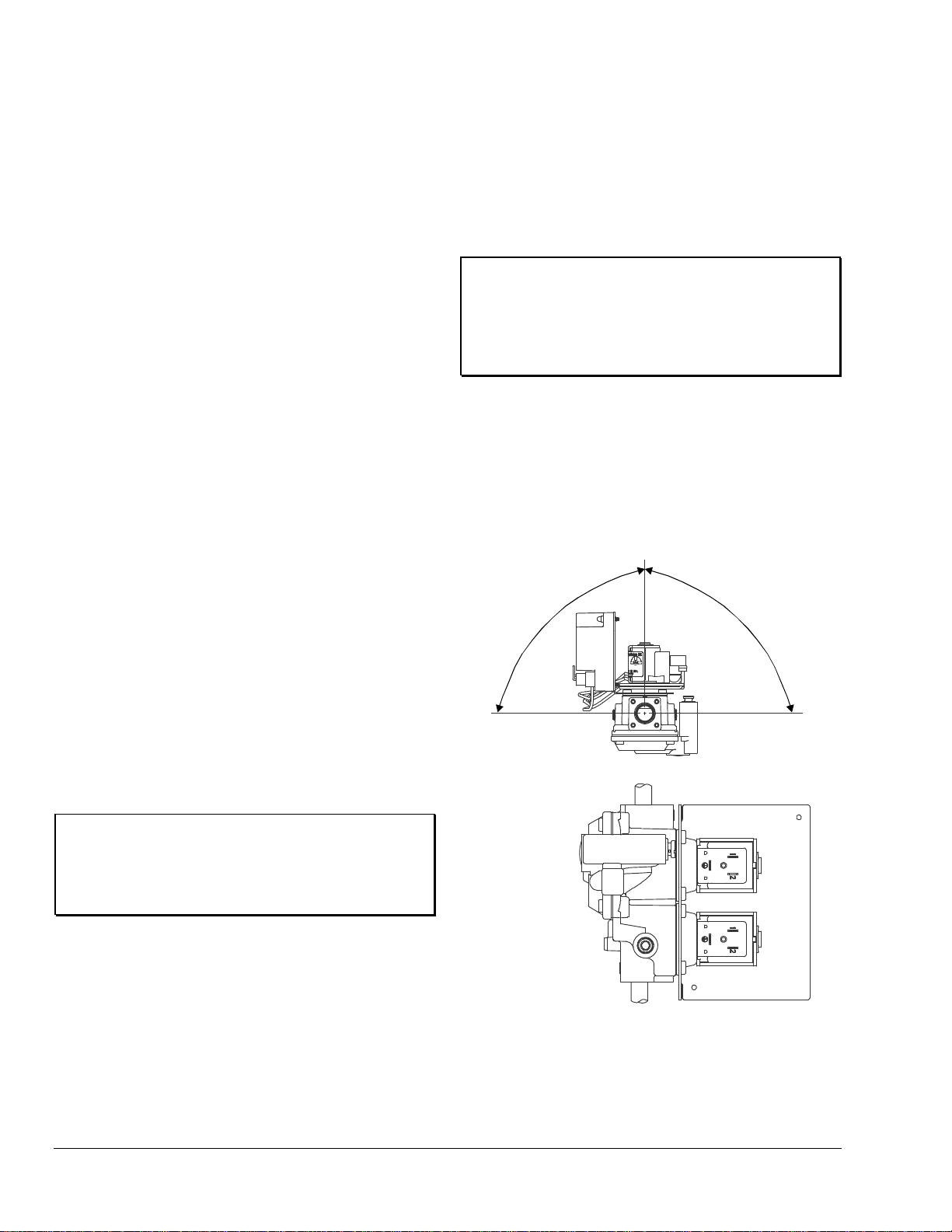
3. Mount the BGQ15HAA-1 ignition system on a
horizontal manifold with the ignition control
pointed up (vertical) or in a position not
exceeding 90° from vertical manifold in any
position around its axis (Figure 1).
Note: Additional piping may be required if
face-to-face dimensions are not the same.
90° Maximum
from Vertic al
90° Maximum
from Vertic al
6. Install the sensing probe cable onto the spade
connector of the sensor.
7. If the pilot burner was removed, reinstall the pilot
on its bracket in the furnace using the original
mounting.
Mounting
IMPORTANT: Verify that the valve is installed
only in applications where the specified maximum
ambient (surface) temperature and maximum
operating pressures do not exceed the limits in the
Technical Specifications section.
To install the BGQ15HAA-1 ignition system:
1. Compare the voltage on the valve with the power
source voltage to ensure the correct unit is being
installed. For valves with 25 volt coils, use an
NEC, Class 2 transformer.
Note: The transformer must be mounted to a
grounded metal enclosure.
Vertical mo unting may
be 360º ar ound its axis
with the gas flow either
up or dow n, but always in
the direction of the arrow.
Figure 1: BGQ15HAA-1 Mounting Positions
2 BGQ15HAA-1 Retrofit Spark Ignition System Installation Instructions
Page 3

4. Mount the ignition system to the pipework. Use
an approved pipe joint sealing compound on the
male threads before assembling. Remove excess
compound after mounting the ignition system to
the pipework. Threads of the pipe and nipples
must be smooth and free of tears and burrs.
Steam clean all piping to remove foreign
substances such as cutting oil or thread chips. A
sediment trap must be installed in accordance
with the National Fuel Gas Code (ANS Z223.1).
See Figure 2.
5. Connect the pilot tubing to the valve assembly
with the 1/8 in. NPT to 1/4 in. cc elbow fitting, if
needed
!
WARNING: Risk of Explosion or Fire.
Verify that there are no gas leaks by testing with
appropriate equipment. Never use a match or lighter
to test for the presence of gas. Failure to test
properly can lead to an explosion or fire and may
result in severe personal injury or death.
6. Check for leakage.
a. Shut off the gas at the main manual shutoff
valve and open the pressure connection
between the manual shutoff valve and the
BGQ15HAA-1 valve.
b. Connect air tubing with a maximum pressure
of 1-1/2 times the valve’s maximum operating
pressure (as indicated on the valve) to the
opened pressure connection.
c. Paint all valve body connections with a rich
soap and water solution.
If bubbles occur, this indicates a leak. To stop
a leak, tighten joints and connections. Replace
the part if the leak cannot be stopped.
If bubbles do not occur, remove the air tubing
and close the pressure connection.
7. Perform the Checkout section before leaving the
installation.
Gas Flow
Manual Shutoff
Sediment
Trap
Valve
"X"
3 in. (76.2 mm)
Minimum
BGQ15 Ignition
System
“X” in dicate s po ssible
locations f or ot her contr ol s.
"X”
Burner
Figure 2: Typical Installation of a BGQ15HAA-1
BGQ15HAA-1 Retrofit Spark Ignition System Installation Instructions 3
Page 4

Wiring
!
WARNING: Risk of Explosion or Fire.
Locate all safety, limit, and operating controls in
series with the thermostat terminal (TH) on the
ignition control. Improper installation may cause gas
leaks, which can lead to an explosion or fire and
may result in severe personal injury or death.
Refer to Figure 3 or Figure 4 for wiring diagrams. All
wiring should be in accordance with the National
Electrical Code (NEC) and all other local codes and
regulations.
Check the voltage rating marked on the control and
make sure it is suited to the application. Use a Class 2
transformer capable of providing 24 VAC under
maximum load, including valves. A transformer having
excessive primary impedance due to poor coupling
affects the ignition potential.
The high-voltage spark transformer cable is noise
suppression (resistive) type rated for at least 15 kV
and must not be in continuous contact with a metal
surface. Use standoff insulators. Ensure that the flame
sensor wire and high voltage spark transformer cable
are separated from one another by a minimum of
1/4 in. (6.35 mm) and are not wrapped around any
pipe, other wiring, or accessories.
Note: A shorting plug that jumpers pins 2 and 3 of the
damper connector is supplied with the control. The
shorting plug must be used if a vent damper is not
used. When a vent damper has been connected and
power turned on, an internal fuse in the control will
blow and the control will only operate with a vent
damper connected. Now you cannot disconnect the
vent damper plug and put back the shorting plug. The
ignition control will not work.
!
WARNING: Risk of Electric Shock.
Before applying power to the control, connect the
high voltage cable to the spark transformer terminal
and spark electrode (pilot burner assembly). Verify
the ground wire is attached to the pilot burner and
the control ground terminal strip. Failure to follow
this procedure can cause electric shock and may
result in severe personal injury or death.
The BGQ15HAA-1 replaces existing intermittent pilot
ignition controls with the following specifications:
• flame detection using flame rectification
technology (ability of a flame to conduct and
rectify current)
• trial for ignition 1 trial
• dual rod (remote sense) flame sensing
• no retry
• infinite trial time
• prepurge period of none
• inter-purge period of 5 seconds
• main burner 400,000 Btu/hr maximum
• pilot burners with flow rates of 1,500 Btu/hr or
less
• with or without automatic vent damper
• must be used with redundant gas valves and
not subjected to temperatures below
-40˚F (-40˚C) or above 170˚F (77˚C)
4 BGQ15HAA-1 Retrofit Spark Ignition System Installation Instructions
Page 5

MV/PV
(COM)
2
PV
3
MV
1
GND
456
24V
GND
BURNER
Use jumper
plug s u pp li ed
with control.
SENSE
TH
7
8
SPARK
INTERNAL
9
10
Thermostat
5
3
High
Temp
Limit
Pilot
Burner/Ignitor
1
Power Supply. Provides disconnect means and overload protection as required.
Maximum cable length 48 in ches (1,220 mm). (Resisti ve wire reco m mended.)
2
3
Alternate location for limit controller.
4
Controls in 24V circuit must not be in ground leg to transformer.
5
Maximum cable length 48 inches (1,22 0 mm) .
Sensor rod must be 3/8” (9.53 mm) to 1/2” (12.7 mm) of the sensor tip should
6
be in the flame for proper sensing signal.
6
Flame
Sensor
4
24VAC
Class 2
Transformer
Chassis or Frame
Ground
1
L1 (Hot)
L2 (Neu)
2
Figure 3: Wiring for 2 Rod Flame Sense with Vent Damper Jumper Plug
Discard jumper
plug supplied
MV/PV
MV
(COM)
2
1
PV
3
GND
45
GND
BURNER
with the control.
24V TH
67
SENSE
89
INTERNAL
DAMPER
PLUG
SPARK
10
Wiring
Harness
Thermostat
24VAC
Class 2
Transformer
Chassis or Frame
3
4
Ground
Combination
Gas Valve
Pilot
Burner/Ignitor
1
Power Supply. Provides disconnect means and overload protection as required.
Maximum cable length 48 in ches (1, 220 mm). (Resisti ve wire rec om m ended.)
2
3
Alternate location for limit controller.
4
Controls in 24V circuit must not be in ground leg to transformer.
Maximum cable length 48 inches (1,220 mm).
5
Sensor rod must be 3/8” (9.53 mm) to 1/2” (12.7 mm) of the sensor tip should
6
be in the fla me f or pr oper sensin g s i gnal.
6
Flame
Sensor
High
Temp
Limit
5
L1 (Hot)
L2 (Neu)
Vent
1
Damper
2
Figure 4: Wiring for 2 Rod Flame Sense with Vent Damper
BGQ15HAA-1 Retrofit Spark Ignition System Installation Instructions 5
Note:
If a damper i s not used
(see Figure 3), use
pin 2-3 jumper plug
supplied with the control
and omit 24V connection.
Page 6

/
j
Setup and Adjustments
Electrical and Mechanical Checkout Procedure
After the BGQ15HAA-1 installation is complete, perform
the following procedures to ensure the installation is
correct. While performing the following procedure, keep
the high voltage cable and the sensing probe cable away
from hot surfaces.
1. Measure the output current in the probe circuit using
a DC microammeter. Connect the microammeter
leads between the sensing probe cable and Terminal
8 on the ignition control. Connect the positive lead to
Terminal 8 and the negative lead to the sensing
probe cable (Figure 5).
MV
1
MV
(COM) P V
2
PV
3
456
GND
BURNER
GND 24V SENSE
TH
7
8
910
INTERNAL
SPARK
Use
plugsupplied
with contr ol.
umper
Flame
Sensor
Digital Multi mete r
Positive
Lead
Flame
Sensor
Cable
Note: Once the pilot flame is lit, the microammeter
shows a reading from the flame sensing probe. The
current reading should be at least 0.15 microampere.
If the reading is less than 0.15 microampere, turn off
the electrical power and adjust the pilot assembly by
adding spacers between the pilot bracket and the
sensing probe assembly. No more than 1/2 in. of the
flame sensor tip should be in the pilot flame. If this
does not correct the current reading, it may be
necessary to increase the pilot burner orifice size.
Recheck until the reading is satisfactory.
6. Flip the toggle switch to the Off or open position.
7. Reconnect the main valve lead to Terminal 1 on the
ignition control.
8. Flip the toggle switch to the On or closed position.
The pilot should light and immediately thereafter, the
main burner should light.
9. Check the outlet pressure reading by removing the
pressure tap plug and connecting a manometer.
Compare it with the furnace or boiler specifications. It
may be necessary to adjust the pressure regulator to
the rating indicated (see the Regulator Adjustment
section).
Negative
Lead
Figure 5: Wiring Diagram for Flame Sensing Current
Measurement
2. Remove the main valve lead from Terminal 1 on the
ignition control. Attach the on/off toggle switch
between the ungrounded post of the transformer and
Terminal 7 on the ignition control. The toggle switch
serves as the thermostat for testing procedures.
Make sure the thermostat contacts are open.
3. Open the main manual shutoff valve to turn on the
gas supply.
4. Restore power to the furnace or boiler and flip the
toggle switch to the On or closed position. The pilot
valve opens and a spark jumps the spark gap at the
pilot.
5. Test for leaks at the pilot tubing connections with a
soap solution. In a few seconds, the spark lights the
pilot after the air is bled from the pilot gas line.
Turndown Test Procedure
With the toggle switch still connected, perform the
following turndown test to assure main burner ignition
under conditions that permits the main valve to open.
1. Slowly close the manual shutoff valve until the pilot
flame is just sufficient to maintain operation of the
main burner.
2. Cycle the main burner off and on with the toggle
switch. Perform this test with the furnace or boiler
burner cold and hot.
3. If the furnace or boiler cycles without igniting the
main burner in four seconds, ensure the pilot is
properly located and correct for the application.
4. Completely open the main manual shutoff valve.
5. If unstable burner lighting occurs, causing the ignition
control to chatter on and off during startup, install the
flame rectification extension as follows.
a. Place the sensor probe extension and bushing
onto the flame sensing probe.
b. Position the extension over the main burner so it
extends into the flame.
c. Secure the extension in place by tightening the
extension probe into the bushing.
Note: The sensor probe extension detects the main
burner flame and the BG1600M ignition control
allows continued operation until a stabilized pilot is
maintained.
6 BGQ15HAA-1 Retrofit Spark Ignition System Installation Instructions
Page 7

6. Ensure the thermostat contacts are open and remove
the toggle switch.
7. Remove the microammeter and reconnect the sensor
probe lead to Terminal 8 on the ignition control.
8. Shut off the gas supply at the main manual shutoff
valve, disconnect the manometer, and replace the
pressure tap plug.
Note: The thermostat heat anticipator setting
should be set for 0.4 ampere (current draw of the
BGQ15HAA-1 gas valve). When using an automatic
vent damper, add the current draw of the vent
damper to the 0.4 ampere of the gas valve. The
transformer should be checked to make sure it has
sufficient capacity to operate the additional load.
9. Reopen the main manual shutoff valve.
10. Perform the Checkout section before leaving the
installation.
Thermostat Heat Anticipator Settings
The anticipator setting is normally equal to the ignition
system current, plus that of the pilot and main valve.
Due to variations in appliance wiring and valves, it is
advisable to measure the actual current draw of the
heating system at the thermostat location. Measuring this
current can be accomplished by opening the thermostat
contacts (lowering the setpoint) and installing an AC
ammeter across the terminals, or by using a clamp-on
ammeter with a 10-turn multiplier attached to the terminals
(Figure 6).
To
Heating
System
To
Heating
System
R
W
R
AC Ammeter Low
Scale Setting
W
Ten Turns
Clamp- on Amme ter
(Divide reading by ten.)
Figure 6: Measuring the Thermostat Current
Regulator Adjustment
!
WARNING: Risk of Explosion or Fire. Do not
adjust the minimum flow rate of the valve below the
minimum safe working rate of the appliance. This may
cause gas leaks, which can lead to an explosion or fire,
and may result in severe personal injury or death.
!
WARNING: Risk of Personal Injury. Do not
take a current draw measurement unless the appliance
is in the run condition. Measuring the current with an
ammeter will energize the system. This may cause the
appliance to proceed to the run condition unexpectedly,
and may result in severe personal injury or death.
BGQ15HAA-1 Retrofit Spark Ignition System Installation Instructions 7
IMPORTANT: Refer to and follow any specific
instructions issued by the appliance manufacturer with
regards to servicing their equipment.
The pressure regulator is adjustable and has been factory
set at 3.5 in. W.C. (8.75 mbar). If a different setting is
desired, follow these instructions.
1. Shut off all gas to the appliance.
2. Turn the thermostat to the lowest setting or Off
position.
3. Remove the pressure tap plug at the valve outlet or
in the manifold pipe downstream of the valve.
4. Install a manometer or pressure gauge suitable for
measuring the desired orifice pressure.
Page 8

5. Remove the seal screw at the end of the regulator
stack.
6. Turn the gas on and place the thermostat at the
highest setting to cycle the ignition system.
7. Allow the system to stabilize. Adjust the screw in the
regulator stack to the desired reading on the
manometer. (Turn clockwise to increase the outlet
pressure and counterclockwise to reduce the outlet
pressure.)
8. Reinstall the seal screw, which incorporates the
proper size hole for venting to the atmosphere. (It
may be necessary to cycle the valve several times to
verify the desired outlet pressure.)
9. Turn off the gas supply and place the thermostat at
the lowest setting.
10. Remove the manometer and reinstall the pressure
tap plug.
11. Turn the gas on and check for leaks at the pressure
tap plug with a soap solution.
12. Set the thermostat to the desired setting before
leaving the site.
3. Turn the thermostat to a high setting and verify that
the control goes through the operating sequence to a
shutoff condition.
Note: The burner does not light because the gas is
off.
4. Turn off the thermostat.
5. Turn on the gas and purge gas lines of all air.
6. Check for gas leaks on all pipe joints upstream of the
gas valve with a soap solution.
7. Turn the thermostat to the highest setting and verify
successful ignition and a normal run condition for at
least 5 minutes. If the appliance fails to run, see the
Troubleshooting section.
8. Check for gas leaks on all pipe joints downstream of
the gas valve with a soap solution.
9. Turn the thermostat down for at least 30 seconds
and then back up again. Verify successful ignition at
least five times.
10. Return the thermostat to a normal temperature
setting before leaving the installation.
Checkout
!
WARNING: Risk of Explosion or Fire. Follow
this or an equivalent checkout procedure after
installation. Before leaving the installation, verify that the
BGQ15HAA-1 functions properly and that the system
has no gas leaks. Gas leaks can lead to an explosion or
fire, and may result in severe personal injury or death.
!
WARNING: Risk of Explosion or Fire. Verify
that there are no gas leaks by testing with appropriate
equipment. Never use a match or lighter to test for the
presence of gas. Failure to test properly can lead to an
explosion or fire and may result in severe personal injury
or death.
Make sure all components function properly by performing
the following test.
1. Before starting the appliance, perform a safety
inspection of piping, burners and venting. Check for
water leaks, etc. Check all wiring for proper
connections. Be sure the system is properly
grounded, including ground connection to the pilot
burner.
!
WARNING:
The control module can not be serviced by user. If any
faults are detected, the control module must be
replaced. If control module has been opened or any
attempts to repair are done, the warranty is void.
Operation
Operating Mode Definitions
The following definitions describe the BG1600M operating
conditions.
• Prepurge: Initial time delay between thermostat
contact closure and activation of the spark circuit and
pilot valve.
• Trial for Ignition: Total time the pilot valve is
energized and spark/sense sequence is activated in
an attempt to light the pilot. The control attempts to
prove flame within the trial-for-ignition time.
• 100% Shutoff: If the control does not prove the
presence of pilot burner flame within the trial for
ignition, the spark circuit and pilot valve are
de-energized.
• Recycle: If 100% shutoff occurs, the control delays
for a specific recycle delay period before beginning
another trial for ignition (models with recycle only).
2. With the gas and thermostat off, turn on power to the
appliance.
8 BGQ15HAA-1 Retrofit Spark Ignition System Installation Instructions
Page 9

• Run: Main valve is energized and spark turns off after
pilot flame is proven. The main valve remains
energized until the thermostat is satisfied.
• Flameout: Loss of proven flame. Should a flameout
occur, the main valve de-energizes and spark recurs
within 2.0 seconds.
• Lockout: An internal or external fault has caused the
control to de-energize the spark circuit and valve
relays. The thermostat contacts must be opened for
30 seconds and then closed to begin another trial for
ignition.
• Inter-Purge: Period between trials for ignition when
both the gas valve and spark are de-activated to allow
unburned gas to escape before the next trial.
Sequence of Operation
The heating cycle start when a call for heat from the
thermostat supplies 24VAC to the TH terminal. The
automatic vent damper (if used) is energized and when
fully open, turns on the power to the ignition control. After
a 1 second maximum diagnostic period, the spark will
start and the pilot valve will turn on, starting with the trial
for ignition period.
During the trial for ignition period, the control sparks for 4
seconds while rapidly flashing LED. It then turns off the
spark and LED for 1 second while checking pilot flame
sense. This cycle will repeat until pilot flame is detected or
trial time is over.
When pilot flame is detected, the spark will stop, main
valve will turn on and the LED will stay on continuously.
The control will remain in this state until the pilot flame is
lost or the call for heat ends. If pilot flame is lost, LED,
main and pilot valves are turned off for 0.5 seconds and a
new trial for ignition sequence will star t.
Troubleshooting
If the system does not function properly, determine the
cause using the procedures in this section.
Before proceeding with troubleshooting the system, check
the following.
Preliminary Checks
Are you using resistive wire between the module
spark (10) and the pilot connection?
Are all mechanical and electrical connections tight?
Is the system wired and ground correctly?
Is gas inlet pressure per manufacturer’s
specifications?
Is the system powered?
Is the thermostat calling for heat?
!
WARNING: Risk of Personal Injury.
Do not place face, hands, or other parts of the body in
or near the burner area when the LED is flashing
(recycle mode). When the LED is flashing, the control
may at any time (while in the recycle mode) re-energize
the burner control system and ignite the burner which
may result in electric shock from contact with the
electrode or severe burn injury from firing of the burner.
If pilot flame is not detected during the trial for ignition
period, the pilot valve will be shut off. Lockout will occur if
your model has no retry. Otherwise, after 5 minutes or 60
minutes (for recycle units only) the control will delay for
the specific recycle delay period before beginning another
trial for ignition.
Table 1: LED Indications During Normal Operation
Flash Code Flash Code Indication
Steady On Flame detected, main burner on
.1 Second On
.1 Second Off
1.0 Second On
Trial time spark on trying to light
pilot burner
2 minute recycle delay time
4.0 Second Off
BGQ15HAA-1 Retrofit Spark Ignition System Installation Instructions 9
Page 10

LED Error Indications
If the control module’s internal diagnostics detect a fault it
will go into lockout. Spark and both valves will be turned
off. The LED will flash an error code .25 seconds on and
.25 seconds off for each count of the error code with
1 second off between codes. The control will remain in
this condition until power is removed by turning off the call
for heat. A flashing LED error code indicates either a
problem with wiring, or a component not working, or the
control module is faulty. Try to cycle the control again. If
the error repeats then see Table 2 for troubleshooting.
Table 2: LED Error Indications
Flash
Code
Flash Code
Description
Troubleshooting Guide
1. Check Controller for a Molex connection;
1.1. Controller w/MOLEX connector and the Vent Damper jumper plug installed, check for
No
LED“
ON”
No Power
24 volts on terminal 7 (TH) and terminal 5 (GND). If using a Vent Damper, make sure it is
connected and the damper is working, check for 24 volts on terminal 6 (24V) and
terminal 7 (TH) to terminal 5 (GND).
1.2. Controller w/o MOLEX connector, check for 24 volts on terminal 6 (24V) and terminal
5 (GND).
2. Check for 24 volts on the secondary coil of the incomi ng transformer.
1. Check if the gas is turned “ON”.
2. Check Controller for a Molex connection;
2.1. Controller w/MOLEX connector and the Vent Damper jumper plug installed, check for
24 volts on terminal 7 (TH) and terminal 5 (GND). If using a Vent Damper, make sure it is
connected and the damper is working, check for 24 volts on terminal 6 (24V) and
1
No flame in
trial time
terminal 7 (TH) to terminal 5 (GND).
2.2. Controller w/o MOLEX connector, check for 24 volts on terminal 6 (24V) and terminal
5 (GND).
3. If no spark, check spark wire and connection to terminal 10 (SPARK) and spark ground
to terminal 4 (GND BURNER).
4. Check if PV is wired to terminal 3 (PV) and common is wired to terminal 2 (MV/PV COM).
5. Check for 24 volts at the PV coil.
1. Check Flame Sensor tip is in the flame. For proper sensing the rod tip must be 3/8”
(10mm) to 1/2” (13 mm) in the flame.
2
Flame
sense circuit
error
2. Check Flame Sensor Circuits;
2.1 For 1 Rod Flame Sense circuit, check Spark/Flame S ensor is wired to terminal
10 (SPARK) and terminal 4 (GND BURNER).
2.2 For 2 Rod Flame Sense circuit, check Flame Sensor is wired to terminal 8 (SENSE) and
terminal 4 (GND BURNER).
3
4
5
6 to 9
PV
(Pilot Valve)
circuit error
MV
(Main Valve)
circuit error
Internal
Control error
Internal
Control error
1. Check for 24 volts on terminal 3 (PV) and terminal 2 (MV/PV COM).
2. Check for 24 volts at the PV coil.
3. Check if PV is wired to terminal 3 (PV) and common is wired to terminal 2 (MV/PV COM).
1. Check for 24 volts on terminal 1 (MV) and terminal 2 (MV/PV COM).
2. Check for 24 volts at the MV coil.
3. Check MV is wired to terminal 1 (MV) and common is wired to terminal 2 (MV/PV COM).
1. Review all ground connections.
2. Check if using fiber core resistive wire for Spark Wire.
1. Software error – Restart control module.
NOTE: If Troubleshooting Guide has been used, and the Control Module is flashing an ERROR CODE, then the
Control Module may be faulty. Replace the Control Module.
10 BGQ15HAA-1 Retrofit Spark Ignition System Installation Instructions
Page 11

Idle State
Call for heat
from the thermostat
If damper connected
wait for it to open
POWER TO CONTROL
One second for
diagnos t ic routine s
Note:
If the thermostat opens,
the control will turn off valves
and returns to the idle state.
Wait 0.1 se cond
checking memory and
relay driver circuits
Flame
on?
OK
No
Yes
FLAME ON
LOOP
If pre-pu r ge wait
flashing LED once a
second unt il ove r
Turn on spark and
pilot gas valve
start trial timer
Spark on 4 seconds
blinking LED rapidly
spark of f 1 second
Flame
on?
No
TRIAL
TIME
LOOP
Trial
No
TIME
Tur n pilot gas
over?
Yes
valve off
Retry
option?
Yes
TRIAL
OVER
Yes
Wait 0.5 se cond
Flame
No
on?
Yes
Tur n on m a in
gas valve and LED
reset try count
0.7 second?
RE-IGNITION
Yes
Turn main gas
valve off, start s park
and t rial timer
Turn pil ot and main
gas valves off
wait 0.7 second
inter - purge bl i nk ing
LED once a second
RELIGHT
Flame off
Yes
Re-Ignition
No
RECYCLE
No
FLAME LOST
Lock out on t imeout or fa ult detected,
Note:
turn off re lays and spark loop bl inking
error code unti l power off.
Error Codes
No flame in trial time.
Flame se nse stuck on .
Pilot relay driver fault.
Main relay driver fault.
Processor errors.
1 Blink
2 Blinks
3 Blinks
4 Blinks
5 to 9 Blinks
Trie s over
Wait 5 or 60 minutes,
blink LED ev er y 15 seconds
Lockout
RESTART
Figure 7: Sequence of Operation
BGQ15HAA-1 Retrofit Spark Ignition System Installation Instructions 11
Page 12

Turn on power
and gas.
Close thermostat
contacts.
Module LED
did not light and
no spark?
No
Module LED
blinks slowly?
No
Module LED
blinks rapidly but
no spark?
No
Pilot flame
does not
light?
No
Yes
Yes
Yes
Yes
Diagnostic error
see next page .
Replace module.
Spark wire
and electrode
OK?
No
Replace spark wire
or electrode.
24V between
PV and GND
terminals?
No
Replace
module.
Yes
Replace
module.
Yes
Gas at pilot
Adjust or replace spark
electro de and /or pilot
24V between
TH and GND
Connect pin 2-3
shor ting plug to
burner?
Yes
burner.
terminals?
Yes
Damper
used?
No
Shorting
plug in?
No
damper.
No
No
Check transformer,
thermostat and wiring.
Repair or replace as needed.
Yes
24V between
damper pin 2 & 4?
Yes
Yes
Check orfice and tubing are clear.
Replace
module.
Check shutoff valves are on.
Check wiring to pilot valve.
If all OK replace pilot valve.
No
Check and repair
damper, and/or
damper wiri ng.
Pilot lights
but keeps
sparking?
No
Pilot is lit
continued
on next page
Pilot flame in contact
with spark or sense
electrode?
Yes
Two rod
flame sense?
Yes
Check wiring electrode
to SENSE terminal.
If OK replace module.
NoYes
No
Check burner orifice.
Adjust pilot flame size or
electro de position.
Replace
module.
Figure 8: Troubleshooting Flow Chart (1 of 2)
12 BGQ15HAA-1 Retrofit Spark Ignition System Installation Instructions
Page 13

Continued
from p revious page
Pilot is lit
Main burner
failed to turn
on?
No
After main is
lit, do valves turn off
and star t new
cycle?
No
Control is
operating
normally.
Yes
Yes
Yes
24V between
MV and MV/PV
terminals?
No
Replace
module.
Pilot flame in
contact with spark or
sense el ectrode?
Yes
Two rod
flame sense ?
Yes
Yes
No
No
Gas at main
burner?
Adjust pilot flame size
and posit ion, or replace
pilot burn er or m ain burner.
Adjust pilot flame size or
Replace
module.
No
Yes
electrode position.
Check that shutoff valves are on.
Check wiring to main valve.
Check tubing is clear.
If all OK replace main valve.
Check wiring electrode
to SENSE terminal.
If OK replace module.
Figure 9: Troubleshooting Flow Chart (2 of 2)
BGQ15HAA-1 Retrofit Spark Ignition System Installation Instructions 13
Page 14

Maintenance Requirements in Severe
Environments
Regular preventive maintenance is important in any
application, but especially so in commercial cooking,
agricultural, and industrial applications because:
• In many such applications, particularly
commercial cooking, the equipment operates
100,000 to 200,000 cycles per year. Such heavy
cycling can wear out the gas control in one to
two years. A normal forced air furnace, for which
the controls were originally intended, typically
operates less than 20,000 cycles per year.
• Exposure to water, dirt, chemicals, and heat can
damage the ignition control module or the gas
control and shut down the control system. A
NEMA 4 enclosure can reduce exposure to
environmental contaminants.
!
WARNING: Risk of Explosion or Fire. Do
not attempt to take the ignition control module apart
or to clean it. Improper reassembly and cleaning
may cause unreliable operation, which can lead to
an explosion or fire, and may result in severe injury,
property damage or death.
Maintenance frequency must be determined
individually for each application. Some considerations
are:
• Cycling Frequency – Appliances that may cycle
more than 20,000 times annually should be
checked monthly.
• Intermittent Use – Appliances that are used
seasonally should be checked before shutdown
and again before the next use.
• Consequence of Unexpected Shutdown –
Where the cost of an unexpected shutdown
would be high, the system should be checked
more often.
Repairs and Replacement
!
CAUTION: Risk of Electric Shock.
Disconnect power supply before making electrical
connections to avoid electric shock.
!
WARNING: Risk of Explosion or Fire.
Shut off the gas supply at the main manual shutoff
valve before installing or servicing the control.
Failure to shut off the gas supply can result in the
release of gas during installation or servicing, which
can lead to an explosion or fire, and may result in
severe injury or death.
!
WARNING: Risk of Explosion, Fire, or
Electric Shock. Label all wires before they are
disconnected when replacing or servicing the
BGQ15HAA-1. Wiring errors can cause improper or
dangerous operation and may result in an explosion,
fire, or electric shock leading to severe personal
injury or death.
Field repairs must not be made to the BGQ15HAA-1
control. Any attempt to repair this assembly voids the
manufacturer’s warranty. For a replacement control,
contact the original equipment manufacturer or the
nearest BASO Gas Products distributor.
All other accessories, such as flame sensors,
electrode assembles, pilot assemblies, and leads can
be obtained through the original equipment
manufacturer or a BASO Gas Products distributor.
• Dust, Wet, or Corrosive Environment – Since
these environments can cause the controls to
deteriorate more rapidly, the system should be
checked more often.
14 BGQ15HAA-1 Retrofit Spark Ignition System Installation Instructions
Page 15

Ignition Control Accessories
Table 3: Ignition Control Accessories
Part Number Description
RAA1600A-601D Rajah to 1/4” Spade Adapter (box of 50)
RAA1600A-601H Rajah to 1/4” Spade Adapter (bag of 10)
WHA40A-600D 18” Resistive Wire Harness with (2) 1/4” Terminals (box of 25)
WHA40A-600H 18” Resistive Wire Harness with (2) 1/4” Terminals (bag of 1)
WHA40A-601D 18” Resistive Wire Harness with (1) 1/4” Terminal and 1 Rajah Terminal (box of 25)
WHA40A-601H 18” Resistive Wire Harness with (1) 1/4” Terminal and 1 Rajah Terminal (bag of 1)
WHA40A-602D 24” Resistive Wire Harness with (2) 1/4” Terminals (box of 25)
WHA40A-602H 24” Resistive Wire Harness with (2) 1/4” Terminals (bag of 1)
WHA40A-603D 24” Resistive Wire Harness with (1) 1/4” Terminal and 1 Rajah Terminal (box of 25)
WHA40A-603H 24” Resistive Wire Harness with (1) 1/4” Terminal and 1 Rajah Terminal (bag of 1)
WHA40A-604D 36” Resistive Wire Harness with (2) 1/4” Terminals (box of 25)
WHA40A-604H 36” Resistive Wire Harness with (2) 1/4” Terminals (bag of 1)
WHA40A-605D 36” Resistive Wire Harness with (1) 1/4” Terminal and 1 Rajah Terminal (box of 25)
WHA40A-605H 36” Resistive Wire Harness with (1) 1/4” Terminal and 1 Rajah Terminal (bag of 1)
WHA40A-606D 48” Resistive Wire Harness with (2) 1/4” Terminals (box of 25)
WHA40A-606H 48” Resistive Wire Harness with (2) 1/4” Terminals (bag of 1)
WHA40A-607D 48” Resistive Wire Harness with (1) 1/4” Terminal and 1 Rajah Terminal (box of 25)
WHA40A-607H 48” Resistive Wire Harness with (1) 1/4” Terminal and 1 Rajah Terminal (bag of 1)
BGQ15HAA-1 Retrofit Spark Ignition System Installation Instructions 15
Page 16

Technical Specification
Product
Ignition Type
Ignition Source
High Voltage Cable
Maximum Length
Flame Sense Cable
Maximum Length
Flame Detection Means
Flame Detection Type
Minimum Flame Current
Flame Failure Response
Time
Maximum Spark Gap
Number of Trials Before
100% Shutoff
Trial-for-Ignition Time
Prepurge Time
Inter-Purge Time
Automatic Recycle Delay
Period
Power Requirements
Contact Rating
Wiring Connections
Maximum Firing Rate
Ambient Operating and
Storage Temperature
Humidity
Type of Gas
Packaging
Pack Weight
Agency Listing
Specifications Standards
The performance specifications are nominal and conform to acceptable industry standards. All agency certification of BASO products is
performed under dry and controlled indoor environmental conditions. Use of BASO products beyond these conditions is not recommended and
may void the warranty. If the product is exposed to water (dripping, spraying, rain, etc.) or other harsh environments, it must be protected. The
original equipment manufacturer or end user is responsible for the correct application of BASO products. For questionable applications, please
consult BASO Gas Products LLC. BASO Gas Products LLC shall not be liable for damages or product malfunctions resulting from
misapplication or misuse of its products.
BG1600M10EK-1AA Intermittent Pilot Ignition Control
Indirect
High voltage spark, capacitive discharge
48 in. (1,220 mm) (Resistive wire recommended, rated for at least 15kV.)
48 in. (1,220 mm)
Flame Rectification
Remote
0.15 microamperes
2 seconds maximum
0.2 in. (5.1 mm)
One
Infinite
None
5 seconds
None
Control:
Operation Current:
Main Valve:
Pilot Valve:
1/4 in. (6.35 mm) male spade
400,000 Btu/hr (117 kW)
-40 to 170°F (-40 to 77°C)
95% RH noncondensing
Natural, Liquefied Petroleum (LP), Manufactured, Mixed or LP Gas-Air Mixture
Bulk pack supplied to original equipment manufacturer (25 per box)
Individual pack (1 per box)
Individual overpack (20 per box)
Bulk pack 14 lb (6.36 kg)
Individual pack 1 lb (.454 kg)
Individual overpack 18 lb (8.17 kg)
CSA Certificate Number 246569-2161442
ANSI Standard Z21.20
CAN/CSA-C22.2 No. 199
24 VAC (+/- 20%), 50/60 Hz
0.2 A nominal + valves
2 A maximum
1 A maximum
16 BGQ15HAA-1 Retrofit Spark Ignition System Installation Instructions
Page 17

Technical Specifications
Product
Maximum Operating
Pressure
Permissible Ambient
(Surface) Temperature
Valve Body
Electrical Rating
Electrical Connection
Regulator Adjustment
Range
Inlet Pipe Size
Outlet Pipe Size
Wiring Connections
Coil Insulation Class
Type of Gas
Agency Listing
Specification Standard
Performance specifications are nominal and conform to acceptable industry standards. All agency certification of BASO products is performed
under dry and controlled indoor environmental conditions. Use of BASO products beyond these conditions is not recommended and may void
the warranty. Product must be protected if exposed to water (dripping, spraying, rain, etc.) or other harsh environments. The original
equipment manufacturer or end user is responsible for the correct application of BASO products. Consult BASO Gas Products LLC for
questionable applications. BASO Gas Products LLC shall not be liable for damages or product malfunctions resulting from misapplication or
misuse of its products.
BGD278JBE-20BCGD Gas Valve
0.5 psi (35 mbar)
-20 to 175°F (-29 to 79°C)
Aluminum
25 VAC, 60 Hz, 0.42A, 10.5 VA per coil
3-Tab Solenoid Coil: 2 x 1/4 in. (6.35 mm) + 1/4 in. (6.35 mm) Earth Ground
3 to 6 in. W.C. (7.5 to 15 mbar)
1/2 in. NPT
3/4 in. NPT
Wire Harness Pre-Wired
Class F
Natural
CSA (AGA/CGA) Certification Number 229521-1656041
ANSI Z21.78, CSA 6.20
1007 South 12th Street
PO Box 170
Watertown, WI 53094 www.baso.com
1-877-227-6427 (1-877-BASOGAS) Published in U.S.A.
BGQ15HAA-1 Retrofit Spark Ignition System Installation Instructions 17
 Loading...