

Installation Instructions BGN891
Issue Date July 9, 2012
BGN891 Direct Spark Ignition Control
Replacement for JCI G891 Pulse Ignition Control
The BASO BGN891 (black) Ignition Control is a direct replacement for Natural Gas or Propane ovens which have
a Johnson Controls G891 (blue) Pulse Ignition Control.
Replacement Instructions:
1. Disconnect the electrical power from the appliance before performing service.
2. Remove the existing wires and the G891 ignition from the appliance:
Make sure to mark the SENSE
(WHT or ORG) wire with the 3/16” Q.C. terminal before removing it from the ignition. Remove the wires, and
disconnect the 6 Pin wire harness. Remove the mounting screws, and keep the screws for installing the
BGN891 ignition. Remove the G891 ignition.
3. Mount the BASO BGN891 Ignition Control in the same place of the OLD G891, and use the same
screws to secure the ignition in place. One additional 7/64” (0.109”) hole may need to be drilled for a
#6-32 mounting screw.
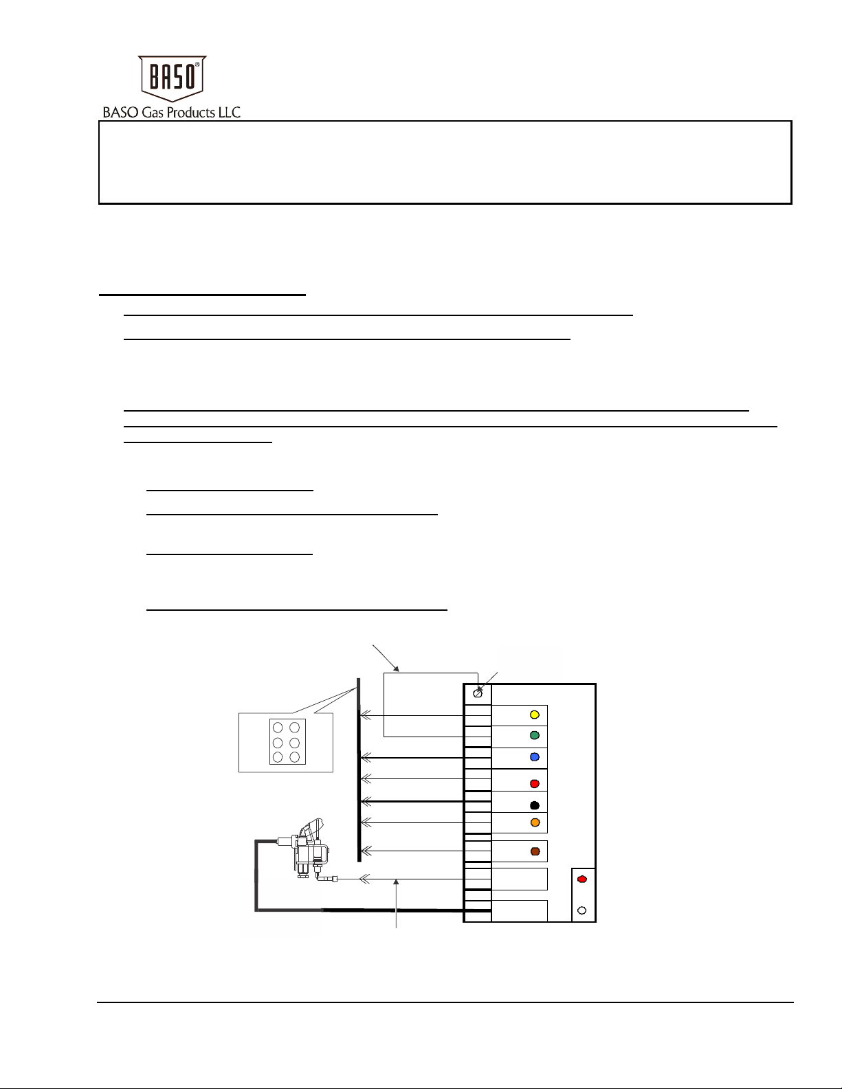
4. Connect the following Wires and Wire Harness to the BGN891 Ignition Control:
4.1 Plug in the Wire Harness:
4.2 Connect the “GREEN” ground wire to frame:
Connect the BGN (6 pin) Wire Harness into the existing wire harness.
Connect the #6 Ring Terminal to one of the mounting
screws from Step 3.
4.3 Connect the SENSE wire:
Connect the existing WHT or ORG SENSE wire coming from the appliance to
the short ORG jumper wire with the 3/16” Q.C. terminal located on the SENSE terminal of the BGN891
ignition.
4.4 Install the ORG SPARK wire (thick insulation):
Install the 1/4” Q.C. Insulated Terminal (provided in Kit)
onto the SPARK Wire, and connect it to the SPARK terminal on the BGN891 Ignition Control.
BURNER GROUND WIRE (CONNECT TO THE FRAME OR MOUNTING SCREW)
BASO
BGN891-1C
MOUNTING SCREW
Ignition
LABEL
GND
YEL
GND
GRN
24V
BLU
BLWR (N.O.)
RED
120V LINE
BLK
VALVE
ORG
TH
BRN
SENSE
SPARK
BASO
BGN891
IGNITION CONTROL
LED
SEE FLASH CODE
TABLES 1 AND 2
6-PIN CONNECTOR
AND HARNESS
BURNER/IGNITER
THICK
INSULATION
WIRE
1
2
3
PILOT
Pilot
Burner/Igniter
Assembly
2
4
5
6
4
5
6
3
1
SHORT ORG JUMPER WIRE WITH
3/16” SPADE QC TERMINAL
GRN
YEL
GRN
BLU
RED
BLK
ORG
BRN
WHT/ORG
ORG
Figure 1: BGN891 Wiring Diagram
© 2012 BASO Gas Products 1
Part No. BASO-INS-BGN891, Rev. C www.baso.com
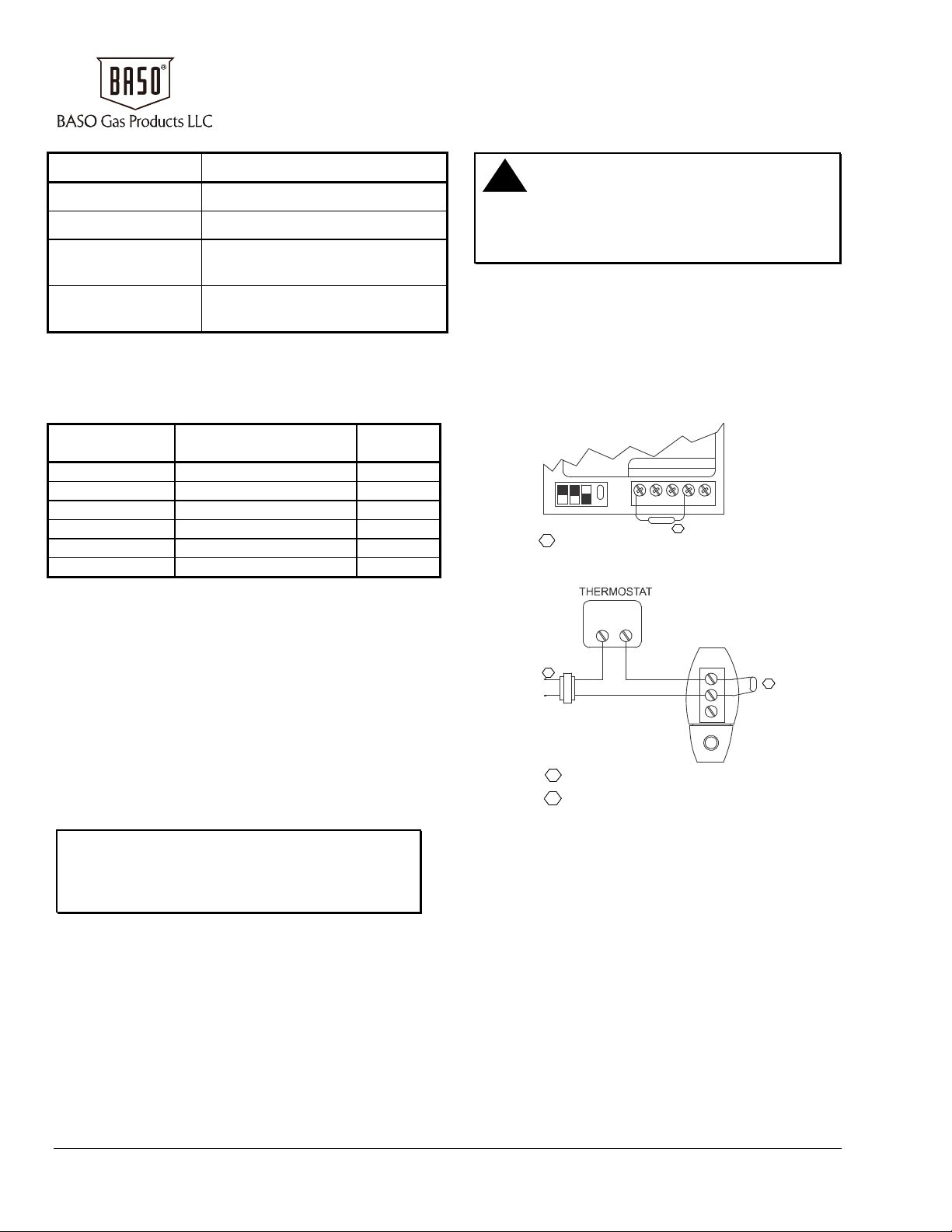
Table 1: Normal Operating LED Indications
Green LED Definition
Rapid Blinking Spark Active
Steady On Flame Detected, Main Burner On
0.5 Second On/Off Pre-purge, Interpurge or Postpurge
0.5 Second On
Retry or Recycle Time
4.5 seconds Off
Table 2: Error Code LED Indications
Error Codes Blink 0.25 Second On/Off
then Pause 1.0 Second and Repeat.
Led Light Error Definition Error
Type
Blinks 1 Time No Flame in Trial Time Lockout
Blinks 2 Times Flame Sense Circuit Lockout
Blinks 3 Times Pilot/Main Valve Circuit Lockout
Blinks 4 Times Flame Loss Lockout
Blinks 7 Times Ground or Internal Lockout
Steady On Line Voltage/Frequen cy Standby
RES100A-600 Resistor Installation
Instructions
Application
The RES100A-600 Resistor is a direct replacement
for Honeywell 202764BAC Resistor and is used in
certain applications to ensure compatibility with
power-stealing thermostats. The RES100A-600 is a
1000 ohm, 3 watt resistor.
Installation
When Installing this Product…
IMPORTANT: Only qualified personnel
should install or service BASO Gas Products®.
These instructions are a guide for such personnel.
Carefully follow all instructions for the appliance.
!
CAUTION: Electrical Hazard.
Can Cause Electrical Shock or Equipment
Damage.
Disconnect power supply before installing resistor.
To Install the Resistor
1. Loosen terminal screws as shown in the
application drawing.
2. Slide the resistor leads under the terminal
screws and tighten the screws.
3. Turn on the system power.
4. After installation is complete, check out product
operation as provided in these instructions.
ST9120A-G
CGYWR
1
DISCONNECT POWER SUPPLY BEFORE INSTALLATION
1
Figure 1: Connect Resistor to ST9141 Fan Timer Terminals C and W
RW
TACO ZONE VALVE
1
L1
(HOT)
L2
1
POWER SUPPLY PROVIDES DISCONNECT MEANS AND
OVERLOAD PROTECTION AS REQUIRED.
2
BEND RESISTOR AWA Y FROM ZONE V A LVE CASE
TO PREVENT SHORTING.
1
2
3
RESISTOR
2
Figure 2: Connect Resistor to Taco Zone Valve Terminals 1 and 2
Note: If furnace fails to start, remove flapper and clean before re-starting.
1007 South 12th Street
PO Box 170
Watertown, WI 53094 www.baso.com
1-877-227-6427 (1-877-BASOGAS) Published in U.S.A.
2 BGN891 Direct Spark Ignition Control Installation Instructions
 Loading...