

Page 1
Installation Instructions BGH
Issue Date October 4, 2010
BGH2UNCNTRLHT-01 Universal
Hot Surface Ignition Control
Application
The BASO Gas Products BGH2UNCNTRLHT-01
Universal Series Hot Surface Ignition (HSI) control is
microprocessor based with timed ignition and suited
for replacement or new applications. Applications for
hot surface ignition modules include agricultural
equipment, space heaters, furnaces,
residential/commercial boilers, water heaters, pool
and spa heaters, and a variety of other commercial
cooking equipment.
This control includes a 5 position DIP switch allowing
up to 32 programmable pre-defined timing selections
to retrofit other Hot Surface Ignitions with flame
sensing rectification, such as: Johnson Controls,
Honeywell, White Rodgers, Fenwal, and
Robertshaw.
The BGH2UNCNTRLHT-01 works with single-rod or
dual-rod sensing to prove a flame. The control has a
continuous and precise monitoring of the HSI
element, wiring, and gas valve, shutting down in the
event of a failure. For a complete listing of
specifications, refer to the Technical Specifications
section.
Installation
IMPORTANT: Only qualified personnel
should install or service BASO Gas Products®.
These instructions are a guide for such personnel.
Carefully follow all instructions for the appliance.
IMPORTANT: Make all gas installations in
accordance with applicable local, national, and
regional regulations.
!
WARNING: Risk of Explosion or Fire.
Do not install the control in an area that is exposed
to water (for example, dripping, spraying, rain). Do
not use the control if it has been exposed to water.
Exposure to water may cause malfunction and can
lead to an explosion or fire and may result in
severe personal injury or death.
© 2010 BASO Gas Products 1
Part No. BASO-INS-BGH, Rev. - www.baso.com
Page 2

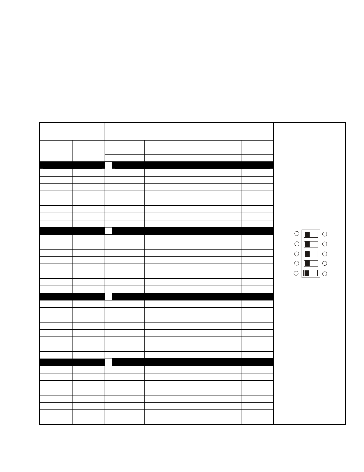
Table 1: BGH2UNCNTRLHT-01 Universal Cross Reference
Switch
Positions
ON
Switch
Positions
OFF
none 1,2,3,4,5
5 1,2,3,4
4 1,2,3,5
4,5 1,2,3
3 1,2,4,5
3,5 1,2,4,
White-Rodgers Robershaw Honeywell Fenwal
50E47-150 to 159
50E47-350 to 359
50E47-140 to 149
50E47-340 to 349
50F47-150 to 159
50F47-350 to 359
50F47-140 to 149
50F47-340 to 349
50E47-170 to 179
50E47-370 to 379
50F47-170 to 179
50F47-370 to 379
50E47-160 to 169
50E47-360 to 369
50F47-160 to 169
50F47-360 to 369
HS780-34NL-306A(a,c)
HS780-34NL-308A(a,c)
HS780-34NL-312A(c,d)
HS780-34NR-306A(a,c)
HS780-34NR-308A(a,c)
HS780-34NR-312A(c,d)
HS780-17NR-306A(a,b)
HS780-17NR-308A(a,b)
HS780-17NL-308A(a,b)
― ― ―
― ― ―
― ― ―
― ―
05-356265-153(d,g)
05-356265-154(d,g)
S89H1011(a,c)
S89G1013(a,c)
S89G1021(c,d)
―
S89H1029(c,d)
S89G1047(a,c)
05-356265-053(c,d)
―
05-356265-054(c,d)
05-356265-055(c,d)
S8910U
S890H1010(a,f)
3,4 1,2,5 ― ―
S890G1011(a,f)
S890H1028(d,f)
―
S890G1029(d,f)
S890G1037(a,f)
3,4,5 1,2 ― ― ― ―
Note: For timing parameters see Table 2.
(a) The BGH2UNCNTRLHT-01 Universal and the referenced control ignition trial times are different; however, the
ignition trial time is within the design tolerance of the referenced control.
(b) The BGH2UNCNTRLHT-01 Universal between trial purge time is longer than that of the referenced control.
(c) The BGH2UNCNTRLHT-01 Universal between trial purge and igniter warmup times is longer than those of the
referenced control.
(d) The BGH2UNCNTRLHT-01 Universal ignition trial time is shorter than that of the referenced control. Be sure
to observe appliance operation to assure reliable performance.
(e) The BGH2UNCNTRLHT-01 Universal pre-purge time is longer than that of the referenced control
(f) The BGH2UNCNTRLHT-01 Universal pre-purge and between trial purge times are longer than those of the
referenced control.
(g) The BGH2UNCNTRLHT-01 Universal pre-purge, between trial purge, and igniter warmup times are longer
than those of the referenced control.
2 BGH2UNCTRLHT-01 Universal Hot Surface Ignition Control Installation Instructions
Page 3

Table 1: BGH2UNCNTRLHT-01 Universal Cross Reference
Switch
Positions
ON
Switch
Positions
OFF
2 1,3,4,5
2,5 1,3,4
2,4 1,3,5
2,4,5 1,3
2,3 1,4,5
2,3,5 1,4
White-Rodgers Robershaw Honeywell Fenwal
50E47-130 to 139
50E47-330 t 339
50E47-120 to 129
50E47-320 to 329
50F47-130 to 139
50F47-330 to 339
50F47-120 to 129
50F47-320 to 329
― ― ―
― ― ―
― ― ―
05-356225-153(d,g)
― ―
05-356225-154(d,g)
05-356225-155(d,g)
50E47-110 to 119
50E47-310 to 319
50F47-110 to 119
― ― ―
50F47-310 to 319
50E47-101 to 109
50E47-301 to 309
50F47-101 to 109
50F47-301 to 309
HS780-17NL-108A(a) ―
05-356225-053(c,d)
05-356225-054(c,d)
05-356225-055(c,d)
8910U
2,3,4 1,5 ― ―
S890D1006(a,e)
―
S890C1007(a,e)
S89D1002(a)
2,3,4,5 1 ― HS780-34NL-108A(a)
S89C1004(a)
S89J1008(a)
―
S89C1012(a)
1 2,3,4,5
50E47-50 to 59
50E47-250 to 259
― ― ―
Note: For timing parameters see Table 2.
(a) The BGH2UNCNTRLHT-01 Universal and the referenced control ignition trial times are different; however, the
ignition trial time is within the design tolerance of the referenced control.
(b) The BGH2UNCNTRLHT-01 Universal between trial purge time is longer than that of the referenced control.
(c) The BGH2UNCNTRLHT-01 Universal between trial purge and igniter warmup times is longer than those of the
referenced control.
(d) The BGH2UNCNTRLHT-01 Universal ignition trial time is shorter than that of the referenced control. Be sure
to observe appliance operation to assure reliable performance.
(e) The BGH2UNCNTRLHT-01 Universal pre-purge time is longer than that of the referenced control
(f) The BGH2UNCNTRLHT-01 Universal pre-purge and between trial purge times are longer than those of the
referenced control.
(g) The BGH2UNCNTRLHT-01 Universal pre-purge, between trial purge, and igniter warmup times are longer
than those of the referenced control.
BGH2UNCTRLHT-01 Universal Hot Surface Ignition Control Installation Instructions 3
Page 4

Table 1: BGH2UNCNTRLHT-01 Universal Cross Reference
Switch
Positions
ON
1,5 2,3,4
Switch
Positions
OFF
White-Rodgers Robershaw Honeywell Fenwal
50E47-40 to 49
50E47-240 to 249
50F47-50 to 59
1,4 2,3,5
1,4,5 2,3
50F47-250 to 259
50F47-40 to 49
50F47-240 to 249
50E47-70 to 79
1,3 2,4,5
50E47-270 to 279
50F47-70 to 79
HS780-34NL-304A(c)
50F47-270 to 279
50E47-60 to 69
1,3,5 2,4
50E47-260 to 269
50F47-60 to 69
HS780-17NL-304A(b) ―
50F47-260 to 269
1,3,4 2,5 ― ―
― ― ―
― ― ―
― ―
S89H1003(c)
S89G1005(c)
05-356265-151(a,g)
05-356265-152(a,g)
―
05-356265-051(a,c)
05-356265-052(a,c)
S8910U
S890G1003(f)
S890H1002(f)
1,3,4,5 2 ― ― ― ―
1,2 3,4,5
1,2,5 3,4
1,2,4 3,5
1,2,4,5 3
50E47-30 to 39
50E47-230 to 239
50E47-20 to 29
50E47-220 to 229
50F47-30 to 39
50F47-230 to 239
50F47-20 to 29
50F47-220 to 229
― ― ―
― ― ―
― ― ―
― ―
05-356225-151(a,g)
05-356225-152(a,g)
Note: For timing parameters see Table 2.
(a) The BGH2UNCNTRLHT-01 Universal and the referenced control ignition trial times are different; however, the
ignition trial time is within the design tolerance of the referenced control.
(b) The BGH2UNCNTRLHT-01 Universal between trial purge time is longer than that of the referenced control.
(c) The BGH2UNCNTRLHT-01 Universal between trial purge and igniter warmup times is longer than those of the
referenced control.
(d) The BGH2UNCNTRLHT-01 Universal ignition trial time is shorter than that of the referenced control. Be sure
to observe appliance operation to assure reliable performance.
(e) The BGH2UNCNTRLHT-01 Universal pre-purge time is longer than that of the referenced control
(f) The BGH2UNCNTRLHT-01 Universal pre-purge and between trial purge times are longer than those of the
referenced control.
(g) The BGH2UNCNTRLHT-01 Universal pre-purge, between trial purge, and igniter warmup times are longer
than those of the referenced control.
4 BGH2UNCTRLHT-01 Universal Hot Surface Ignition Control Installation Instructions
Page 5

Table 1: BGH2UNCNTRLHT-01 Universal Cross Reference
Switch
Positions
ON
Switch
Positions
OFF
White-Rodgers Robershaw Honeywell Fenwal
50E47-10 to 19
1,2,3 4,5
50E47-210 to 219
50F47-10 to 19
― ― ―
50F47-210 to 219
50E47-1 to 9
1,2,3,5 4
50E47-201 to 209
50F47-1 to 9
HS780-17NL-104A
HS780-17NR-104A
―
05-356225-051(a,c)
05-356225-052(a,c)
50F47-201 to 209
1,2,3,4 5 ― ― S8910U ―
1,2,3,4,5 none ― HS780-34NR-104A
S89C1046
S89C1103
―
Note: For timing parameters see Table 2.
(a) The BGH2UNCNTRLHT-01 Universal and the referenced control ignition trial times are different; however,
the ignition trial time is within the design tolerance of the referenced control.
(b) The BGH2UNCNTRLHT-01 Universal between trial purge time is longer than that of the referenced control.
(c) The BGH2UNCNTRLHT-01 Universal between trial purge and igniter warmup times is longer than those of
the referenced control.
(d) The BGH2UNCNTRLHT-01 Universal ignition trial time is shorter than that of the referenced control. Be
sure to observe appliance operation to assure reliable performance.
(e) The BGH2UNCNTRLHT-01 Universal pre-purge time is longer than that of the referenced control
(f) The BGH2UNCNTRLHT-01 Universal pre-purge and between trial purge times are longer than those of the
referenced control.
(g) The BGH2UNCNTRLHT-01 Universal pre-purge, between trial purge, and igniter warmup times are longer
than those of the referenced control.
BGH2UNCTRLHT-01 Universal Hot Surface Ignition Control Installation Instructions 5
Page 6
Replacing the Existing Ignition Control
7. Mount the new control with #6 sheet metal or
!
CAUTION: Risk of Electric Shock.
Disconnect power supply before making electrical
connections to avoid electric shock.
!
WARNING: Risk of Explosion or Fire.
Shut off the gas supply at the main manual shutoff
valve before installing or servicing the control.
Failure to shut off the gas supply can result in the
release of gas during installation or servicing, which
can lead to an explosion or fire, and may result in
severe personal injury or death.
!
WARNING: Risk of Explosion, Fire, or
Electric Shock. Label all wires before they are
disconnected when replacing or servicing the
control. Wiring errors can cause improper or
dangerous operation and may result in an explosion,
fire, or electric shock leading to severe personal
injury or death.
To remove the existing ignition control:
1. Shut off power to the appliance.
2. Turn off the gas at the main manual shutoff valve
adjacent to the appliance. (If the manual shutoff
valve services more than one appliance, be sure
to light the other pilots before leaving the
installation.)
3. Label each wire with the correct terminal
designation prior to disconnection.
machine screws through the mounting holes in
the enclosure.
8. Refer to the Wiring section for electrical
connections and wiring diagrams. Perform the
Checkout section before leaving the installation.
9. Check all wiring for proper connections and make
sure your system is properly grounded.
Wiring
!
WARNING: Risk of Explosion or Fire.
Locate all safety, limit, and operating controls in
series with the thermostat terminal (TH) on the
ignition control. Improper installation may cause gas
leaks, which can lead to an explosion or fire and
may result in severe personal injury or death.
Refer to Figure 1 and Figure 2 for wiring diagrams. All
wiring should be in accordance with the National
Electrical Code (NEC) and all other local codes and
regulations.
Check the voltage rating marked on the control and
make sure it is suited to the application. Use a Class 2
transformer capable of providing 24 VAC under
maximum load, including valves. A transformer having
excessive primary impedance due to poor coupling
affects the ignition potential.
The control is supplied with a jumper wire between
Sense (terminal 10) and 120/240V Hot HSI
(terminal 7). With the jumper in, flame is sensed
through the high voltage HSI (Hot Surface Igniter)
wire. The jumper must be removed for external flame
sense and the sense electrode wired to the Sense
terminal.
4. Disconnect the wires from the existing control.
5. Remove the screws holding the ignition control to
the valve (if direct valve-mount model) or remove
the screws holding the control to the appliance
chassis (if foot-mount model).
6. Remove the old ignition control and discard.
IMPORTANT: Do not mount the control where
it can be exposed to direct infrared radiation from the
main burner or to temperatures in excess of the
maximum product temperature rating.
6 BGH2UNCTRLHT-01 Universal Hot Surface Ignition Control Installation Instructions
!
WARNING: Risk of Electric Shock.
Before applying power to the control, connect all
wires properly to the controller. Verify the controller
is properly grounded. Failure to follow this procedure
can cause electric shock and may result in severe
personal injury or death.
Page 7

Chassis or
Frame Ground
GND
GND
(24V)
(BURNER)
12
GND
3
120/240V
NEUTRAL
(VALVE)
L2
4
HSI
5
120/240V
HOT
L1
6
HSI
UNIVERSAL
ONLY
24V
(TH)
7
MARK
POS
VALVE
ON
1
89
2
3
4
5
Wire
Nut
Thermostat
SENSE
(REMOTE)
10
4
Burner
Ground
5
HSI
(Hot Surface Igniter)
Combination
3
Gas Valve
24V
Class 2
2
Transformer
L1 (Hot)
High Temp
Limit
1
Power Supply. Provides disconnect means and overload protection as required.
The controls 24V circuit must not be in the ground leg to the transformer.
2
3
Alternate location for limit to the controller.
4
For Internal Flame Sense circuits, check that the jumper wire is connected between HSI HOT
L2 (Neutral)
1
(terminal 7) and SENSE REMOTE (terminal 10).
5
Ensure the burner ground is in the pilot flame (3/8” [9mm] to 1/2” [12.7mm]) for proper sensing signal.
Figure 1: Typical Wiring for BGH2UNCNTRLHT-01 with Internal Flame Sense
BGH2UNCTRLHT-01 Universal Hot Surface Ignition Control Installation Instructions 7
Page 8

Universal
1
8
2
3
4
5
Only
MARK
POS
ON
Thermostat
VALVE
9
SENSE
(REMOTE)
10
Burner
Ground
5
HSI
(Hot Surface Igniter)
Flame
Sensor
4
GND
1
Chassis or
Frame Ground
(BURNER)
GND
(24V)
2
120/240V
NEUTRAL
GND
(VALVE)
L2
34
HSI
5
120/240V
HOT
L1
HSI
67
24V
(TH)
Combination
3
Gas Valve
24V
Class 2
2
Transformer
L1 (Hot)
High Temp
Limit
1
Power Supply. Provides disconnect means and overload protection as required.
2
The controls 24V circuit must not be in the ground leg to the transformer.
3
Alternate location for limit to the controller.
4
Check for the sensor tip of the Remote Flame Sensor is 3/8” (9 mm) to 1/2” (12.7 mm)
L2 (Neutral)
1
in the flame for proper sensing signal.
5
Ensure the burner ground i s in the pil ot flame (3/8” [9mm] to 1/2” [12.7mm]) for proper sensing si gnal.
Figure 2: Typical Wiring for BGH2UNCNTRLHT-01 with Remote Flame Sense.
8 BGH2UNCTRLHT-01 Universal Hot Surface Ignition Control Installation Instructions
Page 9
Setup and Adjustments
Select Dip Switch Positions
A 5 position dip switch is provided on the controller to
allow for field programming of 1 to 32 possible predefined sets of timing sequences. Select a predefined
timing sequence from Table 1 and then set the dip
switches on the control.
Table 2: BGHUNCNTRLHT-01 Universal HSIC
Parameters/Dip Switch Positions
5 Position Dip
Switch Settings
HSIC Parameters
To change the settings, remove power from the circuit
board, change settings and re-apply power to the
circuit board.
The dip switches remain active until 10 consecutive
power cycles occur without a change in any dip switch
setting. Once this occurs, dip switches become
inactive and cannot further be used to change timing
specifications.
ON OFF
None 1,2,3,4,5 45 30 90 7 3
5 1,2,3,4 17 30 90 7 3
4 1,2,3,5 45 17 77 7 3
4,5 1,2,3 17 17 77 7 3
3 1,2,4,5 45 None 60 7 3
3,5 1,2,4 17 None 60 7 3
3,4 1,2,5 34 32 96 7 3
3,4,5 1,2 34 None None 7 3
2 1,3,4,5 45 30 None 7 1
2,5 1,3,4 17 30 None 7 1
2,4 1,3,5 45 17 None 7 1
2,4,5 1,3 17 17 None 7 1
2,3 1,4,5 45 None None 7 1
2,3,5 1,4 17 None None 7 1
2,3,4 1,5 34 32 None 7 1
2,3,4,5 1 34 None None 7 1
1 2,3,4,5 45 30 90 4 3
1,5 2,3,4 17 30 90 4 3
1,4 2,3,5 45 17 77 4 3
1,4,5 2,3 17 17 77 4 3
1,3 2,4,5 45 0 60 4 3
1,3,5 2,4 17 0 60 4 3
1,3,4 2,5 34 32 96 4 3
1,3,4,5 2 34 0 0 4 3
1,2 3,4,5 45 30 None 4 1
1,2,5 3,4 17 30 0 4 1
1,2,4 3,5 45 17 0 4 1
1,2,4,5 3 17 17 0 4 1
1,2,3 4,5 45 0 0 4 1
1,2,3,5 4 17 0 0 4 1
1,2,3,4 5 34 32 0 4 1
1,2,3,4,5 None 34 0 0 4 1
*Warmup time is timed ignition.
*Warmup
(Sec.) (Sec.) (Sec.) (Sec.) #
Pre-
Purge
Between
Purge
Ignition
Trial Time
No. of
Trials
OFF
ON
1
2
3
4
5
Figure 3: 5 Position
Dip Switch
Switch settings shown
with all 5 switches in the
OFF positions.
BGH2UNCTRLHT-01 Universal Hot Surface Ignition Control Installation Instructions 9
Page 10

Checkout
!
WARNING: Risk of Explosion or Fire.
Verify that there are no gas leaks by testing with
appropriate equipment. Never use a match or lighter
to test for the presence of gas. Failure to test
properly can lead to an explosion or fire and may
result in severe personal injury or death.
Make sure all components function properly by
performing the following checks.
1. Before starting the appliance, perform a safety
inspection of piping, burners and venting. Check
for gas leaks, etc. Check all wiring for proper
connections. Be sure the system is properly
grounded, including ground connection to the
burner ground (Terminal 1).
2. With the gas and thermostat off, turn on power to
the appliance.
3. Turn the thermostat to a high setting and verify
that the control goes through the operating
sequence to a shutoff condition.
Note: The burner does not light because the
gas is off.
4. Turn off the thermostat.
5. Turn on the gas and purge gas lines of all air.
6. Check for gas leaks on all pipe joints upstream of
the gas valve with a soap solution.
7. Turn the thermostat to the highest setting and
verify successful ignition and a normal run
condition for at least 5 minutes. If the appliance
fails to run, see the Troubleshooting section.
8. Check for gas leaks on all pipe joints
downstream of the gas valve with a soap
solution.
9. Turn the thermostat down for at least 30 seconds
and then back up again. Verify successful
ignition at least five times.
Operation
Operating Mode Definitions
The following definitions describe the operating
conditions.
• Pre-Purge: Initial time delay between the
thermostat contact closure (Call for Heat) and the
HSI (Hot Surface Igniter) and pilot valve are
activated. The controls “LED” will flash green
“ON” and “OFF” at 0.5 s rate.
• Igniter Warmup (Timed Ignition): The time
allowed for the hot surface igniter to heat up
before the Trial-For-Ignition sequence is
activated. The controls “LED” will flash green
“ON” and “OFF” at 0.5 s rate.
• Trial-For-Ignition (TFI): This is the total time the
pilot valve and hot surface igniter are “ON”
(energized), and flame sense sequence is
activated in an attempt to light the pilot. The
control attempts to prove flame within the TrialFor-Ignition time. The “LED” will flash green at
0.5 second “ON” and 0.5 second “OFF”.
• Flame Sensed: With a flame present, a current
path is connected between the “Igniter” and “Main
Burner” ground on “Internal Flame Sense”
Models, or between a “Flame Sense Rod” and
“Main Burner” ground on “Remote Flame Sense”
Models. The “Main Burner” and gas valve remain
on as long as a flame is present. When the
thermostat opens (Call for Heat ends) the control
turns “OFF” (de-energizes) the gas valve, there by
extinguishing the flame.
• 100% Shutoff (Flame Not Sensed) With 1
Ignition Trial (Bad Flame/No Flame): If the
control does not prove the presence of pilot
burner flame within the “Trial-For-Ignition” time,
then both gas valve relays are turned “OFF”
(de-energized) and the control goes into Lockout
mode. See Troubleshooting Guide for possible
faults.
10. Return the thermostat to a normal temperature
setting before leaving the installation.
!
WARNING:
The control module can not be serviced by user. If
any faults are detected, the control module must be
replaced. If control module has been opened or any
attempts to repair are done, the warranty is void.
10 BGH2UNCTRLHT-01 Universal Hot Surface Ignition Control Installation Instructions
Page 11

• 100% Shutoff (Flame Not Sensed) With 3
Ignition Trials (Bad Flame/No Flame):
If the control does not prove the presence of
igniter flame within the “Trial-For-Ignition” time,
then the relay gas valve is turned “OFF” (deenergized) and the control initiates a time delay of
“Between-Trial-Purge” time, and then followed by
another ignition sequence. If flame is not sensed,
an ignition sequence is repeated until the total
number of Trials-for-Ignition are completed. If
flame is still not sensed then all relays are turned
“OFF” (de-energized) and the control goes into
lockout mode. See Troubleshooting Guide for
possible faults.
• Number of Ignition Trials: If 100% shutoff
occurs and the control was set up for 3 ignition
trials, the control will delay for the “Between-TrialPurge” time and begin another Trial-For-Ignition
sequence.
• Run (Operation): Once an igniter flame is proven
then the hot surface igniter is turned “OFF”
(de-energized) and the gas valve is turned “ON”
(energized). The gas valve remains “ON”
(energized) until the thermostat is satisfied (Call
for Heat).
• Flameout (Flame Lost): After a flame is
established, and a loss of proven flame occurs
during burner operation the gas valve is turned
“OFF” (de-energized) and the control will delay for
the Between-Trial-Purge time before it begins
another ignition sequence.
• Lockout: An internal or external fault has caused
the control to de-energize the hot surface igniter
circuit and valve relays. The thermostat contacts
must be opened for a minimum of 30 seconds and
then closed to begin another ignition sequence.
Sequence of Operation
The heating cycle begins when a call for heat from the
thermostat supplies 24VAC to the 24V (TH) terminal 8
on the Control which starts an ignition sequence. After
a 1 second maximum diagnostic period, the prepurge
cycle starts.
During the Pre-Purge cycle the gas valve relays and
HSI (Hot Surface Igniter) remain “OFF” (deenergized). The controls “LED” will flash green “ON”
and “OFF” at 0.5 s rate. At the end of the Prepurge
time, the control begins the igniter warmup cycle.
Igniter Warmup (Timed Ignition) cycle turns “ON”
(energizes) both HSI relays and remains on for a set
time. The controls “LED” will flash green “ON” and
“OFF” at 0.5 s rate. At the end of the Igniter Warmup
time, the control begins the Trial-For-Ignition cycle.
Trial-For-Ignition cycle turns “ON” (energizes) the
gas valve relay and the hot surface igniter remains
“ON” (energized) to allow a flame to be established.
The control attempts to prove flame within the TrialFor-Ignition time. The “LED” will flash green at 0.5 s
“ON” and 0.5 s “OFF”.
Once, a flame is detected a current path is connected
between the “Igniter” and “Main Burner” ground on
“Internal Flame Sense” Models, or between a “Flame
Sense Rod” and “Main Burner” ground on “Remote
Flame Sense” Models and the hot surface igniter is
turned “OFF” (de-energized) while the gas valve
remains “ON” (energized) as long as a flame is
present. The control will remain in this state until the
igniter flame is lost or the call for heat ends.
If igniter flame is not detected or flame lost, the gas
valve is turned “OFF” (de-energized) and the controls
go into 100% lockout for models having only 1 ignition
trial or will restart the Ignition Sequence for Models
having 3 ignition trials. The control will wait for the
“Between-Purge” time while blinking the “LED” at the
end of each 15 seconds during the Between-Purge
cycle. When the “Between-Purge” time cycle is
completed a new Ignition sequence will begin.
When the “Call for Heat” ends, the thermostat opens
and the control turns “OFF” (de-energizes) the gas
valve, there by extinguishing the flame.
Table 2: LED Indications during Normal Operation
Green Flash Code Flash Code Indication
Flame detected,
Steady On
Good flame,
Main burner on
0.5 Second On
0.5 Second Off
2 Continuous
Quick Flashes
Pre-purge,
Between trial purge,
Igniter warmup
Flame detected,
Weak flame,
Main burner on
BGH2UNCTRLHT-01 Universal Hot Surface Ignition Control Installation Instructions 11
Page 12

Power On
Initialize software,
test ROM, RAM and E2
get voltage and
frequency
OK
Check for flame
sense stuck on
OK
Do pre-purge delay
blink LED .5 sec. on/off
continuously check
gas valve feedback to
assure valve is off
OK
Perform hot surface
igniter short test, turn
on hot surface igniter
OK
Continuously check
gas valve feedback and
HSI current
OK
After required delay
turn on gas valve
Error
Error
Error
Error
LockoutLockout
Error
LockoutLockout
LockoutLockout
LockoutLockout
LockoutLockout
Note:
If the thermostat opens,
the control will turn off valves
and returns to the idle state.
Test ROM, RAM, E2, and line.
Test gas valve relay
feedback voltage.
Good flame LED on solid.
Weak flame LED 2 blink.
Flame
detected?
Wait 0.1 second
Flame bad
7 readings
OK
No
Ye s
LockoutLockout
Ye s
No
FLAME LOST, TURN
OFF GAS VALV E AND
TRY TO RELIGHT
Continuously check
gas valve feed back and
HSI current
HSI
timeout?
Gas valve
No
timeout?
Check flame, read
flame detect circuit
7X @ 100 MSEC apart
Flame
detected?
Turn off all relays.
Do between trial purge
blink LED .5 sec. On/off.
Continuously check
gas valve feedback to
assure valve off.
Ye s
No
Ye s
No
Ye s
Turn off HSI
RELIGHT
Note:
If the controller is flashing an error code, the control
will be in l ockout. The contr oller will stay in lockout and continue
flashing an error code until power is cycled. If an error code repeats,
then see Table 3 Troubleshooting Guide to determine
the problem.
Error Codes
Flame Error
Gas Valve Error
Line Voltage/Frequency Error
Processor Errors
Red Flash Code
1 Blink
3 Blinks
4 Blinks
5 Blinks
Error Type
Lockout
Lockout
Stand By
Lockout
Figure 4: Sequence of Operation Flow Chart
12 BGH2UNCTRLHT-01 Universal Hot Surface Ignition Control Installation Instructions
Page 13

Troubleshooting
!
WARNING: Risk of Personal Injury.
Do not place face, hands, or other parts of the body
in or near the burner area when the LED is flashing
(recycle mode). When the LED is flashing, the
control may at any time (while in the recycle mode)
re-energize the burner control system and ignite the
burner which may result in electric shock from
contact with the electrode or severe burn injury from
firing of the burner.
If the system does not function properly, determine
the cause using the procedures in this section.
Before proceeding with troubleshooting the system,
check the following.
Preliminary Checks
Are all mechanical and electrical connections tight?
Is the system wired and ground correctly?
Is gas inlet pressure per manufacturer’s
specifications?
Is the system powered?
Is the thermostat calling for heat?
LED Error Indications
If the control module internal diagnostics detect a
fault it will go to lockout. The hot surface igniter and
gas valve will be turned off. The LED will flash an
error code 0.25 seconds “on” and 0.25 seconds “off"
for each count of the error code with 1 second off
between codes. The control will remain in this
condition until power is removed by turning off the call
for heat. The flashing LED error code indicates a
problem with wiring, or a component not working, or
the control module is faulty. Try to recycle the power
on the control. If the error repeats then see Table 3
Troubleshooting Guide to determine the problem.
Table 3: BGH2UNCNTRLHT-01 Universal Series HSI Control Troubleshooting Guide
RED
LED
Flash
Code
No LED
“ON”
1
3
4
5
NOTE: If Troubleshooting Guide has been used, and the Control Module is flashing a RED LED FLASH ERROR CODE, then
the Control Module may be faulty. Replace the Control Module.
ERROR
Indication
No Power
Flame Sense
Circuit
GAS Valve
Circuit
Line Voltage
/Freq. Circuit
Internal
Control
Troubleshooting Guide
1. Check for 24 volts on terminal 8 (24V TH) and terminal 2 (24V GND).
2. Check for “OPEN” limits wired between terminal 8 (24V TH) and the 24 volt secondary
coil winding of the controls transformer.
3. Check for 24 volts on the secondary coil winding of the controls transformer.
1. Check if gas is turned “ON”.
2. Check incoming power (NEUTRAL) wiring to terminal 4 (L2 NEUTRAL).
3. Check Igniter wiring to terminal 7 (HSI HOT) and terminal 5 (HSI NEUTRAL).
4. Check Flame Sensor tip is in the flame. For proper sensing the rod tip must be 3/8”
(10mm) to 1/2” (13mm) in the flame.
5. Check the Burner Ground is in the pilot flame. For proper sensing, the burner ground
must be 3/8” (10 mm) to 1/2” (13 mm) in the flame and is connected to terminal 1
(BURNER GND).
6. For Internal Flame Sense circuits, check “JUMPER WIRE” is on
terminal 10 (SENSE REMOTE) and terminal 7 (HSI HOT).
7. For a Remote Flame Sense circuit; check that the Jumper Wire is removed from Terminal
10 (SENSE REMOTE) and Terminal 7 (HSI HOT). Also, check wiring of the Remote
Flame Sensor to Terminal 10 (SENSE REMOTE).
1. Check “GAS VALVE” wiring to terminal 9 (VALVE) and terminal 3 (VALVE GND).
2. Check for 24 volts at the coil of the “GAS VALVE”.
1. Check Burner Ground wiring to terminal 1 (BURNER GND).
2. Check incoming power Line 1 (HOT) (120 or 240 VAC) wiring to terminal 6(L1 HOT).
1. Review all ground connections.
2. Software error – Restart control module.
BGH2UNCTRLHT-01 Universal Hot Surface Ignition Control Installation Instructions 13
Page 14

Turn on power
and gas.
Close thermostat
contacts.
Module LED
did not light?
No
Module LED
blinks green?
Ye s
Igniter didn’t turn
on during igniter
warmup mode?
No
Ye s
No
Ye s
LED blinks
1, 3, or 5 quick red
flashes, then
pause?
Ye s
Replace
module.
120 VAC
between HSI (HOT)
and L2 (NEUT)
during igniter
warmup?
No
Replace
module.
24V between
24V and 24V(GND)
terminals?
Ye s
Replace
module.
No
LED blinks
2 quick red
flashes, then
pause?
Ye s
Check wiring to igniter.
Check igniter for short
or malfunction and
replace if necessary.
Ye s
Check wiring to igniter.
Check igniter and replace
if necessary.
No
No
Check transformer,
thermostat and wiring.
Repair or replace as needed.
LED blinks
4 quick red
No
flashes, then
pause?
Ye s
Check line
voltage.
Check shutoff valves are on.
Check wiring to main valve.
Check tubing is clear.
If all OK, replace main valve.
Replace
module.
24 VAC
Main burner
failed to light
during trial for
ignition?
No
After burner
is lit, does valve
turn off and start
new cycle?
No
Control is
operating
Ye s
Ye s
Main flame
in contact with
Adjust main flame size
or igniter position.
LED blinks
3 quick red
flashes, then
pause?
Ye s
Replace
module.
igniter?
No
No
Ye s
grounded to GND
Assure main burner
is properly grounded.
between VALVE
and VALVE (GND)
terminals during trial
for ignition?
Replace
module.
Main burner
(BURNER)?
No
No
Ye s
size or position, adjust
Ye s
Remote
flame sense?
Check wiring to
REMOTE (SENSE) terminal.
If OK, replace module.
Gas at
main burner?
Adjust burner flame
igniter position, or
replace main burner.
Ye s
normally.
Figure 5: BGH Universal Series HSI (Hot Surface Ignition) Control Troubleshooting Flowchart
14 BGH2UNCTRLHT-01 Universal Hot Surface Ignition Control Installation Instructions
Ye s
No
No
Replace
module.
Page 15

Maintenance Requirements in Severe
Environments
Regular preventive maintenance is important in any
application, but especially so in commercial cooking,
agricultural, and industrial applications because:
• In many such applications, particularly
commercial cooking, the equipment operates
100,000 to 200,000 cycles per year. Such heavy
cycling can wear out the gas control in one to
two years. A normal forced air furnace, for which
the controls were originally intended, typically
operates less than 20,000 cycles per year.
• Exposure to water, dirt, chemicals, and heat can
damage the ignition control module or the gas
control and shut down the control system. A
NEMA 4 enclosure can reduce exposure to
environmental contaminants.
!
WARNING: Risk of Explosion or Fire. Do
not attempt to take the ignition control module apart
or to clean it. Improper reassembly and cleaning
may cause unreliable operation, which can lead to
an explosion or fire, and may result in severe injury,
property damage or death.
Maintenance frequency must be determined
individually for each application. Some considerations
are:
Repairs and Replacement
!
CAUTION: Risk of Electric Shock.
Disconnect power supply before making electrical
connections to avoid electric shock.
!
WARNING: Risk of Explosion or Fire.
Shut off the gas supply at the main manual shutoff
valve before installing or servicing the control.
Failure to shut off the gas supply can result in the
release of gas during installation or servicing, which
can lead to an explosion or fire, and may result in
severe injury or death.
!
WARNING: Risk of Explosion, Fire, or
Electric Shock. Label all wires before they are
disconnected when replacing or servicing the
BGH2UNCNTRLHT-01. Wiring errors can cause
improper or dangerous operation and may result in
an explosion, fire, or electric shock leading to severe
personal injury or death.
• Cycling Frequency – Appliances that may cycle
more than 20,000 times annually should be
checked monthly.
• Intermittent Use – Appliances that are used
seasonally should be checked before shutdown
and again before the next use.
• Consequence of Unexpected Shutdown –
Where the cost of an unexpected shutdown
would be high, the system should be checked
more often.
• Dust, Wet, or Corrosive Environment – Since
these environments can cause the controls to
deteriorate more rapidly, the system should be
checked more often.
BGH2UNCTRLHT-01 Universal Hot Surface Ignition Control Installation Instructions 15
Field repairs must not be made to the control. Any
attempt to repair this assembly voids the
manufacturer’s warranty. For a replacement control,
contact the original equipment manufacturer or the
nearest BASO Gas Products distributor.
All other accessories, such as flame sensors,
electrode assemblies, pilot assemblies, and leads can
be obtained through the original equipment
manufacturer or a BASO Gas Products distributor.
Page 16

Cut out and leave near control.
Green LED Indications During Normal Operation
Steady On Flame detected, Good flame, Main burner on
0.5 Second On, 0.5 Second Off Pre-purge, Between trial purge, Igniter warmup
2 Continuous Quick Flashes Flame detected, Weak flame, Main burner on
Red LED Indications During Error Operation
1 Flash, then pause Flame Error Lockout
3 Flashes, then pause Gas Valve Error Lockout
4 Flashes, then pause Line Voltage/Frequency Error Standby
5 Flashes, then pause Internal Control Error Lockout
16 BGH2UNCTRLHT-01 Universal Hot Surface Ignition Control Installation Instructions
Page 17

Notes
BGH2UNCTRLHT-01 Universal Hot Surface Ignition Control Installation Instructions 17
Page 18

Notes
18 BGH2UNCTRLHT-01 Universal Hot Surface Ignition Control Installation Instructions
Page 19

Technical Specification
Product
Ignition Type
Ignition Source
Flame Sense Cable Maximum Length
Flame Detection Means
Flame Detection Type
Flame Failure Response Time
Warmup Time (Timed Ignition)
Pre-Purge Time
Between Trial Purge Time
Ignition-Trial-Time (Before Lockout)
Number of Trials (Before 100% Shutoff)
Power Requirements
Gas Valve Relay Contact Rating
Hot Surface Ignition Relay Contact Rating
Wiring Connections
Maximum Firing Rate
Ambient Operating and Storage
Temperature
Humidity
Type of Gas
Packaging
Bulk Pack Quantity
Pack Weight
Agency Listing
Specifications Standards
The performance specifications are nominal and conform to acceptable industry standards. All agency certification of BASO products is
performed under dry and controlled indoor environmental conditions. Use of BASO products beyond these conditions is not recommended and
may void the warranty. If the product is exposed to water (dripping, spraying, rain, etc.) or other harsh environments, it must be protected. The
original equipment manufacturer or end user is responsible for the correct application of BASO products. For questionable applications, please
consult BASO Gas Products LLC. BASO Gas Products LLC shall not be liable for damages or product malfunctions resulting from
misapplication or misuse of its products.
BGH2UNCNTRLHT-01 Universal Hot Surface Ignition Control
Hot Surface Ignition (HSI)
High voltage (120/240VAC) HSI (Hot Surface Igniter)
48 in. (1,220 mm)
Flame Rectification
Internal or Remote
2.0 seconds maximum
17, 34, or 45 seconds
None, 17, 30, or 32 seconds
None, 60,77,90 or 96 seconds
4 or 7 seconds
1 or 3
Control:
Operating Current:
24 VAC (+/- 20%), 50/60 Hz.
0.2 A nominal + valves
2 A maximum @ 24 VAC
3 A maximum @ 240 VAC
6 A maximum @ 120 VAC
1/4 in. (6.35 mm) male spade
400,000 Btu/hr (117 kW)
-40 to 175°F (-40 to 79°C)
95% RH non-condensing
Natural, Liquefied Petroleum (LP), Manufactured, Mixed or LP Gas-Air
Mixture
Bulk pack supplied to original equipment manufacturer (individual pack
[-1AAC] or individual overpack [-1AAE, 20 per box] optional)
25
Bulk pack (-1AAD) 14 lb (6.36 kg)
Individual pack (-1AAC) 1 lb (.454 kg)
Individual overpack (-1AAE) 18 lb (8.17 kg)
CSA Certificate Number 246569-2213607
ANSI Standard Z21.20
CAN/CSA-C22.2 No. 199
1007 South 12th Street
PO Box 170
Watertown, WI 53094 www.baso.gas
1-877-227-6427 (1-877-BASOGAS) Published in U.S.A.
BGH2UNCTRLHT-01 Universal Hot Surface Ignition Control Installation Instructions 19
 Loading...