

Page 1

Installation Instructions BGA Series
Issue Date August 18, 2011
BGA158, BGA171 and BGA110 Series
Shutoff Gas Valve
Applications
The BGA Series shutoff gas valve is an electrically
operated gas valve that automatically open and close
on a demand signal from a thermostat or other
controlling device. Typical applications include
heaters, wall furnaces, commercial cooking
equipment, roof top makeup units and similar
applications. The BGA Series can be used with natural
gas and LP gas at pressures up to 0.5 psi. Its compact
size permits installation in space restrictive
applications.
Installation
IMPORTANT: Only qualified personnel should
install or service BASO® Gas Products. These
instructions are a guide for such personnel. Carefully
follow all instructions in this document and all
instructions for the appliance.
IMPORTANT: Make all gas installations in
accordance with applicable local, national, and
regional regulations.
!
CAUTION: Risk of Electric Shock.
Disconnect power supply before making electrical
connections to avoid electric shock.
!
WARNING: Risk of Explosion or Fire.
Shut off the gas supply at the main manual shutoff
valve before installing or servicing the BGA Series.
Failure to shut off the gas supply can result in the
release of gas during installation or servicing, which
can lead to an explosion or fire, and may result in
severe personal injury or death.
!
WARNING: Risk of Explosion, Fire, or
Electric Shock. Label all wires before they are
disconnected when replacing or servicing the
BGA Series. Wiring errors can cause improper or
dangerous operation and may result in an explosion,
fire, or electric shock leading to severe personal
injury or death.
IMPORTANT: Verify that the valve is installed
only in applications where the specified maximum
ambient (surface) temperature and maximum
operating pressure does not exceed the limits in the
Technical Specifications section.
To install the BGA Series valve:
1. Shut off power to the appliance.
2. Shut off the gas at the main manual shutoff valve.
3. Label each wire with the correct terminal
designation prior to disconnection.
4. Compare the voltage on the valve with the power
source voltage to ensure the correct unit is being
installed. For valves with 25-volt coils, use a
National Electrical Code (NEC), Class 2
transformer.
Note: The transformer must be mounted to a
grounded metal enclosure.
5. Ensure that the gas flows through the valve body
in the direction indicated by the “IN” and “OUT” or
by the arrow on the valve body. If the valve is
installed with the gas flow in the opposite
direction, leakage can occur.
IMPORTANT: Do not use a wrench on any
surface other than the casting flats provided at the
inlet and outlet ends of the valve body.
The BGA Series may be damaged in the mounting
process if a wrench is used on any other surface.
Using a wrench incorrectly may void the warranty.
© 2011 BASO Gas Products 1
Part No. BASO-INS-BGA158_171_110, Rev. B www.baso.com
Page 2

6. The BGA Series valve may be mounted on a
horizontal manifold with the solenoid coils pointed
up (vertical) or in any position not exceeding 90°
from the vertical. The valve may also be mounted
on a vertical manifold in any position around its
axis (see Figure 1). Do not install the solenoid
coil upside down. Install vertically wherever
possible.
!
WARNING: Risk of Explosion or Fire.
Verify that there are no gas leaks by testing with
appropriate equipment. Never use a match or lighter
to test for the presence of gas. Failure to test
properly can lead to an explosion or fire and may
result in severe personal injury or death.
90° Maximum
from Vertical
Limited Horizontal and Vertical
Vertical mounting may be
360º around its axis
with the gas flow either
up or down.
90° Maximum
from Vertical
Figure 1: BGA Series Mounting Positions
7. Installer must be a trained, experienced, flame
safeguard control technician. Threads of the pipe
and nipples must be smooth and free of tears and
burrs. Steam clean all piping to remove foreign
substances such as cutting oil or thread chips. A
sediment trap should also be installed in
accordance with the National Fuel Gas Code
NFPA 54 (see Figure 4). Mount the valve to the
pipework, use a quality rated pipe tape, UL listed
seal material rated for gasoline, propane, and
other gases. If not available, a quality grade pipe
dope, a light amount on the male threads, starting
two threads away from the first engaging thread. If
pipe dope lodges on the valve seat, it will prevent
proper closure. Remove excess compound after
mounting the valve to the pipework.
8. Check for leakage:
a. Shut off the gas at the main manual shutoff
valve and open the pressure connection
between the manual shutoff valve and the
BGA Series valve.
b. Connect air tubing with a maximum pressure
of 1-1/2 times the valve’s maximum operating
pressure (as indicated on the valve) to the
opened pressure connection.
c. Paint all valve body connections with a rich
soap and water solution.
If bubbles occur, this is an indication of a leak.
To stop a leak, tighten joints and connections.
Replace the part if the leak cannot be stopped.
If bubbles do not occur, remove the air tubing
and close the pressure connection.
9. Make wiring connections. Refer to the Wiring
section for specific wiring instructions.
10. Perform the Checkout section before leaving the
installation.
2 BGA Series Shutoff Gas Valve Installation Instructions
Page 3
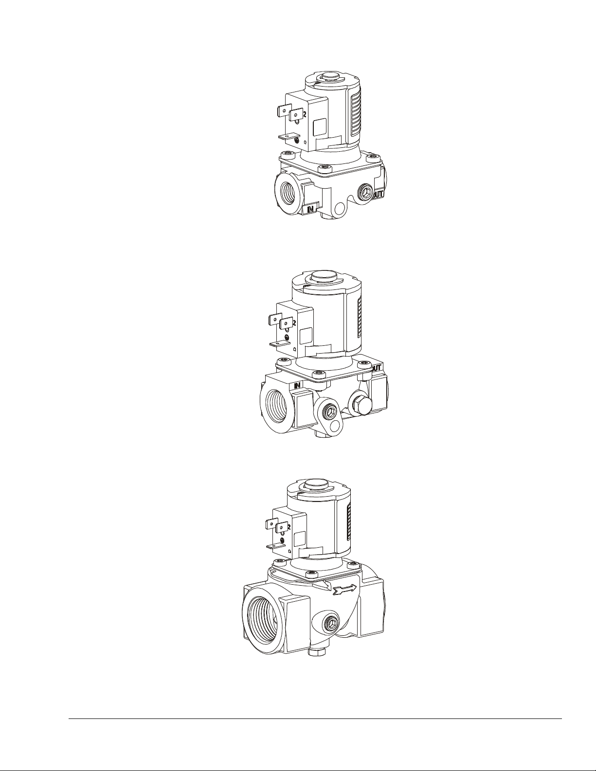
BGA158
BGA171
BGA110
Figure 2: BGA Series Gas Valves
BGA Series Shutoff Gas Valve Installation Instructions 3
Page 4
Wiring
!
WARNING: Risk of Shock.
Disconnect the power supply before making
electrical connections to avoid electrical shock or
equipment damage. Ensure that the operating
voltage is identical to the information on the product
identification label.
!
CAUTION: Equipment Damage Hazard.
For 12 VDC, 25 VDC and 25 VAC applications, the
ground wire must not be connected to prevent
possible grounding of the 12 VDC or 25 VDC power
supply or 25 VAC transformer secondary.
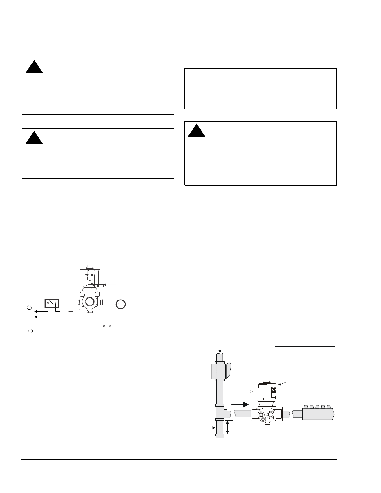
The BGA Series valve is supplied with 3-tab and 2-tab
electrical connections. The tabs of the solenoid coil are
male tag terminals, and electrical connections should
be made using 1/4 in. (6.35 x 0.8 mm) female, fully
insulated push-on terminals. The earth ground terminal
is clearly labeled with the earth ground symbol (see
Figure 3).
Note: Electrical connections can also be made using
pre-wired electrical plugs (DIN 43650 [ISO 4400]).
Non-Polarity Sensitive
Connections
Safety
Control
Ground Tab
24 Volt
Thermostat
Limit(s)
1
L1 (Hot)
L2 (Neu)
1
Power supply provides disconnect
means and overload protection
as required.
25 VDC, 25V, 120V and 240V Only
Figure 3: Electrical Connections
Setup and Adjustments
Checkout
IMPORTANT: All adjustments must be made in
conjunction with the gas appliance and in
accordance with the appliance manufacturer’s
instructions. Only authorized personnel should make
adjustments.
!
WARNING: Risk of Explosion or Fire.
Follow this or an equivalent checkout procedure
after installation. Before leaving the installation,
verify that the gas valve functions properly and that
the system has no gas leaks. Gas leaks can lead to
an explosion or fire, and may result in severe
personal injury or death.
Make sure all components are functioning properly by
performing the following test.
1. Test all joints and connections for leaks with a rich
soap and water solution. If leaks occur, see Step 8
in the Installation section.
2. Close the main manual shutoff valve and wait at
least 5 minutes for unburned gas to escape from
the appliance, and then reopen the shutoff valve.
3. Turn on the main electrical power switch and close
the thermostat contacts. The appliance should
operate in accordance with the manufacturer’s
specified sequence of operation.
4. Turn the thermostat to a low dial setting to open
the contacts. All burner flames should be
extinguished. Repeat Steps 3 and 4 in this section
at least three times.
5. Return the thermostat to a normal setting before
leaving the installation.
Gas Flow
X
indicates possible
locations for other controls.
4 BGA Series Shutoff Gas Valve Installation Instructions
Sediment
Trap
Shutoff Valve
BGA Series
Gas Valve
PRESS
TAP
See Figure 2
OUTIN
X
Direction
of Flow
X
3 in. (76.2 mm)
Minimum
Figure 4: Typical BGA Installation
Burner
Page 5
Repairs and Replacement
Table 1: Replacement Solenoid Coil
(BGA158/BGA171)
Part Number Description
RSDA95A-12
RSDA95A-25
RSDA95A-25V
RSDA95A-120
RSDA95A-240
Table 2: Replacement Solenoid Coil (BGA110)
Part Number Description
RSDA16A-12
RSDA16A-25
RSDA16A-25V
RSDA16A-120
RSDA16A-240
!
CAUTION: Risk of Electric Shock.
Disconnect power supply before making electrical
connections to avoid electric shock.
12 VDC; 2-tab 10.5 VA Coil
25 VAC; 50/60 Hz; 3-tab 10.5 VA Coil
25 VDC; 3-tab 11.5 VA Coil
120 VAC; 50/60 Hz; 3-tab 10.5 VA Coil
240 VAC; 50/60 Hz; 3-tab 10.5 VA Coil
12 VDC; 2-tab 15 VA Coil
25 VAC; 50/60 Hz; 3-tab 15 VA Coil
25 VDC; 3-tab 17 VA Coil
120 VAC; 50/60 Hz; 3-tab 15 VA Coil
240 VAC; 50/60 Hz; 3-tab 15 VA Coil
!
WARNING: Risk of Explosion or Fire.
Shut off the gas supply at the main manual shutoff
valve before installing or servicing the BGA Series.
Failure to shut off the gas supply can result in the
release of gas during installation or servicing, which
can lead to an explosion or fire, and may result in
severe personal injury or death.
!
WARNING: Risk of Explosion, Fire, or
Electric Shock. Label all wires before they are
disconnected when replacing or servicing the BGA
Series. Wiring errors can cause improper or
dangerous operation and may result in an explosion,
fire, or electric shock leading to severe personal
injury or death.
Field repairs must not be made to the BGA Series
valve. Any attempt to repair this assembly voids the
manufacturer’s warranty. For a replacement valve,
contact the original equipment manufacturer or the
nearest BASO Gas Products distributor.
BGA Series Shutoff Gas Valve Installation Instructions 5
Page 6

Technical Specifications
Product
Types of Gas
Maximum Operating
Pressure
Permissible Ambient
(Surface) Temperature
Body Connections
Electrical Ratings
Pressure Connections
Pilot Connections
Operating Time Rating
Valve Timings
Power Ratings
Electrical Connections
Valve Torsion Group
Coil Insulation Class
Packaging
Bulk Pack Quantity
Bulk Pack Weight
Agency Listing
Specification
Standards
Performance specifications are nominal and conform to acceptable industry standards. All agency certification of BASO products is performed
under dry and controlled indoor environmental conditions. Use of BASO products beyond these conditions is not recommended and may void
the warranty. Product must be protected if exposed to water (dripping, spraying, rain, etc.) or other harsh environments. The original
equipment manufacturer or end user is responsible for the correct application of BASO products. Consult BASO Gas Products LLC for
questionable applications. BASO Gas Products LLC shall not be liable for damages or product malfunctions resulting from misapplication or
misuse of its products.
Refer to the BGA158, BGA171, and BGA110 Series Shutoff Gas Valve Product Bulletin (BASO-PB-BGA) for necessary information on
operating and performance specifications for this product.
BGA Series Shutoff Gas Valve
Natural Gas or LP Gas
0.5 psi
-20 to 175ºF (-29 to 79ºC)
1/4, 3/8 or 1/2 cc; 1/8, 1/4, 3/8, 1/2, 3/4 or 1 NPT; 1/8, 1/4, 3/8 or 1/2 BSPP
BGA158/BGA171
12 VDC, 0.875A
25 VAC, 50/60 Hz, 0.42A; 25 VDC, 0.46A
120 VAC, 50/60 Hz, 0.088A
240 VAC, 50/60 Hz, 0.044A
BGA110
12 VDC,1.0A
25 VAC, 50/60 Hz, 0.595A; 25VDC, 0.675A
120 VAC, 50/60 Hz, 0.13A
240 VAC, 50/60 Hz, 0.063A
1/8 NPT left, right, left and right, left/right and bottom, or bottom;
1/8 BSPP (Thread ISO 7-Rp) left, right, left and right, left/right and bottom or bottom; or None
1/8 NPT left, right, or left and right; 1/8 BSPP (Thread ISO 7-Rp) left, right, or left and right; or None
100% Continuous
Closing Time ≤1 Second; Opening Time ≤1 Second; Dead Time <1 Second
BGA158/BGA171 10.5 VA per Coil (except 25 VDC 11.5 VA)
BGA110 15 VA per Coil (except 25 VDC, 17 VA)
3-Tab Solenoid Coil, 2 x 1/4 in. (6.35 mm) + 1/4 in. (6.35 mm) Earth Ground
2-Tab Solenoid Coil, 2 x 1/4 in. (6.35 mm)
Group 2 (EN 161)
Class F
Bulk pack supplied to original equipment manufacturer individual pack optional).
40 or 80 depending on the valve size
BGA158 56 lbs (26 kg), BGA171 48 lbs (22 kg), BGA110 56 lbs (26 kg)
CSA Certificate Number 229521-1656058
UL Recognized File Number MH5939
UL Standard 429
Standards Complying with EMC Directive
Standards Complying with Low Voltage Directive
ANSI Standards Z21.21
Canadian Standards CAN1-6.5
1007 South 12th Street
PO Box 170
Watertown, WI 53094 www.baso.com
1-877-227-6427 (1-877-BASOGAS) Published in U.S.A.
6 BGA Series Shutoff Gas Valve Installation Instructions
 Loading...