

Installation Instructions
Issue Date March 12, 2010
BG1600M51EF-1AA Universal
Intermittent Pilot Ignition Control
Application
The BG1600M51EF-1AA Universal Intermittent Pilot
Ignition Control replaces many existing intermittent
pilot ignition controls made by various
manufacturers. It is a safety control designed for
indirect burner ignition and supervision, for use with
all gases and applicable to gas-fired appliances.
The BG1600M51EF-1AA is a microprocessor based
ignition control. The microprocessor provides reliable
software control of all timings and operates a
diagnostic Light-Emitting Diode (LED). It provides
ignition sequence, flame monitoring, and safety
shutoff for intermittent pilot boilers, furnaces and
other heating appliances. For a complete listing of
specifications, refer to the Technical Specifications
section.
Installation
Parts Included
The BG1600M51EF-1AA is supplied with a parts kit
containing:
• 6 labels for marking wires
• 1/4” terminal for sense wire
• 3 wire nuts
• Rajah adapter described below
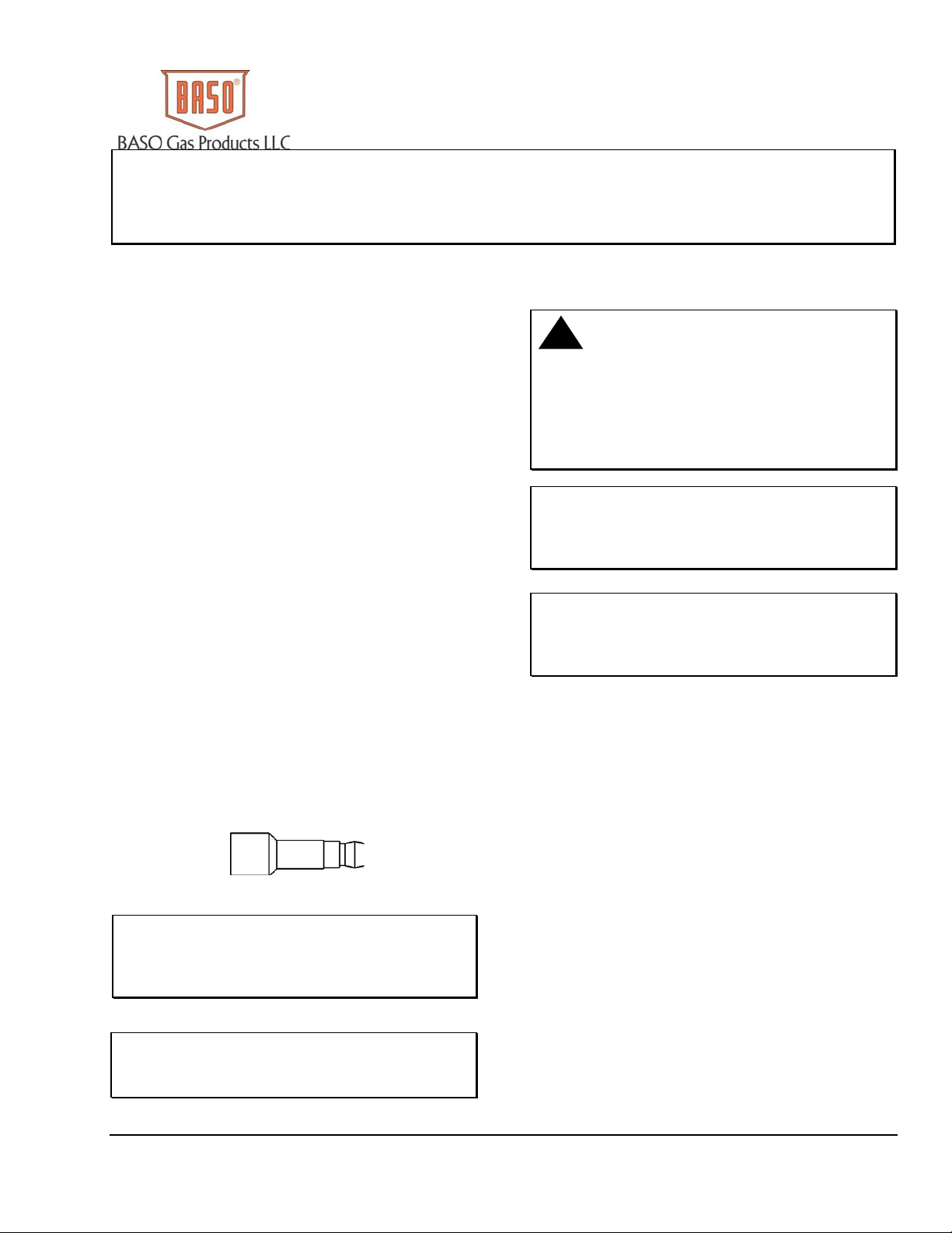
This control uses 1/4” quick connect terminals for
spark connection. If existing cable uses Rajah or
1/4” female spark plug connector, use the adapter
shown in Figure 1.
Figure 1: Rajah Adapter
IMPORTANT: Only qualified personnel
should install or service BASO Gas Products®.
These instructions are a guide for such personnel.
Carefully follow all instructions for the appliance.
IMPORTANT: Make all gas installations in
accordance with applicable local, national, and
regional regulations.
!
WARNING: Risk of Explosion or Fire.
Do not install the control in an area that is exposed
to water (for example, dripping, spraying, rain). Do
not use the control if it has been exposed to water.
Exposure to water may cause malfunction and can
lead to an explosion or fire and may result in
severe personal injury or death.
IMPORTANT: Verify that the control being
replaced is in Table 1 or confirm it is a suitable
replacement using the specifications of the
BG1600M51EF-1AA.
IMPORTANT: This control is approved for
use with noise suppression (resistive) spark wires.
If the application has copper wire, it must be
replaced.
The BG1600M51EF-1AA replaces existing
intermittent pilot ignition controls listed in Table 1 or
controls with the following specifications:
• flame detection using flame rectification
technology (ability of a flame to conduct and
rectify current)
• Single rod (local sense) or dual rod (remote
sense) flame sensing
• 100% shutoff/lockout with 5 minute continuous
retry
• trial times of 25 seconds or longer
• prepurge period 1 second or less
• main burner 400,000 BTU/hr maximum
• pilot burners with flow rates of 1,500 Btu/hr or
less
• with or without automatic vent damper
• must be used with redundant gas valves and not
subjected to temperatures below -40˚F (-40˚C)
or above 170˚F (77˚C)
© 2010 BASO Gas Products. 1
Part No. BASO-INS-BG1600M51EF-1AA, Rev. D www.baso.com

Table 1: Replacement Part Numbers
Part Number Original Manufacturer
Part Number Original Manufacturer
S86A1001 Honeywell
S86A1019 Honeywell
S86A1027 Honeywell
S86A1035 Honeywell
S86B1017 Honeywell
S86B1025 Honeywell
S86C1007 Honeywell
S86C1015 Honeywell
S86C1031 Honeywell
S86C1049 Honeywell
S86C1056 Honeywell
S86D1005 Honeywell
S86D1021 Honeywell
S86E1002 Honeywell
S86E1010 Honeywell
S86E1028 Honeywell
S86G1016 Honeywell
S86G1032 Honeywell
S86G1057 Honeywell
S86G1073 Honeywell
S86H1006 Honeywell
S86H1022 Honeywell
S86H1048 Honeywell
S86H1055 Honeywell
S86H1089 Honeywell
S86H1097 Honeywell
S86H1105 Honeywell
S86H1121 Honeywell
S86H1147 Honeywell
S90A1005 Honeywell
S90B1003 Honeywell
S90B1011 Honeywell
S86E1036 Honeywell
S86E1044 Honeywell
S86E1051 Honeywell
S86E1069 Honeywell
S86E1077 Honeywell
S86E1101 Honeywell
S86E1119 Honeywell
S86E1127 Honeywell
S86F1000 Honeywell
S86F1018 Honeywell
S86F1026 Honeywell
S86F1042 Honeywell
S86F1059 Honeywell
S86F1067 Honeywell
S86F1075 Honeywell
S86F1083 Honeywell
S8600A1001 Honeywell
S8600B1009 Honeywell
S8600B3013 Honeywell
S8600C1015 Honeywell
S8600C3003 Honeywell
S8600F1000 Honeywell
S8600F1034 Honeywell
S8600F1042 Honeywell
S8600H1006 Honeywell
S8600H1022 Honeywell
S8600H1048 Honeywell
S8600H1055 Honeywell
S8600H1071 Honeywell
S8600H1089 Honeywell
S8600H1097 Honeywell
S8600H1105 Honeywell
S86F1091 Honeywell
S86G1008 Honeywell
S8600H3002 Honeywell
S8600M1005 Honeywell
2 BG1600M51EF-1AA Universal Intermittent Pilot Ignition Control Installation Instructions

Part Number Original Manufacturer
S8600M1013 Honeywell
S8600M1021 Honeywell
S8600M1105 Honeywell
S8600M2003 Honeywell
S8600M3001 Honeywell
S8600M4009 Honeywell
S8610A1009 Honeywell
S8610B1007 Honeywell
S8610B1015 Honeywell
S8610C1005 Honeywell
S8610C1013 Honeywell
S8610C3001 Honeywell
S8610F1008 Honeywell
S8610F1016 Honeywell
S8610F1024 Honeywell
Part Number Original Manufacturer
CSA42A-601R Johnson Controls
CSA42A-602R Johnson Controls
CSA42A-603R Johnson Controls
CSA42A-604R Johnson Controls
CSA43A-600R Johnson Controls
CSA44A-600R Johnson Controls
CSA45A-601R Johnson Controls
CSA45A-602R Johnson Controls
CSA46A-600R Johnson Controls
CSA48A-600R Johnson Controls
CSA49A-600R Johnson Controls
CSA49A-605R Johnson Controls
CSA51A-601R Johnson Controls
CSA52A-600R Johnson Controls
G600AX-1,2,3 Johnson Controls
S8610F1032 Honeywell
S8610H1012 Honeywell
S8610H1038 Honeywell
S8610H1046 Honeywell
S8610H1053 Honeywell
S8610H1079 Honeywell
S8610H1095 Honeywell
S8610H3000 Honeywell
S8610H3026 Honeywell
S8610M1003 Honeywell
S8610M1029 Honeywell
S8610M3009 Honeywell
S8610U1003 Honeywell
S8610U1011 Honeywell
S8610U3009 Honeywell
S8620H1002 Honeywell
S8620H1028 Honeywell
CSA35A-617R Johnson Controls
CSA35A-618R Johnson Controls
CSA42A-600R Johnson Controls
G600AY-1 Johnson Controls
G600LX-1,2 Johnson Controls
G600LY-1 Johnson Controls
G600MX-1 Johnson Controls
G600NX-1 Johnson Controls
G600RX-1 Johnson Controls
G60AAA-1 Johnson Controls
G60AAG-1,2,3,4,5,6,7 Johnson Controls
G60CAA-1,3 Johnson Controls
G60CAG-1,2,3,4,5,6,
Johnson Controls
7,8,9
G60CBA-1,2,3 Johnson Controls
G60CBG-1,2,3,4,5,6,7,
Johnson Controls
8,9,10,11,12,13,14,15,
16,17
G60CCA-1 Johnson Controls
G60CCG-1 Johnson Controls
G60CPG-1 Johnson Controls
G60DBG-1 Johnson Controls
G60DCG-1,2,3,4 Johnson Controls
G60GBA-1 Johnson Controls
BG1600M51EF-1AA Universal Intermittent Pilot Ignition Control Installation Instructions 3

Part Number Original Manufacturer
G60GBG-1 Johnson Controls
G60KAG-1 Johnson Controls
G60PAG-1,2,3,4,5,6 Johnson Controls
G60PAJ-1 Johnson Controls
G60PAK-1,2 Johnson Controls
G60PFH-1,2 Johnson Controls
G60PVL-1 Johnson Controls
G60QAG-1,2,3,4 Johnson Controls
G60QAK-1 Johnson Controls
G60QBG-1,2,3,4,5,6,
Johnson Controls
7,8,9
G60QBH-1 Johnson Controls
G60QBK-1,2,3 Johnson Controls
G60QBL-1,2 Johnson Controls
G60QCG-1 Johnson Controls
G60QCJ-1 Johnson Controls
G60QCL-1 Johnson Controls
G60QDG-1 Johnson Controls
G60QFL-1 Johnson Controls
G60QGH-1 Johnson Controls
G60QHL-1,2 Johnson Controls
G60QJL-1 Johnson Controls
G60QLG-1 Johnson Controls
G60QLK-1 Johnson Controls
G60QPG-1 Johnson Controls
G60QPK-1 Johnson Controls
G60QPL-1 Johnson Controls
G60QQJ-1 Johnson Controls
G60QRH-1,2,3 Johnson Controls
G60QRL-1,2,3 Johnson Controls
G60QSL-1 Johnson Controls
G60QTH-1 Johnson Controls
G60QTL-1 Johnson Controls
G60RAG-1 Johnson Controls
G60RBG-1,2,3 Johnson Controls
Part Number Original Manufacturer
G60RBK-1,2 Johnson Controls
G60RCG-1,2 Johnson Controls
G60RCJ-1 Johnson Controls
G60RDG-1 Johnson Controls
G60RDK-1 Johnson Controls
G60RGL-1 Johnson Controls
G60RHL-1 Johnson Controls
G60RHP-1 Johnson Controls
G60RPL-1 Johnson Controls
G60RSL-1 Johnson Controls
G60ZAG-1,2 Johnson Controls
G65BBG-1 through 8 Johnson Controls
G65BBM-1,2,3,4 Johnson Controls
G65BCG-1 Johnson Controls
G65BCM-1 Johnson Controls
G65BFG-1 Johnson Controls
G65BKG-1,2,3 Johnson Controls
G65BKM-1,2,3 Johnson Controls
G65BLG-1,2 Johnson Controls
G65DBM-1,2,3 Johnson Controls
G65DCM-1 Johnson Controls
G65DFM-1 Johnson Controls
G65DKM-1 Johnson Controls
G65DLM-1 Johnson Controls
G66AG-1,2 Johnson Controls
G66BG-1 Johnson Controls
G66MG-1,2 Johnson Controls
G66NG-1 Johnson Controls
G670AW-1, 2 Johnson Controls
G67AG-3,4,7,8,9,10,11 Johnson Controls
G67BG-2,3,4,5 Johnson Controls
G67MG-1,2,3,4 Johnson Controls
G67NG-2,4 Johnson Controls
G770LGA-1,2 Johnson Controls
G770LGC-1,2,3,4 Johnson Controls
4 BG1600M51EF-1AA Universal Intermittent Pilot Ignition Control Installation Instructions

Part Number Original Manufacturer
G770LHA-1,2 Johnson Controls
G770LHC-1 Johnson Controls
G770MGA-1,2,3 Johnson Controls
G770MGC-1,2,3,4,5,6 Johnson Controls
G770MHA-1,2 Johnson Controls
G770MHC-1 Johnson Controls
G770NGA-1 Johnson Controls
G770NGC-4,5,6,7 Johnson Controls
G770NHA-1 Johnson Controls
G770NHC-1 Johnson Controls
G770RGA-1,2,3 Johnson Controls
G770RHA-1,2 Johnson Controls
G775RGA-1 Johnson Controls
G775RHA-1,2 Johnson Controls
G779LHA-1 Johnson Controls
Part Number Original Manufacturer
780-001 Robertshaw
780-002 Robertshaw
780-715 Robertshaw
780-735 Robertshaw
780-736 Robertshaw
780-737 Robertshaw
780-845 Robertshaw
SP715 Robertshaw
SP715A Robertshaw
SP735 Robertshaw
SP735D Robertshaw
SP735L Robertshaw
50D49-350 White-Rodgers
50D49-360 White-Rodgers
IPI-24-00 Camstat
Y79ABC-1 through 7 Johnson Controls
Y79ABD-1,2 Johnson Controls
Y79BBA-1,2 Johnson Controls
05-203025-005 Fenwal
05-203026-005 Fenwal
1003-3 HSC
1003-300 HSC
BG1600M51EF-1AA Universal Intermittent Pilot Ignition Control Installation Instructions 5
Replacing the Existing Ignition Control
!
CAUTION: Risk of Electric Shock.
Disconnect power supply before making electrical
connections to avoid electric shock.
5. Disconnect the vent damper plug/cable (if used)
from the ignition control.
6. Remove the screws holding the ignition control to
the valve (if direct valve-mount model) or remove
the screws holding the control to the appliance
chassis (if foot-mount model).
7. Remove the old ignition control and discard.
!
WARNING: Risk of Explosion or Fire.
Shut off the gas supply at the main manual shutoff
valve before installing or servicing the control.
Failure to shut off the gas supply can result in the
release of gas during installation or servicing, which
can lead to an explosion or fire, and may result in
severe personal injury or death.
!
WARNING: Risk of Explosion, Fire, or
Electric Shock. Label all wires before they are
disconnected when replacing or servicing the
BG1600M51EF-1AA. Wiring errors can cause
improper or dangerous operation and may result in
an explosion, fire, or electric shock leading to severe
personal injury or death.
To remove the existing ignition control:
1. Shut off power to the appliance.
2. Turn off the gas at the main manual shutoff valve
adjacent to the appliance. (If the manual shutoff
valve services more than one appliance, be sure
to light the other pilots before leaving the
installation.)
IMPORTANT: Do not mount the control where
it can be exposed to direct infrared radiation from the
main burner or to temperatures in excess of the
maximum product temperature rating.
8. Mount the new control with #6 sheet metal or
machine screws through the mounting holes in
the enclosure.
9. Refer to the Wiring section for electrical
connections and wiring diagrams. Perform the
Checkout section before leaving the installation.
10. Check all wiring for proper connections and make
sure your system is properly grounded, including
the pilot burner igniter.
Note: The BG1600M51EF-1AA is NOT designed to
replace ignition controls with the following
specifications:
• pilot flame detection by any means other than
flame rectification
• trial for ignition period of less than 25 seconds
• prepurge greater than 4 seconds
• standing pilot applications
3. Label each wire with the correct terminal
designation prior to disconnection, using the
labels provided with the parts kit.
4. Disconnect the wires from the existing control.
6 BG1600M51EF-1AA Universal Intermittent Pilot Ignition Control Installation Instructions

Wiring
!
WARNING: Risk of Explosion or Fire.
Locate all safety, limit, and operating controls in
series with the thermostat terminal (TH) on the
ignition control. Improper installation may cause gas
leaks, which can lead to an explosion or fire and
may result in severe personal injury or death.
Refer to Figure 2 through Figure 5 for wiring diagrams.
All wiring should be in accordance with the National
Electrical Code (NEC) and all other local codes and
regulations.
Check the voltage rating marked on the control and
make sure it is suited to the application. Use a Class 2
transformer capable of providing 24 VAC under
maximum load, including valves. A transformer having
excessive primary impedance due to poor coupling
affects the ignition potential.
The high-voltage spark transformer cable is noise
suppression (resistive) type rated for at least 15kV and
must not be in continuous contact with a metal
surface. Use standoff insulators. Ensure that the flame
sensor wire and high voltage spark transformer cable
are separated from one another by a minimum of
1/4 in. (6.35 mm) and are not wrapped around any
pipe, other wiring, or accessories.
MV/PV
(COM)
MV
2
1
GND
GND
PV
BURNER
345678 109
The control is supplied with a jumper wire between
Sense and Internal terminals and is ready for internal
(one rod) flame sense. With the jumper in, flame is
sensed through the high voltage spark wire. The
jumper must be removed for external (two rod) flame
sense and the sense electrode wired to the Sense
terminal.
Note: A shorting plug that jumpers pins 2 and 3 of the
damper connector is supplied with the control. The
shorting plug must be used if a vent damper is not
used. When a vent damper has been connected and
power turned on, an internal fuse in the control will
blow and the control will only operate with a vent
damper connected. Now you cannot disconnect the
vent damper plug and put back the shorting plug. The
ignition control will not work.
!
WARNING: Risk of Electric Shock.
Before applying power to the control, connect the
high voltage cable to the spark transformer terminal
and spark electrode (pilot burner assembly). Verify
the ground wire is attached to the pilot burner and
the control ground terminal strip. Failure to follow
this procedure can cause electric shock and may
result in severe personal injury or death.
Use jumper
plug s upplied
SENSE
with control.
SPARK
INTERNAL
24V TH
Jumper
Thermostat
4
High
Combination
Gas Valve
56
Pilot
Burner/ignitor
1
Power Supply. Provides disconnect means and overload protection as required.
Maximum cable length 4 8 in c hes (1,220 m m ) . (Resistive wir e r ecommended.)
2
3
For sing le rod applicat ion, leave jum per wire in a s r eceived.
4
Alternate location for limit controller.
5
Controls in 24V circuit must not be in ground leg to transformer.
6
Sensor ro d must be 3/8” ( 9. 53 mm) to 1/2” (12.7 mm) of t he sensor tip should
be in the f la m e for proper s ensing signal.
Chassis or Frame
Ground
5
5
24VAC
Class 2
Transformer
Tem p
Limit
1
L1 (Hot)
L2 (Neu)
23
Figure 2: Wiring for 1 Rod Flame Sense with Vent Damper Jumper Plug
BG1600M51EF-1AA Universal Intermittent Pilot Ignition Control Installation Instructions 7

MV/PV
MV
(COM)
234
1
Use jumper
plug supplied
GND
24V
GND
PV
BURNER
56
with control.
SENSE
TH
8
7
SPARK
INTERNAL
10
9
3
Thermostat
4
Combination
Gas Valve
Pilot
Burner/Ignitor
1
Power Supply. Provides disconnect means and overload prot ection as required.
Maximum cabl e len gt h 4 8 in ches (1,220 mm). (R es is ti ve wir e recommended. )
2
3
For two rod application, remove jumper wire before installation.
4
Alternate locati on for limit controller.
5
Controls in 24V circuit must not be in ground leg to transformer.
6
Maximum ca ble length 48 inches (1,220 mm).
Sensor rod m ust be 3/8” (9.53 mm) to 1/2” (12.7 mm) of the sensor tip should
7
be in the flame for proper sensing sign al .
7
Flame
Sensor
High
Temp
Limit
5
24VAC
Class 2
Transformer
Chassis or Frame
Ground
Discard
Sense Jumper
6
1
L1 (Hot)
L2 (Neu)
2
Figure 3: Wiring for 2 Rod Flame Sense with Vent Damper Jumper Plug
Discard jumper
plug supplied
with the control.
GND 24V TH
678
SENSE
DAMPER
PLUG
SPARK
INTERNAL
10
9
MV
MV/PV
(COM)
2
1
PV
3
GND
BURNER
45
Pilot
Burner/Ignitor
Combination
Gas Valve
Jumper
3
Wiring
Harness
Thermostat
High
4
Temp
1
Limit
6
5
24VAC
Class 2
Transform er
L1 (Hot)
L2 (Neu)
Vent
Damper
2
Chassis or Frame
Ground
1
Power Supply. Provides disconnect means and overload protection as required.
Maximum cable length 48 inches (1,220 mm). (Resistive wire recommended.)
2
3
For sin gle rod application, leave jum per wire in as receiv ed .
4
Alternate location for limit controller.
5
Controls in 24V circuit must not be in ground leg to transformer.
6
Sensor rod must be 3/8” ( 9. 53 m m) to 1/ 2” ( 12 .7 mm ) of the sensor tip should
be in the flame for pro per se nsing signal.
Figure 4: Wiring for 1 Rod Flame Sense with Vent Damper
8 BG1600M51EF-1AA Universal Intermittent Pilot Ignition Control Installation Instructions

Discard jumper
plug supplied
MV/PV
(COM)
MV
2
1
PV
3
GND
BURNER
45
GND
with the control.
24V
TH SENSE
67
INTERNAL
DAMPER
PLUG
89
SPARK
10
1
Power Supply. Provides d isconnect means and overl oad protection as required.
Maximum cable length 48 inches (1,2 20 mm). (Resistive wire recom mended.)
2
3
For two ro d application s r e m ove jumper wi re before insta ll at i on.
4
Alternate location for limit controller.
5
Controls in 24V circuit must not be in ground leg to transformer.
6
Maximum cable length 4 8 in ches (1,220 mm).
7
Sensor r od must be 3/8” ( 9.53 mm) to 1/2” ( 12.7 mm) of the sensor tip should
be in the f la m e f or pr oper sensin g signal.
Figure 5: Wiring for 2 Rod Flame Sense with Vent Damper
Setup and Adjustments
Pilot
Burner/Ignitor
Combination
Gas Valve
7
Flame
Sensor
Thermostat
4
5
24VAC
Class 2
Transformer
Chassi s or Frame
Ground
High
Temp
Limit
6
L1 (Hot)
L2 (Neu)
Wiring
Harness
1
Discard Sense
Vent
Damper
3
Jumper
2
Instructions for Specific Models
Follow the instructions below for replacement of
specific control models.
Replacing Honeywell® S8610U1003 and S86xx
Controls
The BG1600M51EF-1AA control has 1/4 inch
terminals whose general locations and labels match
the S8610U1003 and other S86xx controls. If a two
rod flame sense is used, the 3/16 inch terminal on the
flame sense wire must be replaced with the 1/4 inch
terminal provided in the parts kit. Verify that the spark
wire is noise suppression (resistive) type and replace if
necessary.
Replacing Johnson Controls® G600AX-1 and
G600LX-1
The G600AX-1 and G600LX-1 use the same terminal
numbers as the G77x without text labels. Use the
Rajah spark adapter included in the parts kit. Verify
that the spark wire is noise suppression (resistive) type
and replace if necessary.
Table 2: Replacing Johnson Controls® G779LHA-1
and G77x
Wire Function G77x BG1600M
Main Valve 3 MV 1 MV
Valve Common Ground Plate 2 MV/PV
Pilot Valve 1 PV 3 PV
Pilot Burner Ground Ground Plate
4 GND
(BURNER)
Power Supply Ground Ground Plate 5 GND
24VAC Power
(if damper is used)
6 24V 6 24V
Thermostat 2 THS 7 TH
Sense Electrode
(if two rod sense)
4 SENSE 8 SENSE
If the G77x uses a spike type high voltage connector.
It will be necessary to replace the spark cable
assembly.
BG1600M51EF-1AA Universal Intermittent Pilot Ignition Control Installation Instructions 9

Table 3: Replacing Robertshaw® 780-845
Wire Function 780-845 BG1600M
Main Valve MV 1 MV
Valve Common PV-MV 2 MV/PV
Pilot Valve PV 3 PV
Pilot Burner Ground GND
Power Supply Ground TR 5 GND
Thermostat TH 7 TH
Sense Electrode
(if two rod sense)
Note: Verify that the spark wire is noise suppression
(resistive) type and replace if necessary.
SENSE 8 SENSE
4 GND
(BURNER)
8. Check for gas leaks on all pipe joints downstream
of the gas valve with a soap solution.
9. Turn the thermostat down for at least 30 seconds
and then back up again. Verify successful ignition
at least five times.
10. Return the thermostat to a normal temperature
setting before leaving the installation.
!
WARNING:
The control module can not be serviced by user. If
any faults are detected, the control module must be
replaced. If control module has been opened or any
attempts to repair are done, the warranty is void.
Checkout
!
WARNING: Risk of Explosion or Fire.
Verify that there are no gas leaks by testing with
appropriate equipment. Never use a match or lighter
to test for the presence of gas. Failure to test
properly can lead to an explosion or fire and may
result in severe personal injury or death.
Make sure all components function properly by
performing the following test.
1. Before starting the appliance, perform a safety
inspection of piping, burners and venting. Check
for water leaks, etc. Check all wiring for proper
connections. Be sure the system is properly
grounded, including ground connection to the
pilot burner.
2. With the gas and thermostat off, turn on power to
the appliance.
3. Turn the thermostat to a high setting and verify
that the control goes through the operating
sequence to a shutoff condition.
Note: The burner does not light because the
gas is off.
4. Turn off the thermostat.
5. Turn on the gas and purge gas lines of all air.
6. Check for gas leaks on all pipe joints upstream of
the gas valve with a soap solution.
7. Turn the thermostat to the highest setting and
verify successful ignition and a normal run
condition for at least 5 minutes. If the appliance
fails to run, see the Troubleshooting section.
Operation
Operating Mode Definitions
The following definitions describe the
BG1600M51EF-1AA operating conditions.
• Prepurge: Initial time delay between thermostat
contact closure and activation of the spark circuit
and pilot valve.
• Trial for Ignition: Total time the pilot valve is
energized and spark/sense sequence is activated
in an attempt to light the pilot. The control attempts
to prove flame within the trial-for-ignition time.
• 100% Shutoff: If the control does not prove the
presence of pilot burner flame within the trial for
ignition, the spark circuit and pilot valve are
de-energized.
• Recycle: If 100% shutoff occurs, the control
delays 5 minutes (recycle delay period) and
begins another trial for ignition.
• Run: Main valve is energized and spark turns off
after pilot flame is proven. The main valve remains
energized until the thermostat is satisfied.
• Flameout: Loss of proven flame. Should a
flameout occur, the main valve de-energizes and
spark recurs within 2.0 seconds.
• Lockout: An internal or external fault has caused
the control to de-energize the spark circuit and
valve relays. The thermostat contacts must be
opened for 30 seconds and then closed to begin
another trial for ignition.
• Inter-Purge: Period between trials for ignition
when both the gas valve and spark are
de-activated to allow unburned gas to escape
before the next trial.
10 BG1600M51EF-1AA Universal Intermittent Pilot Ignition Control Installation Instructions

Sequence of Operation
The heating cycle starts when a call for heat from the
thermostat supplies 24VAC to the TH terminal. The
automatic vent damper (if used) is energized and
when fully open, turns on the power to the ignition
control. After a 1 second maximum diagnostic period,
the spark will start and the pilot valve will turn on,
starting the trial for ignition period.
During the trial for ignition period, the control sparks
for 4 seconds while rapidly flashing LED. It then turns
off the spark and LED for 1 second while checking
pilot flame sense. This cycle will repeat until pilot flame
is detected or trial time is over.
When pilot flame is detected, the spark will stop, main
valve will turn on and the LED will stay on
continuously. The control will remain in this state until
the pilot flame is lost or the call for heat ends. If pilot
flame is lost, LED, main and pilot valves are turned off
for 0.5 seconds and a new trial for ignition sequence
will start.
If pilot flame is not detected during the trial for ignition
period, the pilot valve will be shut off. The control will
wait for 5 minutes while blinking the LED at the end of
each 15 seconds. When the 5 minute period is over a
new trial for ignition sequence will start. The control
will recycle continuously until flame is proven or call for
heat ends.
Table 4: LED Indications During Normal Operation
Flash Code Flash Code Indication
Troubleshooting
If the system does not function properly, determine the
cause using the procedures in this section.
Before proceeding with troubleshooting the system,
check the following.
Preliminary Checks
Are all mechanical and electrical connections
tight?
Is the system wired and ground correctly?
Is gas inlet pressure per manufacturer’s
specifications?
Is the system powered?
Is the thermostat calling for heat?
!
WARNING: Risk of Personal Injury.
Do not place face, hands, or other parts of the body
in or near the burner area when the LED is flashing
(recycle mode). When the LED is flashing, the
control may at any time (while in the recycle mode)
re-energize the burner control system and ignite the
burner which may result in electric shock from
contact with the electrode or severe burn injury from
firing of the burner.
Steady On Flame detected, main burner on
.1 Second On
.1 Second Off
.5 Second
Trial time spark on trying to light
pilot burner
In 5 minute recycle period
Every 15 Seconds
BG1600M51EF-1AA Universal Intermittent Pilot Ignition Control Installation Instructions 11

LED Error Indications
If the control module’s internal diagnostics detect a fault it
will go into lockout. Spark and both valves will be turned
off. The LED will flash an error code .25 seconds on and
.25 seconds off for each count of the error code with
1 second off between codes. The control will remain in
this condition until power is removed by turning off the call
Table 5: LED Error Indications
Flash
Code
Flash Code
Description
for heat. A flashing LED error code indicates either a
problem with wiring, or a component not working, or the
control module is faulty. Try to cycle the control again. If
the error repeats then see Table 5 for troubleshooting.
Troubleshooting Guide
No
LED
“ON”
1
2
3
4
5
6 to 9
No Power
No flame in
trial time
Flame sense
circuit error
PV
(Pilot Valve)
circuit error
MV
(Main Valve)
circuit error
Internal
Control error
Internal
Control error
1. With the MOLEX Vent Damper jumper plug installed, check for 24 volts on terminal 7
(TH) and terminal 5 (GND). If using a Vent Damper, make sure it is connected and
working and check for 24 volts on terminals 6 (24V) and 7 (TH) to terminal 5 (GND).
2. Check for 24 volts on the secondary coil of the incoming transformer.
1. Check if the gas is turned “ON”.
2. With the MOLEX Vent Damper jumper plug installed, check for 24 volts on terminal 7
(TH) and terminal 5 (GND). If using a Vent Damper, make sure it is connected and
working and check for 24 volts on terminals 6 (24V) and 7 (TH) to terminal 5 (GND).
3. If no spark, check spark wire and connection to terminal 10 (SPARK) and spark ground
to terminal 4 (GND BURNER).
4. Check if PV is wired to terminal 3 (PV) and common is wired to terminal 2
(MV/PV COM).
5. Check for 24 volts at the PV coil.
1. Check Flame Sensor tip is in the flame. For proper sensing the rod tip must be
3/8”(10mm) to 1/2”(13 mm) in the flame.
2. Check Flame Sensor circuits;
2.1. For 1 Rod Flame Sense circuit, check Spark/Flame Sensor is wired to terminal 10
(SPARK) and terminal 4 (GND BURNER). And check Jumper wire is installed between
terminal 8 (SENSE) and terminal 9 INTERN).
2.2. For 2 Rod Flame Sense circuit, check Flame Sensor is wired to terminal 8 (SENSE) and
terminal 4 (GND BURNER).
1. Check for 24 volts on terminal 3 (PV) and terminal 2 (MV/PV COM).
2. Check if PV is wired to terminal 3 (PV) and common is wired to terminal 2
(MV/PV COM).
3. Check for 24 volts at the PV coil.
1. Check for 24 volts on terminal 1 (MV) and terminal 2 (MV/PV COM).
2. Check MV is wired to terminal 1 (MV) and common is wired to terminal 2 (MV/PV COM).
3. Check for 24 volts at the MV coil.
1. Review all ground connections.
2. Check if using fiber core resistive wire for Spark Wire.
1. Software error – Restart control module.
NOTE: If the Troubleshooting Guide has been used for an error code being flashed, and the Control Module is not
working, then the Control Module maybe faulty. Replace the Control Module.
12 BG1600M51EF-1AA Universal Intermittent Pilot Ignition Control Installation Instructions

Idle State
Call for heat
from the thermostat
If damper connected
wait for it to open
Note:
If the thermostat opens,
the control will turn off valves
and returns to the idle state.
FLAME ON MONITOR LOOP
Wait 0.1 se cond
checking m emory and
relay driver circuits
OK
One second for
diagnost ic routines
If pre-pu r ge wait
flashing LED once a
second u nt il over
Turn on spark and
pilot gas valve
start trial timer
Spark on 4 seconds
blinking LE D rapidly
spark off 1 second
Flame
on?
No
TRIAL
TIME
LOOP
Trial
No
over?
TRIAL
TIME
OVER
Yes
POWER TO CONTROL
Yes
Wait 0.5 se cond
No
Tur n on main
gas valve and LED
Flame
on?
Yes
0.7 second?
Turn pilot and main
gas valves off
wait 0.7 second
inter-purge blinking
LED once a second
RE-LIGHT
Flame
Flame off
Yes
on?
No
No
FLAME LOST, TURN
Yes
OFF VALVES AND
TRY TO RE-LIGHT
Note:
Lock out on t imeout or fault det ect ed,
turn off r elays and spa r k loop bli nking
error code until power off.
Error Codes
No flame in trial time.
Flame sense stuck on.
Pilot relay driver fault.
Main relay driver fault.
Processor errors.
1 Blink
2 Blinks
3 Blinks
4 Blinks
5 to 9 Blinks
Turn pilot gas
valve off
Retry
option?
Yes
Wait 5 m in utes,
blink LED every 15 secon ds
BG1600M51EF-1AA Universal Intermittent Pilot Ignition Control Installation Instructions 13
Lockout
RESTART
Figure 6: Sequence of Operation

Turn on power
and gas.
Close thermostat
contacts.
Module LED
did not light and
no spark?
No
Module LED
blinks slowly?
No
Module LED
blinks rapidly but
no spark?
No
Pilot flame
does not
light?
No
Yes
Yes
Yes
Yes
Diagnostic error
see next page.
Replace mod ule.
Spark w ire
and electrode
OK?
No
Replace spark wir e
or electrode.
24V between
PV and GND
terminals?
No
Replace
module.
Yes
Replace
module.
Yes
Gas at pilot
Adjust or replace spark
electro de and /or pilot
24V between
TH and GND
terminals?
Connect pin 2-3
shor ting plug to
burner?
Yes
burner.
Yes
Damper
used?
No
Shorting
plug in?
No
damper.
No
No
Check transformer,
thermostat and wiring.
Repair or replace as needed.
Yes
24V between
damper pin 2 & 4?
Yes
Yes
Check orfice and tubing are clear.
Replace
module.
Check shutoff valves are on.
Check wiring to pilot valve.
If all OK replace pilot valve.
No
Check and repair
damper, and/or
damper wiri ng.
Pilot lights
but keeps
sparking?
No
Pilot is lit
continued
on next page
Pilot flame in contact
with spark or sense
electrode?
Yes
Two rod
flame sense?
Yes
Check wiring electrode
to SENSE terminal.
If OK replace module.
NoYes
No
Check burner orifice.
Adjust pilot flame size or
electro de position.
Replace
module.
Figure 7: Troubleshooting Flow Chart (1 of 2)
14 BG1600M51EF-1AA Universal Intermittent Pilot Ignition Control Installation Instructions

Continued
from p revio us page
Pilot is lit
Main burner
failed to turn
on?
No
After main is
lit, do valves turn off
and star t new
cycle?
No
Control is
operating
normally.
Yes
Yes
Yes
24V between
MV and MV/PV
terminals?
No
Replace
module.
Pilot flame in
contact with spark or
sense el ectrode?
Yes
Two rod
flame sense ?
Yes
Yes
No
No
Gas at main
burner?
Adjust pilot flame size
and posit ion, or replace
pilot burn er or m ain burner.
Adjust pilot flame size or
Replace
module.
No
Yes
electrode position.
Check that shutoff valves are on.
Check wiring to main valve.
Check tubing is clear.
If all OK replace main valve.
Check wiring electrode
to SENSE terminal.
If OK replace module.
Figure 8: Troubleshooting Flow Chart (2 of 2)
BG1600M51EF-1AA Universal Intermittent Pilot Ignition Control Installation Instructions 15

Maintenance Requirements in Severe
Environments
Regular preventive maintenance is important in any
application, but especially so in commercial cooking,
agricultural, and industrial applications because:
• In many such applications, particularly
commercial cooking, the equipment operates
100,000 to 200,000 cycles per year. Such heavy
cycling can wear out the gas control in one to
two years. A normal forced air furnace, for which
the controls were originally intended, typically
operates less than 20,000 cycles per year.
• Exposure to water, dirt, chemicals, and heat can
damage the ignition control module or the gas
control and shut down the control system. A
NEMA 4 enclosure can reduce exposure to
environmental contaminants.
!
WARNING: Risk of Explosion or Fire. Do
not attempt to take the ignition control module apart
or to clean it. Improper reassembly and cleaning
may cause unreliable operation, which can lead to
an explosion or fire, and may result in severe injury,
property damage or death.
Maintenance frequency must be determined
individually for each application. Some considerations
are:
• Cycling Frequency – Appliances that may cycle
more than 20,000 times annually should be
checked monthly.
• Intermittent Use – Appliances that are used
seasonally should be checked before shutdown
and again before the next use.
• Consequence of Unexpected Shutdown –
Where the cost of an unexpected shutdown
would be high, the system should be checked
more often.
Repairs and Replacement
!
CAUTION: Risk of Electric Shock.
Disconnect power supply before making electrical
connections to avoid electric shock.
!
WARNING: Risk of Explosion or Fire.
Shut off the gas supply at the main manual shutoff
valve before installing or servicing the control.
Failure to shut off the gas supply can result in the
release of gas during installation or servicing, which
can lead to an explosion or fire, and may result in
severe injury or death.
!
WARNING: Risk of Explosion, Fire, or
Electric Shock. Label all wires before they are
disconnected when replacing or servicing the
BG1600M51EF-1AA. Wiring errors can cause
improper or dangerous operation and may result in
an explosion, fire, or electric shock leading to severe
personal injury or death.
Field repairs must not be made to the
BG1600M51EF-1AA control. Any attempt to repair this
assembly voids the manufacturer’s warranty. For a
replacement control, contact the original equipment
manufacturer or the nearest BASO Gas Products
distributor.
All other accessories, such as flame sensors,
electrode assemblies, pilot assemblies, and leads can
be obtained through the original equipment
manufacturer or a BASO Gas Products distributor.
• Dust, Wet, or Corrosive Environment – Since
these environments can cause the controls to
deteriorate more rapidly, the system should be
checked more often.
16 BG1600M51EF-1AA Universal Intermittent Pilot Ignition Control Installation Instructions

Ignition Control Accessories
Table 6: Ignition Control Accessories
Part Number Description
RAA1600A-601D Rajah to 1/4” Spade Adapter (box of 50)
RAA1600A-601H Rajah to 1/4” Spade Adapter (bag of 10)
WHA40A-600D 18” Resistive Wire Harness with (2) 1/4” Terminals (box of 25)
WHA40A-600H 18” Resistive Wire Harness with (2) 1/4” Terminals (bag of 1)
WHA40A-601D 18” Resistive Wire Harness with (1) 1/4” Terminal and 1 Rajah Terminal (box of 25)
WHA40A-601H 18” Resistive Wire Harness with (1) 1/4” Terminal and 1 Rajah Terminal (bag of 1)
WHA40A-602D 24” Resistive Wire Harness with (2) 1/4” Terminals (box of 25)
WHA40A-602H 24” Resistive Wire Harness with (2) 1/4” Terminals (bag of 1)
WHA40A-603D 24” Resistive Wire Harness with (1) 1/4” Terminal and 1 Rajah Terminal (box of 25)
WHA40A-603H 24” Resistive Wire Harness with (1) 1/4” Terminal and 1 Rajah Terminal (bag of 1)
WHA40A-604D 36” Resistive Wire Harness with (2) 1/4” Terminals (box of 25)
WHA40A-604H 36” Resistive Wire Harness with (2) 1/4” Terminals (bag of 1)
WHA40A-605D 36” Resistive Wire Harness with (1) 1/4” Terminal and 1 Rajah Terminal (box of 25)
WHA40A-605H 36” Resistive Wire Harness with (1) 1/4” Terminal and 1 Rajah Terminal (bag of 1)
WHA40A-606D 48” Resistive Wire Harness with (2) 1/4” Terminals (box of 25)
WHA40A-606H 48” Resistive Wire Harness with (2) 1/4” Terminals (bag of 1)
WHA40A-607D 48” Resistive Wire Harness with (1) 1/4” Terminal and 1 Rajah Terminal (box of 25)
WHA40A-607H 48” Resistive Wire Harness with (1) 1/4” Terminal and 1 Rajah Terminal (bag of 1)
Cut out and leave near control.
.1 Second On, .1 Second Off Trial time spark on trying to light pilot burner
.5 Second Every 15 Seconds In 5 minute recycle period
LED Error Indications .25 Second On and .25 Second Off
LED Indications During Normal Operation
Steady On Flame detected, main burner on
1 No flame in trial time
2 Flame sense circuit error
3 Pilot valve circuit error
4 Main valve circuit error
5 to 9 Internal control error
BG1600M51EF-1AA Universal Intermittent Pilot Ignition Control Installation Instructions 17

Notes
18 BG1600M51EF-1AA Universal Intermittent Pilot Ignition Control Installation Instructions

Technical Specification
Product
Ignition Type
Ignition Source
High Voltage Cable
Maximum Length
Flame Sense Cable
Maximum Length
Flame Detection Means
Flame Detection Type
Minimum Flame Current
Flame Failure Response
Time
Maximum Spark Gap
Number of Trials Before
100% Shutoff
Trial-for-Ignition Time
Prepurge Time
Automatic Recycle Delay
Period
Power Requirements
Contact Rating
Wiring Connections
Maximum Firing Rate
Ambient Operating and
Storage Temperature
Humidity
Type of Gas
Packaging
Bulk Pack Quantity
Pack Weight
Agency Listing
Specifications Standards
The performance specifications are nominal and conform to acceptable industry standards. All agency certification of BASO products is
performed under dry and controlled indoor environmental conditions. Use of BASO products beyond these conditions is not recommended and
may void the warranty. If the product is exposed to water (dripping, spraying, rain, etc.) or other harsh environments, it must be protected. The
original equipment manufacturer or end user is responsible for the correct application of BASO products. For questionable applications, please
consult BASO Gas Products LLC. BASO Gas Products LLC shall not be liable for damages or product malfunctions resulting from
misapplication or misuse of its products.
BG1600M51EF-1AA Universal Intermittent Pilot Ignition Control
Indirect
High voltage spark, capacitive discharge
48 in. (1,220 mm) (Resistive wire recommended, rated for at least 15Kv.)
48 in. (1,220 mm)
Flame Rectification
Local or Remote
0.15 microamperes
2 seconds maximum
0.2 in. (5.1 mm)
One
25 seconds then 100% shutoff (pilot and main gas)
1 second maximum
5 minutes
Control:
Operation Current:
Main Valve:
Pilot Valve:
24 VAC (+/- 20%), 50/60 Hz
0.2 A nominal + valves
2 A maximum
1 A maximum
1/4 in. (6.35 mm) male spade
400,000 Btu/hr (117 kW)
-40 to 170°F (-40 to 77°C)
95% RH noncondensing
Natural, Liquefied Petroleum (LP), Manufactured, Mixed or LP Gas-Air Mixture
Bulk pack supplied to original equipment manufacturer (individual pack [-1AAC] or
individual overpack [-1AAE, 20 per box] optional)
25
Bulk pack (-1AAD) 14 lb (6.36 kg)
Individual pack (-1AAC) 1 lb (.454 kg)
Individual overpack (-1AAE) 18 lb (8.17 kg)
CSA Certificate Number 246569-2161442
ANSI Standard Z21.20
CAN/CSA-C22.2 No. 199
1007 South 12th Street
PO Box 170
Watertown, WI 53094 Published in U.S.A.
1-877-227-6427 www.baso.com
BG1600M51EF-1AA Universal Intermittent Pilot Ignition Control Installation Instructions 19
 Loading...