

Installation Instructions
Issue Date October 19, 2010
BG1600M Intermittent Pilot Ignition Control
with Rollout Switch
Application
The BG1600M Intermittent Pilot Ignition Control is a
safety control designed for indirect burner ignition and
supervision, for use with all gases and applicable to
gas-fired appliances.
The BG1600M is a microprocessor based ignition
control. The microprocessor provides reliable software
control of all timings and operates a diagnostic
Light-Emitting Diode (LED). It provides ignition
sequence, flame monitoring, and safety shutoff for
intermittent pilot boilers, furnaces and other heating
appliances. For a complete listing of specifications,
refer to the Technical Specifications section.
Instructions for installing the pilot burner/igniter-sensor
are typically provided by the appliance manufacturer. It
is important to follow those instructions. If such
information is not included, refer to the Mounting
section.
Mounting
!
CAUTION: Risk of Electric Shock.
Disconnect power supply before making electrical
connections to avoid electric shock.
Installation
IMPORTANT: Only qualified personnel should
install or service BASO Gas Products®. These
instructions are a guide for such personnel. Carefully
follow all instructions for the appliance.
IMPORTANT: Make all gas installations in
accordance with applicable local, national, and
regional regulations.
!
WARNING: Risk of Explosion or Fire.
Do not install the control in an area that is exposed
to water (for example, dripping, spraying, rain). Do
not use the control if it has been exposed to water.
Exposure to water may cause malfunction and can
lead to an explosion or fire and may result in severe
personal injury or death.
!
WARNING: Risk of Explosion or Fire.
Shut off the gas supply at the main manual shutoff
valve before installing or servicing the control.
Failure to shut off the gas supply can result in the
release of gas during installation or servicing, which
can lead to an explosion or fire, and may result in
severe personal injury or death.
IMPORTANT: Do not mount the control where
it can be exposed to direct infrared radiation from the
main burner or to temperatures in excess of the
maximum product temperature rating.
IMPORTANT: This control is approved for use
with noise suppression (resistive) spark wires. If the
application has copper wire, it must be replaced.
© 2010 BASO Gas Products. 1
Part No. BASO-INS-BG1600MRO, Rev. - www.baso.com

Location Considerations
Choose a location that provides the shortest, direct
cable route to the spark electrode, pilot burner/ignitersensor assembly. Easy access to the terminals is
desired for wiring and servicing. The control may be
mounted in any position. Mount the control on a
grounded metal surface with #6 sheet metal or
machine screws through the mounting holes provided
in the enclosure.
The pilot burner/igniter-sensor must be securely
mounted to the main burner to ensure that the pilot
burner flame remains properly positioned with respect
to the main burner flame. The pilot burner must be
located such that the flame receives an ample supply
of air, free from the products of combustion. The flame
must not be exposed to draft conditions, the full force
of main burner ignition, or falling scale, which could
otherwise impede ignition of main burner flame.
Securely mount the pilot burner/igniter-sensor to the
main burner with metal screws at a distance
approximately 3/8 in (9.52 mm) above and 1/4 in. (6.35
mm) away from the center of the nearest main burner
port. Ensure that the main burner flames do not
impinge on any part of the pilot burner.
Wiring
The high-voltage spark transformer cable is noise
suppression (resistive) type rated for at least 15kV and
must not be in continuous contact with a metal
surface. Use standoff insulators. Ensure that the flame
sensor wire and high voltage spark transformer cable
are separated from one another by a minimum of
1/4 in. (6.35 mm) and are not wrapped around any
pipe, other wiring, or accessories.
!
WARNING: Risk of Electric Shock.
Before applying power to the control, connect the
high voltage cable to the spark transformer terminal
and spark electrode (pilot burner assembly). Verify
the ground wire is attached to the pilot burner and
the control ground terminal strip. Failure to follow
this procedure can cause electric shock and may
result in severe personal injury or death.
The BG1600M replaces existing intermittent pilot
ignition controls with the following specifications:
• flame detection using flame rectification
technology (ability of a flame to conduct and
rectify current)
• 1 trial for ignition
!
WARNING: Risk of Explosion or Fire.
Locate all safety, limit, and operating controls in
series with the thermostat terminal (TH) on the
ignition control. Improper installation may cause gas
leaks, which can lead to an explosion or fire and
may result in severe personal injury or death.
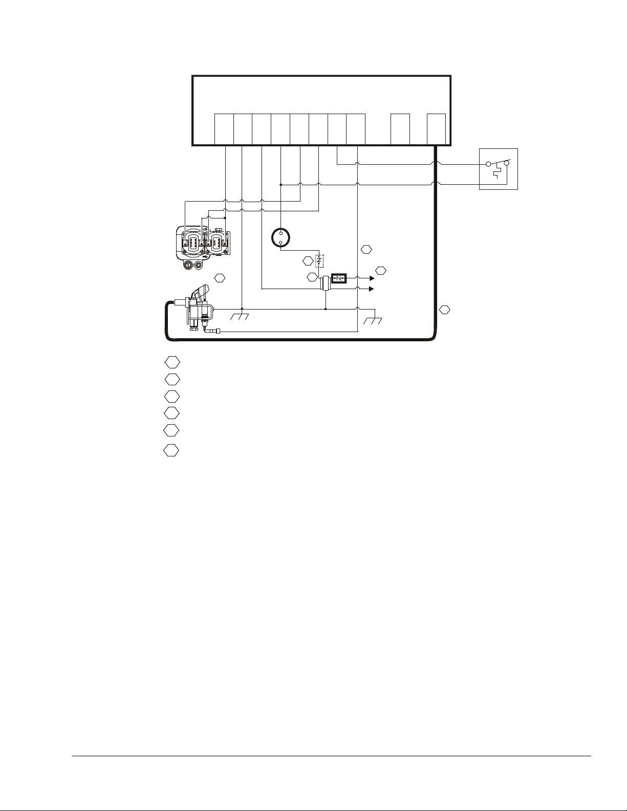
Refer to Figure 1 for wiring diagrams. All wiring should
be in accordance with the National Electrical Code
(NEC) and all other local codes and regulations.
Check the voltage rating marked on the control and
make sure it is suited to the application. Use a Class 2
transformer capable of providing 24 VAC under
maximum load, including valves. A transformer having
excessive primary impedance due to poor coupling
affects the ignition potential.
• dual rod (remote sense) flame sensing
• 100% shutoff/lockout with none or 5 minutes
continuous retry
• trial time for ignition is 85 seconds
• prepurge period of none or 15 seconds
• interpurge period of 15 seconds
• main burner 400,000 Btu/hr maximum
• pilot burners with flow rates of 1,500 Btu/hr or
less
• must be used with redundant gas valves and
not subjected to temperatures below
-40˚F (-40˚C) or above 170˚F (77˚C)
2 BG1600M Intermittent Pilot Ignition Control with Rollout Switch Installation Instructions
Combination
Gas Valve
Pilot
Burner/Ignitor
PV
MV
6
Flame
Sensor
GND
(MV/PV)
GND
GND
(24V)
(BURNER)
234
24V/TH
Transformer
MV
PV
56
Thermostat
3
4
24VAC
Class 2
Chassis or Frame
Ground
71
High
Temp
Limit
SENSE
R.O. SW
8
INTERN
9
SPARK
10
Rollout
Switch
5
1
L1 (Hot)
L2 (Neu)
2
1
Power Supply. Provides disconnect means and overload protection as required.
2
Maximum cable len gt h 48 inches (1, 220 mm). (R esistive wi re r ecommended.)
3
Alternate location for limit controller.
4
Controls in 24V circuit must not be in ground leg to transformer.
5
Maximum cable length 48 inches (1,220 mm).
Sensor rod must b e 3/ 8” ( 9. 53 mm) to 1/ 2” ( 12.7 mm) of t he sensor t ip should
6
be in the fla m e f or pr oper sens in g signal.
Figure 1: Wiring for 2 Rod Flame Sense with Rollout Switch
Rollout Switch Function
The rollout switch is wired to the BG1600M ignition control
at Terminal 7 (R.O. SW) and Terminal 4 (24V/TH) (see
Figure 1). The rollout switch (a normally closed set of
contacts) is positioned to detect flames rolling out of the
combustion chamber. If rollout occurs, the switch contacts
open and the BG1600M immediately goes into a lockout
condition, closing the main and pilot valves so that the
system is not allowed to function.
The thermostat contacts must be opened for 30 seconds,
then closed to escape the lockout condition. When the
rollout switch contacts have returned to the closed
position, the BG1600M will start its operating sequence
when the thermostat contacts close.
BG1600M Intermittent Pilot Ignition Control with Rollout Switch Installation Instructions 3
Typical Wiring Chart
JCI (Johnson Controls) To BASO Intermittent Pilot Ignition (IPI) Control
G77xRJx Series to BG1600M0 Series with Remote Sense
with Rollout Switch
and R.O. Switch
JCI (IPI)
G770 RJA-1C BG1600M00ER-1BD
TO
TO
BASO (IPI)
G775 RJD-1
G775 RJD-13C
G775 RJD-14
TO
BG1600M01CR-1BD
G775 RJD-15
G775 RJD-2
Label
(REF)
GND
(VALVE)
GND
(BURNER)
GND
(24V)
THS 2 Connect To 4 24V / TH
TB
#
5/Chassis
(frame)
5/Chassis
(frame)
5/Chassis
(frame)
TB
SPADE
Connect To 1
Connect To 2
Connect To 3
TB
TB
#
Label
GND
(MV/PV)
GND
(BURNER)
GND
(24V)
PV 1 Connect To 5 PV
MV 3 Connect To 6 MV
R.O. SWH R1 Connect To 7 R.O. SW
SENSE 4 Connect To 8 SENSE
NC none
NC none 9 INTERN
SPARK Rajah Connect To 10 SPARK
NOTE: NC means No Connection
4 BG1600M Intermittent Pilot Ignition Control with Rollout Switch Installation Instructions
Setup and Adjustments
Checkout
!
WARNING: Risk of Explosion or Fire. Verify
that there are no gas leaks by testing with appropriate
equipment. Never use a match or lighter to test for the
presence of gas. Failure to test properly can lead to an
explosion or fire and may result in severe personal injury
or death.
Make sure all components function properly by performing
the following test.
1. Before starting the appliance, perform a safety
inspection of piping, burners and venting. Check for
water leaks, etc. Check all wiring for proper
connections. Be sure the system is properly
grounded, including ground connection to the pilot
burner.
2. With the gas and thermostat off, turn on power to the
appliance.
3. Turn the thermostat to a high setting and verify that
the control goes through the operating sequence to a
shutoff condition.
Note: The burner does not light because the gas is
off.
4. Turn off the thermostat.
5. Turn on the gas and purge gas lines of all air.
6. Check for gas leaks on all pipe joints upstream of the
gas valve with a soap solution.
7. Turn the thermostat to the highest setting and verify
successful ignition and a normal run condition for at
least 5 minutes. If the appliance fails to run, see the
Troubleshooting section.
Operation
Operating Mode Definitions
The following definitions describe the BG1600M operating
conditions.
• Prepurge: Initial time delay between thermostat
contact closure and activation of the spark circuit and
pilot valve.
• Trial for Ignition: Total time the pilot valve is
energized and spark/sense sequence is activated in
an attempt to light the pilot. The control attempts to
prove flame within the trial-for-ignition time.
• 100% Shutoff: If the control does not prove the
presence of pilot burner flame within the trial for
ignition, the spark circuit and pilot valve are
de-energized.
• Recycle: If 100% shutoff occurs, the control delays
for a specific recycle delay period before beginning
another trial for ignition (models with recycle only).
• Run: Main valve is energized and spark turns off after
pilot flame is proven. The main valve remains
energized until the thermostat is satisfied.
• Flameout: Loss of proven flame. Should a flameout
occur, the main valve de-energizes and spark recurs
within 2.0 seconds.
• Lockout: An internal or external fault has caused the
control to de-energize the spark circuit and valve
relays. The thermostat contacts must be opened for
30 seconds and then closed to begin another trial for
ignition.
• Inter-Purge: Period between trials for ignition when
both the gas valve and spark are de-activated to allow
unburned gas to escape before the next trial.
8. Check for gas leaks on all pipe joints downstream of
the gas valve with a soap solution.
9. Turn the thermostat down for at least 30 seconds
and then back up again. Verify successful ignition at
least five times.
10. Return the thermostat to a normal temperature
setting before leaving the installation.
!
WARNING:
The control module can not be serviced by user. If any
faults are detected, the control module must be
replaced. If control module has been opened or any
attempts to repair are done, the warranty is void.
BG1600M Intermittent Pilot Ignition Control with Rollout Switch Installation Instructions 5

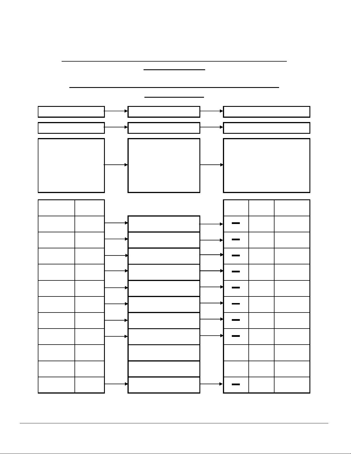
Sequence of Operation
The heating cycle start when a call for heat from the
thermostat supplies 24VAC to the TH terminal. The
automatic vent damper (if used) is energized and when
fully open, turns on the power to the ignition control. After
a 1 second maximum diagnostic period, the spark will
start and the pilot valve will turn on, starting with the trial
for ignition period.
During the trial for ignition period, the control sparks for 4
seconds while rapidly flashing LED. It then turns off the
spark and LED for 1 second while checking pilot flame
sense. This cycle will repeat until pilot flame is detected or
trial time is over.
When pilot flame is detected, the spark will stop, main
valve will turn on and the LED will stay on continuously.
The control will remain in this state until the pilot flame is
lost or the call for heat ends. If pilot flame is lost, LED,
main and pilot valves are turned off for 0.5 seconds and a
new trial for ignition sequence will start.
If pilot flame is not detected during the trial for ignition
period, the pilot valve will be shut off. Lockout will occur if
your model has no retry. For models with retry, the control
will wait for 5 minutes and then begin another
trial-for-ignition sequence.
Table 1: LED Indications During Normal Operation
Flash Code Flash Code Indication
Steady On Flame detected, main burner on
Troubleshooting
If the system does not function properly, determine the
cause using the procedures in this section.
Before proceeding with troubleshooting the system, check
the following.
Preliminary Checks
Are you using resistive wire between the module
spark (10) and the pilot connection?
Are all mechanical and electrical connections tight?
Is the system wired and ground correctly?
Is gas inlet pressure per manufacturer’s
specifications?
Is the system powered?
Is the thermostat calling for heat?
!
WARNING: Risk of Personal Injury.
Do not place face, hands, or other parts of the body in
or near the burner area when the LED is flashing
(recycle mode). When the LED is flashing, the control
may at any time (while in the recycle mode) re-energize
the burner control system and ignite the burner which
may result in electric shock from contact with the
electrode or severe burn injury from firing of the burner.
.1 Second On
.1 Second Off
.25 Second On
1.0 Second Off
Trial time spark on trying to light
pilot burner
Trial time lockout
6 BG1600M Intermittent Pilot Ignition Control with Rollout Switch Installation Instructions

LED Error Indications
If the control module’s internal diagnostics detect a fault it
will go into lockout. Spark and both valves will be turned
off. The LED will flash an error code .25 seconds on and
.25 seconds off for each count of the error code with
1 second off between codes. The control will remain in
this condition until power is removed by turning off the call
for heat. A flashing LED error code indicates either a
problem with wiring, or a component not working, or the
control module is faulty. Try to cycle the control again. If
the error repeats then see Table 2 for troubleshooting.
Table 2: LED Error Indications
Flash
Code
No
LED“ON”
Flash Code
Description
No Power
Troubleshooting Guide
1. Check for 24 volts on terminal 4 (24V/TH) and terminal 3 GND (24V).
2. Check for 24 volts on the secondary coil of the incomi ng transformer.
1. Check that the gas is turned “ON”.
2. If no spark, check spark wire and connection to terminal 10 (SPARK) and spark
ground to terminal 2 GND (BURNER).
3. Check for 24 volts on terminal 5 PV and terminal 1 GND (MV/PV).
4. Check for 24 volts at the PV coil.
5. Check that the PV is wired to terminal 5 (PV) and common is wired to terminal 1
GND (MV/PV).
1
No flame in
trial time
6. Check Flame Sensor tip is in the flame. For proper sensing the rod tip must be
3/8” (10 mm to 1/2” (13 mm) in the Flame.
7. Check Flame Sensor is wired to terminal 8 (SENSE) and terminal 2 GND (BURNER).
8. Check that the sense wire is not shorting to ground.
2
3
4
Flame sense
circuit error
PV
(Pilot Valve)
circuit error
MV
(Main Valve)
circuit error
1. Check if pilot flame is distinguished before the call-for-heat cycle is started.
1. Check for 24 volts on terminal 5 PV and terminal 1 GND (MV/PV).
2. Check for 24 volts at the PV coil.
3. Check that the PV is wired to terminal 5 PV and common is wired to terminal 1
GND (MV/PV).
1. Check for 24 volts on terminal 6 MV and terminal 1 GND (MV/PV).
2. Check for 24 volts at the MV coil.
3. Check that the MV is wired to terminal 6 (MV) and common is wired to terminal 1
GND (MV/PV).
1. Check for 24 volts on terminal 7 (R.O. SW) and termi nal 3 GND (24V).
2. Check that the rollout switch is wired to terminal 7 (R.O. SW) and the 24V thermostat
5 Rollout errors
line.
3. Check that the rollout switch has continuity because an “open” rollout switch will
cause an error.
1. Review all ground connections.
2. Check if using fiber core resistive wire for Spark Wire.
3. Software error – Restart control module.
1. Check for 24 volts on the secondary coil of the incoming transformer (+10%/-15%
rated voltage).
7
Solid
Red
Internal
Control error
Line
Frequency/
Voltage Error
NOTE: If Troubleshooting Guide has been used, and the Control Module is flashing an ERROR CODE, then the
Control Module may be faulty. Replace the Control Module.
BG1600M Intermittent Pilot Ignition Control with Rollout Switch Installation Instructions 7

Idle State
Call for heat
from the thermostat
If damper connected
wait for it to open
POWER TO CONTROL
One second for
diagnostic routines
Note:
If the thermostat opens,
the control will turn off valves
and returns to t he idle state.
Wait 0.1 second
checking memory and
relay driver circuits
Flame
on?
OK
No
Yes
FLAME ON
LOOP
If pre-pur ge wait
flashing LED once a
second unt il ov er
Turn on spark and
pilot gas valve
start trial timer
Spark on 4 seco nds
blinking LED rapidl y
spark off 1 second
Flame
on?
TRIAL
TIME
LOOP
Trial
No
over?
TRIAL
TIME
OVER
Tur n pilot gas
valve off
Retry
option?
Tries over
Wait 5 or 60 minutes,
blink LED ever y 15 seconds
Yes
No
Yes
Yes
Wait 0.5 second
Flame
No
on?
Yes
Tur n on main
gas valve and LED
reset try count
Lockout
RESTART
0.7 second?
RE-IGNITION
Yes
Re-Ignition
Turn main gas
valve off, st a r t spark
and trial timer
Turn p ilot and main
gas valves of f
wait 0.7 second
inte r - p u rge blinking
LED once a second
RELIGHT
Note: If the controller is flashing an error code, the control
will be in lockout. The controller will stay in lockout and continue
flashing a error code until power is cycled. If an error code repeats
then see Table 2 Troubleshooting Guid e to deter m ine
the problem.
Error Codes
No flame in trial time.
Flame sense stuck on .
Pilot relay driver fault.
Main rela y d r iver f ault.
Rollout err or.
Processor er r or s.
Line Frequency/
Voltage error.
Flame off
Yes
No
No
FLAME LOST
RECYCLE
LED Indicator
1 Blink
2 Blinks
3 Blinks
4 Blinks
5 Blinks
7 Blinks
Solid Red
Figure 2: Sequence of Operation
8 BG1600M Intermittent Pilot Ignition Control with Rollout Switch Installation Instructions

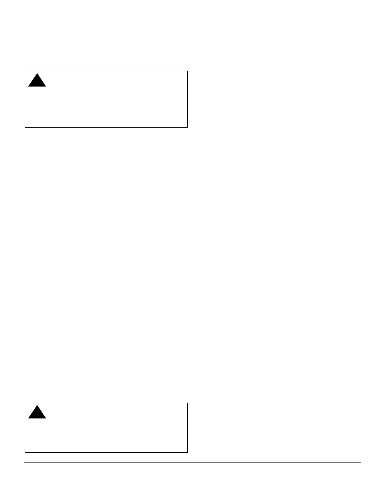
Turn on power
and gas.
Close thermostat
contacts.
Module LED
did not light and
no spark?
No
Module LED
blinks slowly?
No
Module LED
blinks rapidly but
no spark?
No
Pilot flame
does not
light?
No
Yes
Yes
Yes
Yes
Diagnostic error
see next page.
Replace module.
Spark wire
and electrode
OK?
No
Replace spa rk wire
or electrode.
24V between
PV and GND
terminals?
No
Replace
module.
Yes
Replace
module.
Yes
Gas at pilot
Adjust or replace spark
electro de and /or pilot
burner.
24V between
TH and GND
Connect pin 2-3
shor ting plug to
burner?
Yes
terminals?
Yes
Damper
used?
No
Shorting
plug in?
No
damper.
No
No
Check transformer,
thermostat and wiring.
Repair or replace as needed.
Yes
24V between
damper pin 2 & 4?
Yes
Yes
Check orfice and tubing are clear.
Replace
module.
Check shutoff valves are on.
Check wiring to pilot valve.
If all OK replace pilot valve.
No
Check and repair
damper, and/or
damper wiri ng.
Pilot lights
but keeps
sparking?
No
Pilot is lit
continued
on next page
Pilot flame in contact
with spark or sense
electrode?
Yes
Two rod
flame sense?
Yes
Check wiring electrode
to SENSE terminal.
If OK replace module.
NoYes
No
Check burner orifice.
Adjust pilot flame size or
electro de position.
Replace
module.
Figure 3: Troubleshooting Flow Chart (1 of 2)
BG1600M Intermittent Pilot Ignition Control with Rollout Switch Installation Instructions 9

Continued
from p revious page
Pilot is lit
Main burner
failed to turn
on?
No
After main is
lit, do valves turn off
and star t new
cycle?
No
Control is
operating
normally.
Yes
Yes
Yes
24V between
MV and MV/PV
terminals?
No
Replace
module.
Pilot flame in
contact with spark or
sense el ectrode?
Yes
Two rod
flame sense ?
Yes
Yes
No
No
Gas at main
burner?
Adjust pilot flame size
and posit ion, or replace
pilot burn er or m ain burner.
Adjust pilot flame size or
Replace
module.
No
Yes
electrode position.
Check that shutoff valves are on.
Check wiring to main valve.
Check tubing is clear.
If all OK replace main valve.
Check wiring electrode
to SENSE terminal.
If OK replace module.
Figure 4: Troubleshooting Flow Chart (2 of 2)
10 BG1600M Intermittent Pilot Ignition Control with Rollout Switch Installation Instructions

Maintenance Requirements in Severe
Environments
Regular preventive maintenance is important in any
application, but especially so in commercial cooking,
agricultural, and industrial applications because:
• In many such applications, particularly
commercial cooking, the equipment operates
100,000 to 200,000 cycles per year. Such heavy
cycling can wear out the gas control in one to
two years. A normal forced air furnace, for which
the controls were originally intended, typically
operates less than 20,000 cycles per year.
• Exposure to water, dirt, chemicals, and heat can
damage the ignition control module or the gas
control and shut down the control system. A
NEMA 4 enclosure can reduce exposure to
environmental contaminants.
!
WARNING: Risk of Explosion or Fire. Do
not attempt to take the ignition control module apart
or to clean it. Improper reassembly and cleaning
may cause unreliable operation, which can lead to
an explosion or fire, and may result in severe injury,
property damage or death.
Maintenance frequency must be determined
individually for each application. Some considerations
are:
• Cycling Frequency – Appliances that may cycle
more than 20,000 times annually should be
checked monthly.
• Intermittent Use – Appliances that are used
seasonally should be checked before shutdown
and again before the next use.
• Consequence of Unexpected Shutdown –
Where the cost of an unexpected shutdown
would be high, the system should be checked
more often.
Repairs and Replacement
!
CAUTION: Risk of Electric Shock.
Disconnect power supply before making electrical
connections to avoid electric shock.
!
WARNING: Risk of Explosion or Fire.
Shut off the gas supply at the main manual shutoff
valve before installing or servicing the control.
Failure to shut off the gas supply can result in the
release of gas during installation or servicing, which
can lead to an explosion or fire, and may result in
severe injury or death.
!
WARNING: Risk of Explosion, Fire, or
Electric Shock. Label all wires before they are
disconnected when replacing or servicing the
BG1600M. Wiring errors can cause improper or
dangerous operation and may result in an explosion,
fire, or electric shock leading to severe personal
injury or death.
Field repairs must not be made to the BG1600M
control. Any attempt to repair this assembly voids the
manufacturer’s warranty. For a replacement control,
contact the original equipment manufacturer or the
nearest BASO Gas Products distributor.
All other accessories, such as flame sensors,
electrode assembles, pilot assemblies, and leads can
be obtained through the original equipment
manufacturer or a BASO Gas Products distributor.
• Dust, Wet, or Corrosive Environment – Since
these environments can cause the controls to
deteriorate more rapidly, the system should be
checked more often.
BG1600M Intermittent Pilot Ignition Control with Rollout Switch Installation Instructions 11

Ignition Control Accessories
Table 3: Ignition Control Accessories
Part Number Description
RAA1600A-601D Rajah to 1/4” Spade Adapter (box of 50)
RAA1600A-601H Rajah to 1/4” Spade Adapter (bag of 10)
WHA40A-600D 18” Resistive Wire Harness with (2) 1/4” Terminals (box of 25)
WHA40A-600H 18” Resistive Wire Harness with (2) 1/4” Terminals (bag of 1)
WHA40A-601D 18” Resistive Wire Harness with (1) 1/4” Terminal and 1 Rajah Terminal (box of 25)
WHA40A-601H 18” Resistive Wire Harness with (1) 1/4” Terminal and 1 Rajah Terminal (bag of 1)
WHA40A-602D 24” Resistive Wire Harness with (2) 1/4” Terminals (box of 25)
WHA40A-602H 24” Resistive Wire Harness with (2) 1/4” Terminals (bag of 1)
WHA40A-603D 24” Resistive Wire Harness with (1) 1/4” Terminal and 1 Rajah Terminal (box of 25)
WHA40A-603H 24” Resistive Wire Harness with (1) 1/4” Terminal and 1 Rajah Terminal (bag of 1)
WHA40A-604D 36” Resistive Wire Harness with (2) 1/4” Terminals (box of 25)
WHA40A-604H 36” Resistive Wire Harness with (2) 1/4” Terminals (bag of 1)
WHA40A-605D 36” Resistive Wire Harness with (1) 1/4” Terminal and 1 Rajah Terminal (box of 25)
WHA40A-605H 36” Resistive Wire Harness with (1) 1/4” Terminal and 1 Rajah Terminal (bag of 1)
WHA40A-606D 48” Resistive Wire Harness with (2) 1/4” Terminals (box of 25)
WHA40A-606H 48” Resistive Wire Harness with (2) 1/4” Terminals (bag of 1)
WHA40A-607D 48” Resistive Wire Harness with (1) 1/4” Terminal and 1 Rajah Terminal (box of 25)
WHA40A-607H 48” Resistive Wire Harness with (1) 1/4” Terminal and 1 Rajah Terminal (bag of 1)
12 BG1600M Intermittent Pilot Ignition Control with Rollout Switch Installation Instructions

Notes
BG1600M Intermittent Pilot Ignition Control with Rollout Switch Installation Instructions 13

Notes
14 BG1600M Intermittent Pilot Ignition Control with Rollout Switch Installation Instructions

Technical Specification
Product
Ignition Type
Ignition Source
High Voltage Cable
BG1600M Intermittent Pilot Ignition Control with Rollout Switch
Indirect
High voltage spark, capacitive discharge
48 in. (1,220 mm) (Resistive wire recommended, rated for at least 15kV.)
Maximum Length
Flame Sense Cable
48 in. (1,220 mm)
Maximum Length
Flame Detection Means
Flame Detection Type
Minimum Flame Current
Flame Failure Response
Flame Rectification
Remote
0.15 microamperes
2 seconds maximum
Time
Maximum Spark Gap
Number of Trials Before
0.2 in. (5.1 mm)
One
100% Shutoff
Trial-for-Ignition Time
Prepurge Time
Inter-Purge Time
Automatic Recycle Delay
85 seconds
0 or 15 seconds
15 seconds
None or 5 minutes
Period
Power Requirements
Contact Rating
Wiring Connections
Maximum Firing Rate
Ambient Operating and
Control:
Operation Current:
Main Valve:
Pilot Valve:
24 VAC (+10%/-15%), 50/60 Hz
0.2 A nominal + valves
4 A maximum
2 A maximum
1/4 in. (6.35 mm) male spade
400,000 Btu/hr (117 kW)
-40 to 170°F (-40 to 77°C)
Storage Temperature
Humidity
Type of Gas
Packaging
95% RH noncondensing
Natural, Liquefied Petroleum (LP), Manufactured, Mixed or LP Gas-Air Mixture
Individual pack (1 per box)
Individual overpack (20 per box)
Pack Weight
Individual pack 1 lb (.454 kg)
Individual overpack 18 lb (8.17 kg)
Agency Listing
Specifications Standards
CSA Certificate Number Pending
ANSI Standard Z21.20
CAN/CSA-C22.2 No. 199
The performance specifications are nominal and conform to acceptable industry standards. All agency certification of BASO products is
performed under dry and controlled indoor environmental conditions. Use of BASO products beyond these conditions is not recommended and
may void the warranty. If the product is exposed to water (dripping, spraying, rain, etc.) or other harsh environments, it must be protected. The
original equipment manufacturer or end user is responsible for the correct application of BASO products. For questionable applications, please
consult BASO Gas Products LLC. BASO Gas Products LLC shall not be liable for damages or product malfunctions resulting from
misapplication or misuse of its products.
1007 South 12th Street
PO Box 170
Watertown, WI 53094 Published in U.S.A.
1-877-227-6427 www.baso.com
BG1600M Intermittent Pilot Ignition Control with Rollout Switch Installation Instructions 15
 Loading...