

Page 1
Installation Instructions
Issue Date June 26, 2014
BG1100M Direct Spark Ignition Control
Application
The BG1100M is a microprocessor based ignition
control. The microprocessor provides reliable software
control of all timings and operates a diagnostic red
Light-Emitting Diode (LED). It is designed for direct
burner supervision and can be used with all gases. It
provides ignition sequence, flame monitoring, and
safety shutoff for direct spark ignition boilers, furnaces
and other heating appliances. For a complete listing of
specifications, refer to the Technical Specifications
section.
Installation
IMPORTANT: Only qualified personnel should
install or service BASO Gas Products®. These
instructions are a guide for such personnel. Carefully
follow all instructions for the appliance.
IMPORTANT: Make all gas installations in
accordance with applicable local, national, and
regional regulations.
Instructions for installing the burner/igniter-sensor are
typically provided by the appliance manufacturer. It is
important to follow those instructions. If such
information is not included, refer to the Mounting
section.
Mounting
!
CAUTION: Risk of Electric Shock.
Disconnect power supply before making electrical
connections to avoid electric shock.
!
WARNING: Risk of Explosion or Fire.
Shut off the gas supply at the main manual shutoff
valve before installing or servicing the control.
Failure to shut off the gas supply can result in the
release of gas during installation or servicing, which
can lead to an explosion or fire, and may result in
severe personal injury or death.
!
WARNING: Risk of Explosion or Fire.
Do not install the control in an area that is exposed
to water (for example, dripping, spraying, rain). Do
not use the control if it has been exposed to water.
Exposure to water may cause malfunction and can
lead to an explosion or fire and may result in severe
personal injury or death.
IMPORTANT: This control is approved for use
with only noise suppression (resistive) spark wires. If
the application has copper wire, it must be replaced.
© 2014 BASO Gas Products. 1
Part No. BASO-INS-BG1100M, Rev. E www.baso.com
IMPORTANT: Do not mount the control where
it can be exposed to direct infrared radiation from the
main burner or to temperatures in excess of the
maximum product temperature rating.
Page 2

Location Considerations
Choose a location that provides the shortest, direct
cable route to the spark electrode, pilot burner/ignitersensor assembly. Easy access to the terminals is
desired for wiring and servicing. The control may be
mounted in any position. Mount the control on a
grounded metal surface with #6 sheet metal or
machine screws through the mounting holes provided
in the enclosure.
The pilot burner/igniter sensor must be securely
mounted to the main burner to ensure that the pilot
burner flame remains properly positioned with respect
to the main burner flame. The pilot burner must be
located such that the flame receives an ample supply
of air, free from the products of combustion, the flame
must not be exposed to draft conditions, the full force
must not be exposed to draft conditions, the full force
of main burner ignition, or falling scale, which could
otherwise impede ignition of main burner flame.
Securely mount the pilot burner/igniter-sensor to the
main burner with metal screws at a distance
approximately 3/8 in. (9.52 mm) above and 1/4 in.
(6.35 mm) away from the center of the nearest main
burner port. Ensure that the main burner flames do not
impinge on any part of the pilot burner.
The spark electrode, flame sensor, and BG1100M
must share a common ground with the burner to
operate correctly. Thermoplastic insulated wire with a
minimum rate of 221˚F (105˚C) is recommended for
the ground wire. Ensure that the flame sensor wire and
the high voltage spark transformer wire are separated
from one another by a minimum distance of 1/4 in.
(6.35 mm) and are not wrapped around any pipe, other
wiring, or accessory.
Wiring
!
WARNING: Risk of Explosion or Fire.
Locate all safety, limit, and operating controls in
series with the thermostat terminal (TH) on the
ignition control. Improper installation may cause gas
leaks, which can lead to an explosion or fire and
may result in severe personal injury or death.
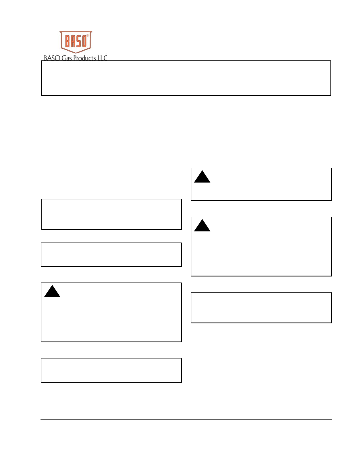
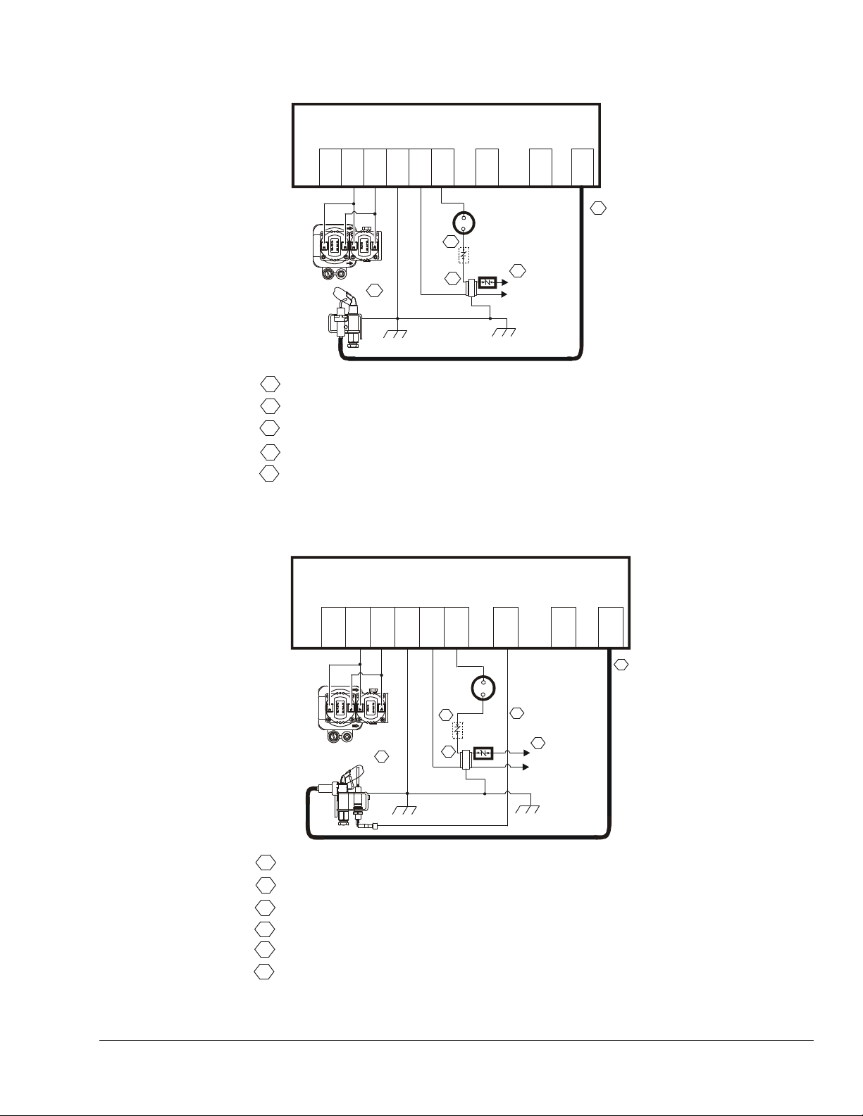
Refer to Figure 1 and Figure 2 for wiring diagrams. All
wiring should be in accordance with the National
Electrical Code (NEC) and all other local codes and
regulations.
Check the voltage rating marked on the control and
make sure it is suited to the application. Use a Class 2
transformer capable of providing 24 VAC under
maximum load, including valves. A transformer having
excessive primary impedance due to poor coupling
affects the ignition potential.
The high-voltage spark transformer cable is noise
suppression (resistive) type, rated for at least 15kVA
and must not be in continuous contact with a metal
surface. Use standoff insulators. Ensure that the flame
sensor wire and high voltage spark transformer cable
are separated from one another by a minimum of 1/4
in. (6.35 mm) and are not wrapped around any pipe,
other wiring, or accessories.
!
WARNING: Risk of Electric Shock.
Before applying power to the control, connect the
high voltage cable to the spark transformer terminal
and spark electrode (pilot burner assembly). Verify
the ground wire is attached to the pilot burner and
the control ground terminal strip. Failure to follow
this procedure can cause electric shock and may
result in severe personal injury or death.
2 BG1100M Direct Spark Ignition Control Installation Instructions
Page 3
VALVE
2
GND
(COM)
VALVE
3456 8 10
24V
GND
BURNER
SENSE
SPARK
Thermostat
Combination
Gas Valve
5
Burner/ignitor
1
Power Supply. Provides disconnect means and overload protection as required.
Maximum cable length 48 inches (1,220 mm). (Resistive wire recommended.)
2
3
Alternate location for limit controller.
4
Controls in 24V circuit must not be in ground leg to transformer.
5
Sensor rod must be 3/8” (9.53 mm) to 1/2” (12.7 mm) of the sensor tip should
3
4
24VAC
Class 2
Transformer
Chassis or Frame
Ground
High
Tem p
Limit
1
L1 (Hot)
L2 (Neu)
2
be in the flame for proper sensing signal.
Figure 1: Wiring for 1 Rod Flame Sense
VALVE
(COM)
234
GND
VALVE
GND
BURNER
56
24V
SENSE
8
SPARK
10
Thermostat
Combination
Gas Valve
6
Burner/Ignitor
1
Power Supply. Provides disconnect means and overload protection as required.
Maximum cable length 48 inches (1,220 mm). (Resistive wire recommended.)
2
3
Alternate location for limit controller.
4
Controls in 24V circuit must not be in ground le g to transform er.
5
Maximum cabl e le ngth 48 inches (1, 220 mm).
Sensor rod m ust be 3/8” (9.53 m m ) t o 1/ 2” (12.7 mm) o f the sensor tip should
6
be in the flam e for proper sensin g si gnal.
Flame
Sensor
3
4
24VAC
Class 2
Transformer
Chassis or Frame
Ground
High
Temp
Limit
5
1
L1 (Hot)
L2 (Neu)
Figure 2: Wiring for 2 Rod Flame Sense
BG1100M Direct Spark Ignition Control Installation Instructions 3
2
Page 4

Setup and Adjustments
Operation
Checkout
!
WARNING: Risk of Explosion or Fire. Verify
that there are no gas leaks by testing with appropriate
equipment. Never use a match or lighter to test for the
presence of gas. Failure to test properly can lead to an
explosion or fire and may result in severe personal injury
or death.
Make sure all components function properly by performing
the following test.
1. Before starting the appliance, perform a safety
inspection of piping, burners and venting. Check for
water leaks, etc. Check all wiring for proper
connections. Be sure the system is properly
grounded, including ground connection to the pilot
burner.
2. With the gas and thermostat off, turn on power to the
appliance.
3. Turn the thermostat to a high setting and verify that
the control goes through the operating sequence to a
shutoff condition.
Note: The burner does not light because the gas is
off.
4. Turn off the thermostat.
5. Turn on the gas and purge gas lines of all air.
6. Check for gas leaks on all pipe joints upstream of the
gas valve with a soap solution.
7. Turn the thermostat to the highest setting and verify
successful ignition and a normal run condition for at
least 5 minutes. If the appliance fails to run, see the
Troubleshooting section.
8. Check for gas leaks on all pipe joints downstream of
the gas valve with a soap solution.
9. Turn the thermostat down for at least 30 seconds
and then back up again. Verify successful ignition at
least five times.
10. Return the thermostat to a normal temperature
setting before leaving the installation.
IMPORTANT: Only qualified personnel should
install or service BASO Gas Products®. If any faults are
detected, see Troubleshooting Table 2. If control
module has been opened or any attempts to repair are
done, the warranty is void.
Table 1: Red LED Indications, Normal Operation
Flash Code Flash Code Indication
Steady On Flame detected, main burner on
0.1 Second On
0.1 Second Off
0.5 Second On
0.5 Second Off
1.0 Second On
4.0 Second Off
Sequence of Operation
The heating cycle starts when a call for heat from the
thermostat supplies 24VAC to the 24V/TH terminal. After
a 1 second maximum diagnostic period, the control enters
pre-purge mode, after pre-purge time, the spark starts
and the gas valve opens, starting with the trial for ignition
period. If no pre-purge, trial for ignition mode begins
immediately (see Table 1 for red LED normal operation).
During the trial for ignition period, the control sparks while
rapidly flashing red LED. It then turns off the spark and
red LED while checking pilot flame sense. This cycle will
repeat until pilot flame is detected or trial time is over.
When pilot flame is detected, the spark stops, the gas
valve remains open and the red LED stays on
continuously. The control will remain in this state until the
pilot flame is lost or the call for heat ends. Model with no
inter-purge, if the pilot flame is lost, the gas valve
remains open and a new trial for ignition will start. Model
with inter-purge, if flame is lost within 5 seconds of an
established flame, the gas valve remains open; the control
initiates sparking, and begins a trial for ignition period
immediately. If flame is lost after 5 seconds of an
established flame, the gas valve will close, and the control
initiates the inter-purge time delay before beginning
another trial for ignition period. Model with no retry and
one trial, if pilot flame is not detected during the trial for
ignition period, the gas valve will close. Lockout will occur
and a red LED will flash indicating an error (see Table 2
for proper diagnostics of the error). Remove power to end
lockout. Model with retry and three trials, if flame is not
sensed by the end of the trial for ignition time period, the
gas valve will close and the control module will initiate an
inter-purge time delay, followed by another trial for ignition
period (this occurs up to three trials). After the third trial,
the control will initiate a 5 minute retry period. If flame is
not sensed, the ignition sequence will repeat, until flame is
sensed. If flame still is not sensed, remove power to reset
the ignition.
Trial time spark on trying to light
pilot burner
Pre-Purge or Inter-Purge Time
Retry or Recycle Time
4 BG1100M Direct Spark Ignition Control Installation Instructions
Page 5

Troubleshooting
If the system does not function properly, determine the
cause using the procedures in this section.
Before proceeding with troubleshooting the system, check
the following.
Preliminary Checks
Are you using resistive wire between the module
spark (10) and the pilot connection?
Are all mechanical and electrical connections tight?
Is the system wired and ground correctly?
Is gas inlet pressure per manufacturer’s
specifications?
Is the system powered?
Is the thermostat calling for heat?
!
WARNING: Risk of Personal Injury.
Do not place face, hands, or other parts of the body in
or near the burner area when the red LED is flashing
(retry mode). When the red LED is flashing, the control
may at any time (while in the retry mode) re-energize
the burner control system and ignite the burner which
may result in electric shock from contact with the
electrode or severe burn injury from firing of the burner.
Red LED Error Indications
If the control module’s internal diagnostics detect a fault it
will go into lockout. Spark and both valves will be turned
off. The red LED will flash an error code .25 seconds on
and .25 seconds off for each count of the error code with
1 second off between codes. The control will remain in
this condition until power is removed by turning off the call
for heat. A flashing red LED error code indicates either a
problem with wiring, or a component not working, or the
control module is faulty. Try to cycle the control again. If
the error repeats then see Table 2 for troubleshooting.
BG1100M Direct Spark Ignition Control Installation Instructions 5
Page 6

Table 2: Red LED Error Indications
Flash
Code
Flash Code
Description
Troubleshooting Guide
No
LED
“ON”
No Power
1. Check for 24 volts on terminal 6 (24V) and terminal 5 (GND).
2. Check for 24 volts on the secondary coil of the incomi ng transformer.
1. Check if the gas is turned “ON”.
2. Check for 24 volts on terminal 6 (24V) and terminal 5 (GND).
1
No flame in
trial time
3. If no spark, check spark wire and connection to terminal 10 (SPARK) and spark
ground terminal 4 (GND BURNER).
4. Check if valve is wired to terminal 3 (VALVE) and common is wired to terminal 2
(VALVE COM).
5. Check for 24 volts at Valve’s coil.
1. Check Flame Sensor tip is in the flame. For proper sensing the rod tip must be
3/8” (10mm) to 1/2” (13 mm) in the flame.
2
Flame sense
circuit error
2. Check Flame Sensor circuits;
2.1. For 1 Rod Flame Sense circuit, check Spark/Flame Sensor is wired to terminal
10 (SPARK) and terminal 4 (GND BURNER).
2.2. For 2 Rod Flame Sense circuit, check Flame Sensor is wired to terminal 8
(SENSE) and terminal 4 (GND BURNER).
1. Check for 24 volts on terminal 3 (VALVE) and terminal 2 (VALVE COM).
2. Check if valve is wired to terminal 3 (VALVE) and common is wired to terminal 2
3
Valve circuit
error
(VALVE COM).
3. Check for 24 volts at the Valve’s coil.
4. Check gas valve connections and terminals.
5. Check gas valve coil current.
1. Review all ground connections and terminals. Make sure you have good
continuity on all of the ground wires (See Ground Continuity Check for details).
2. Check that the Spark Wire is not touching any other control wires and/or metal
5 to 9 Control error
frame. The Spark Wire should be isolated 3/8” to 1/2” away from all other control
wires and metal frame (chassis).
3. Check if using fiber core resistive wire for the Spark Wire.
4. Try restarting the power (Call to Heat) to the control module.
5. All ground connections should be cleaned and rust free.
NOTE: If Troubleshooting Guide has been used, and the Control Module is flashing an ERROR CODE, then the
Control Module may be faulty. Replace the Control Module.
NOTE: Ground Continuity Check:
Perform a continuity check on each of the 3 ground wires which are needed and going to the Control Module.
First, turn power off to the ignition module. With a Multi-Meter on ohm’s scale, place a meter’s test probe on any
of the grounds at the Controls Module. With the other Meter’s test probe, place it at the following ground
terminations of each wire:
1. Transformer Ground (COM)
2. Gas Valve (COM)
3. Burner Frame (COM)
Each wire measure should read less than 1 ohm of resistance. If any wire reads more than 1 ohm of resistance,
this is a problem. Replace wire or connections until less than 1 ohm is read on the continuity check.
6 BG1100M Direct Spark Ignition Control Installation Instructions
Page 7

Idle State
Call for heat
from the thermostat
POWER TO CONTROL
One second for
diagnost ic routines
Note:
If the thermostat opens,
the control will turn off valve
and returns to the idle state.
Wait 0.1 second
checking m emory and
relay driver circuits
OK
Flame
on?
FLAME ON
LOOP
Yes
No
If pre-pu r ge wait
flashing red LED once a
0.5 second until over
Turn on spa r k and
gas valve
start trial timer
Spark on 4 seconds
blinking red LED rapidly
spark off 1 second
TRIAL
TIME
LOOP
No
TRIAL
TIME
OVER
Flame
on?
Trial
over?
Tur n ga s
valve of f
Yes
No
Yes
Wait 0.5 second
Flame
No
on?
Yes
Turn on red LED
Flame off
0.7 second?
Turn gas valve off
wait 0.7 second or
inter-p ur ge blinking
red LED once a 0.5 second
RE-LIGHT
No
FLAME LOST, TURN
Yes
OFF VALVES AND
TRY TO RE-LIGHT
Note:
Lock out on timeout or fault detected,
turn off valve rel ays and spar k l oop blink ing
error code until power off.
Error Codes
No flame in trial time.
Flame sense stuck on .
Valve relay driver fault.
Processor errors.
1 Blink
2 Blinks
3 Blinks
5 to 9 Blinks
Retry
option?
Wait 5 minut es, blink
red LED every 4 seconds
No
Yes
Lockout
RESTART
Figure 3: Sequence of Operation
BG1100M Direct Spark Ignition Control Installation Instructions 7
Page 8

Turn on power
and gas.
Close thermostat
contacts.
Module red LED
did not light and
no spark?
No
Module red LED
blinks slowly?
No
Module red LED
blinks rapidly but
no spark?
No
Flame
does not
light?
No
Yes
Yes
Yes
Yes
Diagnostic error
see next page.
Replace mod ule.
Spark wire
and electrode
OK?
No
Replace spark wire
or electrode.
24V between
valve and GND
terminals?
No
Replace
module.
Yes
Replace
module.
Yes
burner?
Adjust or replace spark
electrode and/or pilot
burner.
Gas at
Yes
24V between
TH and GND
terminals?
Yes
Replace
module.
No
No
Check transformer,
thermostat and wiring.
Repair or replace as needed.
Check shutoff valves are on.
Check wiring to valve.
Check orifice and tubing are clear.
If all OK replace pilot valve.
Burner lights
but keeps
sparking?
No
Burner is lit
continued
on next page
Yes
Burner flame in contact
with spark or sense
electrode?
Yes
Two rod
flame sense?
Yes
Check wiring electrode
to SENSE terminal.
If OK replace module.
No
No
Check burner orifice.
Adjust pilot flame size or
electro de pos it ion.
Replace
module.
Figure 4: Troubleshooting Flow Chart (1 of 2)
8 BG1100M Direct Spark Ignition Control Installation Instructions
Page 9

Continued
from previous page
Pilot is lit
After burner is
lit, do valves turn off
and star t new
cycle?
No
Control is
operating
normally.
Yes
Flame in
contact with spark or
sense electrode?
Yes
Two rod
flame sens e?
Yes
Check wiring electrode
to SENSE terminal.
If OK replace module.
No
No
Replace
module.
Figure 5: Troubleshooting Flow Chart (2 of 2)
Adjust flame size or
electrode position.
BG1100M Direct Spark Ignition Control Installation Instructions 9
Page 10

Maintenance Requirements in Severe
Environments
Regular preventive maintenance is important in any
application, but especially so in commercial cooking,
agricultural, and industrial applications because:
• In many such applications, particularly
commercial cooking, the equipment operates
100,000 to 200,000 cycles per year. Such heavy
cycling can wear out the gas control in one to
two years. A normal forced air furnace, for which
the controls were originally intended, typically
operates less than 20,000 cycles per year.
• Exposure to water, dirt, chemicals, and heat can
damage the ignition control module or the gas
control and shut down the control system. A
NEMA 4 enclosure can reduce exposure to
environmental contaminants.
!
WARNING: Risk of Explosion or Fire. Do
not attempt to take the ignition control module apart
or to clean it. Improper reassembly and cleaning
may cause unreliable operation, which can lead to
an explosion or fire, and may result in severe injury,
property damage or death.
Maintenance frequency must be determined
individually for each application. Some considerations
are:
• Cycling Frequency – Appliances that may cycle
more than 20,000 times annually should be
checked monthly.
• Direct Spark Use – Appliances that are used
seasonally should be checked before shutdown
and again before the next use.
• Consequence of Unexpected Shutdown –
Where the cost of an unexpected shutdown
would be high, the system should be checked
more often.
Repairs and Replacement
!
CAUTION: Risk of Electric Shock.
Disconnect power supply before making electrical
connections to avoid electric shock.
!
WARNING: Risk of Explosion or Fire.
Shut off the gas supply at the main manual shutoff
valve before installing or servicing the control.
Failure to shut off the gas supply can result in the
release of gas during installation or servicing, which
can lead to an explosion or fire, and may result in
severe injury or death.
!
WARNING: Risk of Explosion, Fire, or
Electric Shock. Label all wires before they are
disconnected when replacing or servicing the
BG1100M. Wiring errors can cause improper or
dangerous operation and may result in an explosion,
fire, or electric shock leading to severe personal
injury or death.
Field repairs must not be made to the BG1100M
control. Any attempt to repair this assembly voids the
manufacturer’s warranty. For a replacement control,
contact the original equipment manufacturer or the
nearest BASO Gas Products distributor.
All other accessories, such as flame sensors,
electrode assembles, pilot assemblies, and leads can
be obtained through the original equipment
manufacturer or a BASO Gas Products distributor.
• Dust, Wet, or Corrosive Environment – Since
these environments can cause the controls to
deteriorate more rapidly, the system should be
checked more often.
10 BG1100M Direct Spark Ignition Control Installation Instructions
Page 11

Table 3: Ignition Control Accessories
Part Number Description
RAA1600A-601D Rajah to 1/4” Spade Adapter (box of 50)
RAA1600A-601H Rajah to 1/4” Spade Adapter (bag of 10)
WHA40A-600D 18” Resistive Wire Harness with (2) 1/4” Terminals (box of 25)
WHA40A-600H 18” Resistive Wire Harness with (2) 1/4” Terminals (bag of 1)
WHA40A-601D 18” Resistive Wire Harness with (1) 1/4” Terminal and 1 Rajah Terminal (box of 25)
WHA40A-601H 18” Resistive Wire Harness with (1) 1/4” Terminal and 1 Rajah Terminal (bag of 1)
WHA40A-602D 24” Resistive Wire Harness with (2) 1/4” Terminals (box of 25)
WHA40A-602H 24” Resistive Wire Harness with (2) 1/4” Terminals (bag of 1)
WHA40A-603D 24” Resistive Wire Harness with (1) 1/4” Terminal and 1 Rajah Terminal (box of 25)
WHA40A-603H 24” Resistive Wire Harness with (1) 1/4” Terminal and 1 Rajah Terminal (bag of 1)
WHA40A-604D 36” Resistive Wire Harness with (2) 1/4” Terminals (box of 25)
WHA40A-604H 36” Resistive Wire Harness with (2) 1/4” Terminals (bag of 1)
WHA40A-605D 36” Resistive Wire Harness with (1) 1/4” Terminal and 1 Rajah Terminal (box of 25)
WHA40A-605H 36” Resistive Wire Harness with (1) 1/4” Terminal and 1 Rajah Terminal (bag of 1)
WHA40A-606D 48” Resistive Wire Harness with (2) 1/4” Terminals (box of 25)
WHA40A-606H 48” Resistive Wire Harness with (2) 1/4” Terminals (bag of 1)
WHA40A-607D 48” Resistive Wire Harness with (1) 1/4” Terminal and 1 Rajah Terminal (box of 25)
WHA40A-607H 48” Resistive Wire Harness with (1) 1/4” Terminal and 1 Rajah Terminal (bag of 1)
BG1100M Direct Spark Ignition Control Installation Instructions 11
Page 12

Notes
12 BG1100M Direct Spark Ignition Control Installation Instructions
Page 13

Notes
BG1100M Direct Spark Ignition Control Installation Instructions 13
Page 14

Notes
14 BG1100M Direct Spark Ignition Control Installation Instructions
Page 15

Technical Specification
Product
Ignition Type
Ignition Source
High Voltage Cable
Maximum Length
Flame Sense Cable
Maximum Length
Flame Detection Means
Flame Detection Type
Minimum Flame Current
Flame Failure Response
Time
Maximum Spark Gap
Number of Trials Before
100% Shutoff
Trial-for-Ignition Time
Prepurge Time
Inter-Purge Time
Retry (Recycle) Delay
Period
Power Requirements
Contact Rating
Wiring Connections
Maximum Firing Rate
Ambient Operating and
Storage Temperature
Humidity
Type of Gas
Packaging
Bulk Pack Quantity
Pack Weight
Agency Listing
Specifications Standards
The performance specifications are nominal and conform to acceptable industry standards. All agency
certification of BASO products is performed under dry and controlled indoor environmental conditions. Use of
BASO products beyond these conditions is not recommended and may void the warranty. If the product is
exposed to water (dripping, spraying, rain, etc.) or other harsh environments, it must be protected. The original
equipment manufacturer or end user is responsible for the correct application of BASO products. For questionable
applications, please consult BASO Gas Products LLC. BASO Gas Products LLC shall not be liable for damages
or product malfunctions resulting from misapplication or misuse of its products.
BG1100M Direct Spark Ignition Control
Direct
High voltage spark, capacitive discharge
48 in. (1,220 mm) (Resistive wire only, rated for at least 15kV.)
48 in. (1,220 mm)
Flame Rectification
Local or Remote
0.15 microamperes
2 second maximum
0.2 in. (5.1 mm)
One or Three
4, 8, 10 or 20 seconds
0 (none), 15 or 30 seconds
0 (none) or 30 seconds
0 minutes (none)
5 minutes
Control:
Operation Current:
Valve: 2 A maximum
1/4 in. (6.35 mm) male spade
400,000 Btu/hr (117 kW)
-40 to 170°F (-40 to 77°C)
95% RH noncondensing
Natural, Liquefied Petroleum (LP), Manufactured, Mixed or LP Gas-Air Mixture
Bulk pack supplied to original equipment manufacturer (individual pack option al)
25
14 lb (6.36 kg)
CSA Certificate Number 246569-2161442
ANSI Standard Z21.20
CAN/CSA-C22.2 No. 199
24 VAC (+/- 20%), 50/60 Hz
0.2 A nominal + valves
1007 South 12th Street
PO Box 170
Watertown, WI 53094 Published in U.S.A.
1-877-227-6427 www.baso.com
BG1100M Direct Spark Ignition Control Installation Instructions 15
 Loading...