

Page 1

BEST IDEAS FOR IP
INTERCOM SOLUTIONS
Page 2

2
Note
For the correct installation, follow the instructions. If you have any difficulty with
installation and operation, please contact your dealer for advice. The technical
parameters and specifications mentioned here may vary slightly from those
stated in the instructions of the devices. This is our company conducts constant
upgrading and improvement of the functionality to improve the characteristics
of current devices.
Page 3

CONTENT
Individual outdoor panels
Appearance ...............................................................................................................
Main functions ..........................................................................................................
Technical parameters ............................................................................................
Equipment .................................................................................................................
Setting through WEB interface .........................................................................
Connection scheme ...............................................................................................
Mounting ....................................................................................................................
Multi apartment outdoor panels
Appearance ...............................................................................................................
Connection ................................................................................................................
Equipment .................................................................................................................
Setting through WEB interface .........................................................................
Connection scheme ...............................................................................................
Mounting ....................................................................................................................
Internal monitors
Appearance ...............................................................................................................
Main functions ..........................................................................................................
Technical parameters ............................................................................................
Setting through WEB interface .........................................................................
Connection scheme ...............................................................................................
Installation .................................................................................................................
Concierge monitor
Appearance ...............................................................................................................
Main functions ..........................................................................................................
Technical parameters .............................................................................................
Conguration via the monitor’s graphic interface ......................................
Setting through WEB interface .........................................................................
Connection scheme ................................................................................................
Appearance ...............................................................................................................
Main functions ..........................................................................................................
Technical parameters ............................................................................................
Conguration via the monitor’s graphic interface ......................................
Notes ............................................................................................................................
3
4
4
5
6
6
11
14
16
17
17
18
25
28
29
30
30
31
38
39
40
41
41
42
47
51
52
53
53
54
57
Page 4
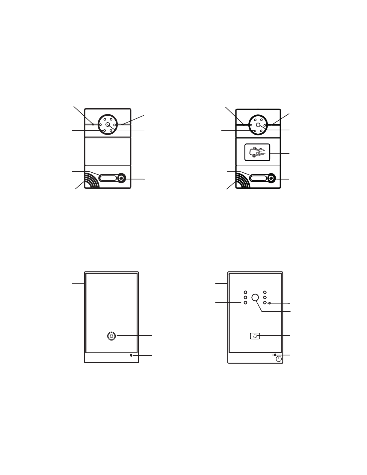
APPEARANCE
Model AV-01 (v2.0 and v3.0 SIP) Model AV-01T (v2.0 and v3.0 SIP)
Model: AV-02 v3.0 SIP
LIGHT SENSOR
MICROPHONE
CAMERABACKLIGHT
RING BUTTON
LOUDSPEAKER
RING BUTTON
RING BUTTON
CAMERA
CAMERA
LIGHT SENSOR
LIGHT SENSOR
BACKLIGHT
READER FOR
CONTACTLESS
CARDS
IN A FIRE
PRESS TO COMMUNICATE
WITH A DISPATCHER
Model: AV-02FP
4
LIGHT SENSOR LIGHT SENSOR
BACKLIGHT
SIGN WITH THE
NUMBER
LOUDSPEAKER
SIGN WITH THE
NUMBER
MICROPHONE
MICROPHONE
RING BUTTON
MICROPHONE
Page 5

MAIN FUNCTIONS
Interface
WEB-interface
Lock opening
By card, with the monitor
Access control
Reader for contactless cards
EM-Marin or MIFARE
Integration with ACS
Output WIEGAND-26
Buttons for quick dialing
1 call button
Number of ringtones
4 polyphonic ringtones
Authentication
WEB-interface
Talking mode
Double-sided
Talking time
Up to 240 seconds
Additional functions
SIP P2P
Place for the signature near the call
button
Stores up to 10,000 cards
Recording cards available through software
or using master card
TECHNICAL PARAMETERS
Panel type
Individual
Screen
No
Camera
1/3”, adjustment of the camera
direction
Angle
71° horizontal × 56° vertical
Resolution
800 TVL
Output video
D1 (704×576), H.264 Main Prole,
BaseLine Prole
Night backlight
6 LEDs
Light sensitivity
0,01 lux
Protection class
IP65
Operating temperature
-40 – +65 °C
Power consumption
5,5 W, in standby – 2,5 W
Power
+ 12 V
Body
Metal
Colors
Titanium-grey
Dimensions for installation
180×104×60 mm
Dimensions of panel
192×116×45 мм
Installation
Flush mount, wall mount
5
Page 6
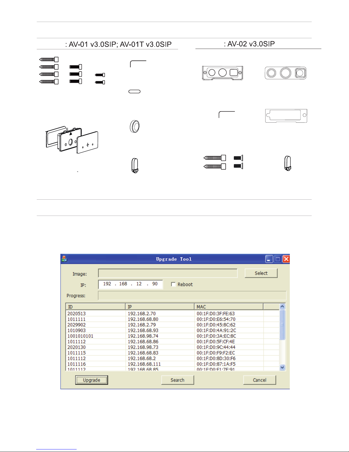
EQUIPMENT
SETTING THROUGH WEB INTERFACE
Search for the IP-address of the outdoor panel.
After you have connected the outdoor panel in the same local area network as
your computer, run the program «Upgrade Tool» to determine the IP-address of
the outdoor panel.
Press the “Search” button and the program window will display the IP-address
of the outdoor panel and any other devices BAS-IP, which are connected to the
local network.
Model
Model
MOUNTING
SCREWS
KEY
PROTECTIVE
COVER
WATERPROOF CAP
AND PROTECTIVE CABLE COVER 1
PROTECTIVE
CABLE COVER 2
PROTECTIVE
CABLE COVER 3
KEY
PROTECTIVE
CABLE COVER 2
MOUNTING
SCREWS
PROTECTIVE
CABLE COVER 3
WATERPROOF CAP
AND PROTECTIVE
CABLE COVER 1
PROTECTIVE CABLE
COVER 1
Page 7

To congure the outdoor panel through the WEB-interface, you must connect to
it sing a web browser on a PC. The panel must be
connected to the same local network segment as the PC from which you plan
to make the settings. In the Internet browser in the address bar enter the IP-address of the outdoor panel, and then enter your username and password. The
username to enter the settings: admin. The password required for entry must
match the password for access to the outdoor panel settings and is an installer’s
password, default: 123456.
1. Network Settings.
Select «Network» to access the network conguration settings:
7
SETTING THROUGH WEB INTERFACE
2. Device Settings.
Select «Device» to access the conguration of the Logical address, the operat-
ing mode and ringtones:
Page 8

SETTING THROUGH WEB INTERFACE
BuildNo: Specify the house number.
UnitNo: Specify the entrance number.
Floor: Specify the number of the oor.
RoomNo: Specify the number of the apartment.
No: Specify the outdoor panel serial number.
Panel mode: Set the operating mode «Personal Panel». The number of the
building, entrance, oor, and apartment must match the address of the internal
monitor, which will receive a call from this outdoor panel. If you have several
outdoor panels that have one logical address, then in the “No” eld, enter a value
of 2, 3, 4, 5 and so on, until 9. If the logical address of the outdoor panel
corresponds to the logical address of the monitor, and the IP addresses of
the devices are in the same network segment – the devices will nd each other,
and the call will occur correctly.
3. Registration of contactless cards via WEB-interface.
Enter in the “Master-card” number 0, and then click “Apply”. Within 20 seconds,
bring the required registration master card to the area of the outdoor panel’s
reader – an alarm sounds ”BEEP”, which means that the master-card has been
registered successfully. Now, each user card can be brought to the panel’s reader.
After each user card, ”BEEP” will sound which indicates a successful registration
of the card. The time between adding cards should not exceed 10 seconds.
4. SIP settings.
Select «VOIP» for the transition to SIP account settings:
8
Page 9
SETTING THROUGH WEB INTERFACE
Proxy: SIP-server address. It can be specied as the IP address and the domain
name. For example: sip: 192.168.1.99, or sip: sip.linphone.org.
Domain: The domain address of the SIP-server is often the same as the IP
address of the SIP-server. Password: Enter the password for the SIP-account
(SIP-number).
Stun IP and Stun Port: indicates if this outdoor panel is mounted after NAT, for
example, a router. Username: indicated directly SIP-account (SIP-number).
9
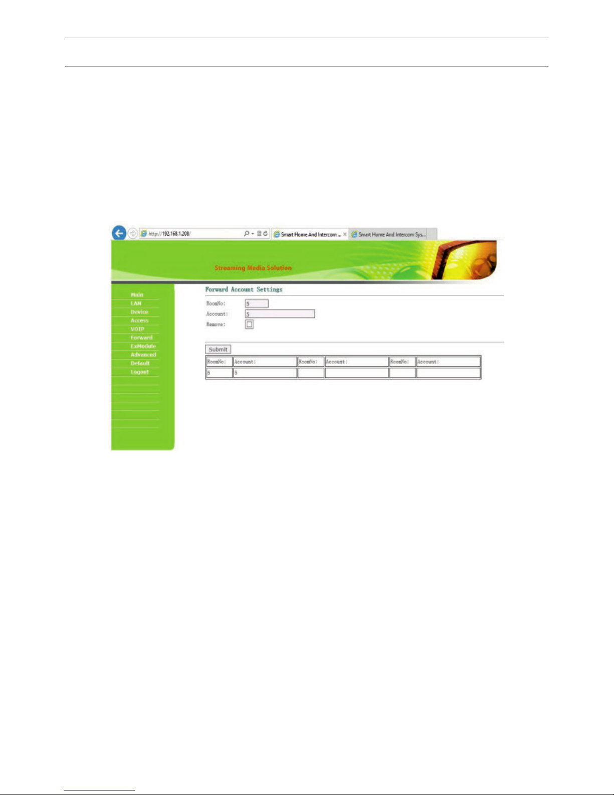
5. Making calls.
Select «Forward» to go to the next interface.
This section is used to forward calls received at the internal monitors when the
monitor is not available or if it is disabled on any given SIP-number.
1. “RoomNo” eld – enter the number of the apartment (oor + room) after
calling on which the call forwarding will occur.
For example, if the oor = 1 and the apartment = 1 you must enter the eld 0101.
2. “SIP-account” eld – enter the required SIP-number to which the call will come
from the outdoor panel when dialing the appropriate apartment.
Since 2015, the functionality of P2P SIP calls, which allows you to make calls to
SIP-clients within the local network without SIP PBX was added to the software
of outdoor panels. So that the outdoor panel can make a call to a SIP-client for
P2P networks, you need to enter the number of apartments (oor + room) in the
”RoomNo” eld, after calling on which the call forwarding will occur, and in the
“Account” eld the number like «sip:101@192.168.1.223 », where 101 – is desired
number to display, 192.168.1.223 – IP address SIP client (if using softphone – IP
address of the device on which the softphone is installed). The device on which
the call is forwarding must have a static IP address on the network.
Page 10

Getting streaming video via RTSP:
To display streaming video to the network recorder (NVR) or display it in the
video player, for example, VLC Media Player, it is necessary to address the
outdoor panel using the following initialization string: rtsp://address:8554/ch01,
where the address – is the IP-address of the current outdoor panel. The panel will
then request a username and password (the default username: admin, password:
123456). You can just enter this username and password into the initialization
string before the address, then the string of the receiving streaming video will
look like the following example:
rtsp://admin:123456@192.168.1.205:8554/ch01
SETTING THROUGH WEB INTERFACE
10
Page 11

CONNECTION SCHEME
GND
CAT 5e
C
O
M
NO
NC
.
.
Data 0
Data 1
GND
Connection by an external power supply (AV-01 and AV-01T)
CAT 5e
Data 0
Data 1
GND
+12V
GND
C
O
M
NO
N
C
.
.
CTRL
SGND
PGND
Connection by an uninterruptible power supply (AV-01 and AV-01T)
Black
Red
Yellow
Black
Red
Yellow
V
lock
lock
ONLY
NETWORK SWITCH
“EXIT“ BUTTON
OUTDOOR PANEL
V
LOCK
“EXIT“ CONTACT 1
“EXIT“ CONTACT 2
POWER SUPPLY
ONLY
“EXIT“ BUTTON
LOCK
“EXIT“ CONTACT 1
“EXIT“ CONTACT 2
OUTDOOR PANEL
POWER SUPPLY
NETWORK SWITCH
DELAY MODULE
ATTENTION:
THE LOCK OPENING TIME IS SET BY
ADJUSTING THE RESISTOR ON THE DELAY
MODULE BOARD SH-40.
V
+12 V
11
Page 12

GND
+18
CTRL
CAT 5e
C
O
M
NO
.
Data 0
Data 1
GND
GNDGND
V+V+
485+485+
485-485-
CAT 5e
COM
N
O
NC
GND
CONNECTION SCHEME
Connection by an uninterruptible power supply (AV-01 and AV-01T)
Black
Red
Yellow
ONLY
LOCK 1
LOCK 2
UPS DP/P
NETWORK SWITCH
OUTDOOR PANEL
V
“EXIT“ CONTACT 1
“EXIT“ CONTACT 2
“EXIT“ BUTTON
LOCK
POWER SUPPLY
OUTDOOR PANEL
V
LOCK
NETWORK SWITCH
+12 V
V
+12 V
12
Page 13

CONNECTION SCHEME
GNDGND
V+V+
485+485+
485-485-
CAT 5e
GND
C
O
M
NO
NC
.
.
CTRL
SGND
PGND
GND
CTRL
C
O
M
NO
.
GNDGND
V+V+
485+485+
485-485-
CAT 5e
Connection by an uninterruptible power supply (AV-01 and AV-01T)
v
Lock
Lock
Connection by an external power supply (AV-02 and AV-02FP)
V
NETWORK SWITCH
LOCK
+12 V
OUTDOOR PANEL
POWER SUPPLY
+12 V
+18 V
LOCK 1
LOCK 2
LOCK
V
OUTDOOR PANEL
NETWORK SWITCH
UPS DP/P
ATTENTION:
THE LOCK OPENING TIME
IS SET BY ADJUSTING THE
RESISTOR ON THE DELAY
MODULE BOARD SH-40.
13
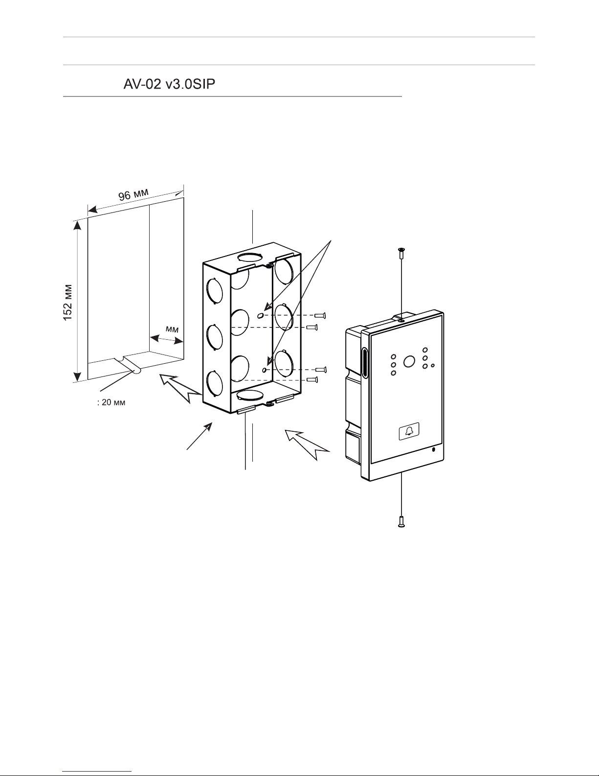
Page 14

MOUNTING
60
104
WIRES
SOCKET WATER-
PROOF COMPACTORS
MODEL
OUTDOOR PANEL
THE HOLES FOR
THE SCREWS
SCREWS
NICHE
BRACKET
HOLE FOR WATER
RUNOFF. PLEASE DO
NOT COVER DURING
MOUNTING.
PLATE WITH THE
NUMBER
PROTECTIVE
COVER
GUTTER
14
Page 15
MOUNTING
46
THE HOLES FOR
THE SCREWS
SCREWS
HOLE FOR WATER
RUNOFF. PLEASE DO
NOT COVER DURING
MOUNTING.
BRACKET
GUTTER
15
Page 16
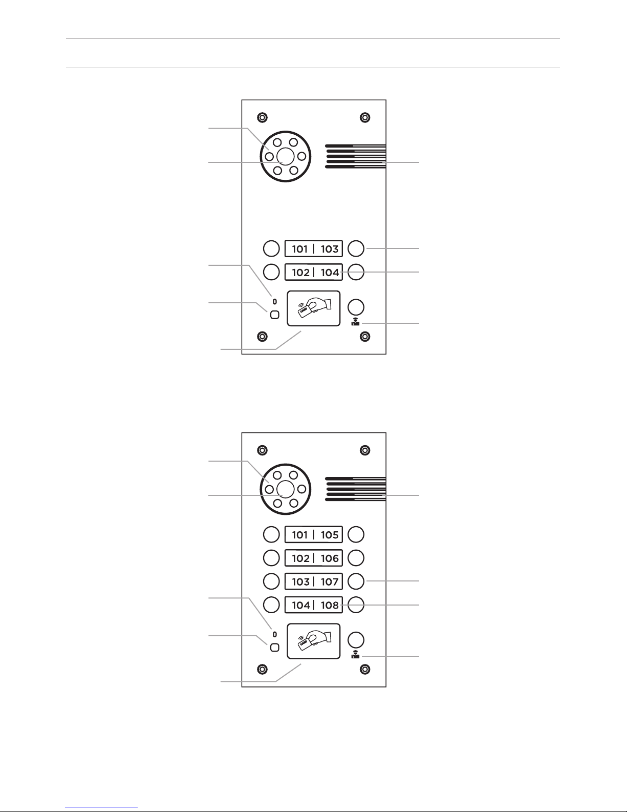
APPEARANCE
Model: BA-04 v3.0SIP
Model: BA-08 v3.0 SIP
Backlight
Backlight
Loudspeaker
Loudspeaker
Call button
Call button
Apartment number
Apartment number
Concierge button
Concierge button
Camera
Camera
Microphone
Microphone
Light sensor
Light sensor
Reader for
contactless
cards and keys
Reader for
contactless
cards and keys
16
Page 17
SPECIFICATIONS
Panel type
Individual
Screen
No
Camera
1/3”, adjustment of the camera direction
Angle
71° horizontal × 56° vertical
Resolution
800 TVL
Output video
D1 (704×576), H.264 Main Prole,
BaseLine Prole
Night backlight
6 LEDs
Light sensitivity
0,01 Lux
Protection class
IP65
Operating temperature
-40 – +65
0
С
Power consumption
5,5 W, in standby – 2,5 W
Power
+ 12 V
Body
Metal
Colors
Titanium-grey
Dimensions for installation
180×104×60 mm
Dimensions of panel
192×116×45 mm
Installation
Flush mount, wall mount
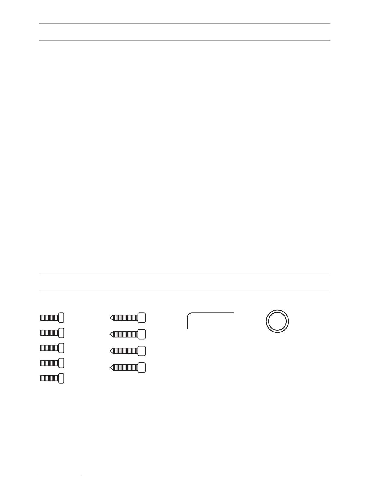
EQUIPMENT
Key
Sealing ring
Set screws
17
Page 18

SETTING THROUGH WEB INTERFACE
To congure the outdoor panel through the WEB-interface, you must connect to
it with a web browser on a PC. The panel must be connected to the same local
network segment as the PC from which you plan to make the settings. In the
Internet browser in the address bar, enter the IP-address of the outdoor panel,
and then enter the username and password. The username to enter the settings:
admin. The password required for entry must match the password for access to
the outdoor panel settings and is an installer’s password, default: 123456.
1. Network Settings.
Select «Network» to access the network conguration settings.
18
Page 19

SETTING THROUGH WEB INTERFACE
2. Device Settings.
Select «Device» to access the conguration of the logical address, the operating
mode and ringtones:
BuildNo: Specify the house number.
UnitNo: Specify the entrance number.
Floor: Specify the number of the oor.
RoomNo: Specify the number of the apartment.
No: Specify the outdoor panel serial number.
Panel mode: Set the operating mode «Unit Panel».
The number of the building, entrance, oor, and apartment must match the
address of the internal monitor, which will receive a call from this outdoor panel.
If you have several outdoor panels that have one logical address, then, enter a
value of 2, 3, 4, 5 and so on, until 9 in the “No” eld. If the logical addressing
of the outdoor panel corresponds to the addressing of the monitor, and the IP
addresses of the devices are in the same local network segment, the devices will
nd each other, and the call will occur correctly.
To make a call via the internal protocol to the internal monitor you must put “0”
in the “Floor” eld. Then when you call from the outdoor panel, the call comes to
the internal monitor.
19
Page 20
Registration for contactless cards via WEB-interface.
Enter in the “Master-card” number 0, and then click «Apply». Within 20 seconds,
bring the required fregistration master card to the area of the outdoor panel’s
reader – an alarm sounds “BEEP”, which means that the master-card has been
registered successfully. Now each user cards can be brought to the panel’s
reader. After each user card, a ”BEEP” will sound which indicates a successful
registration of the card.
The time between adding cards should not exceed 10 seconds.
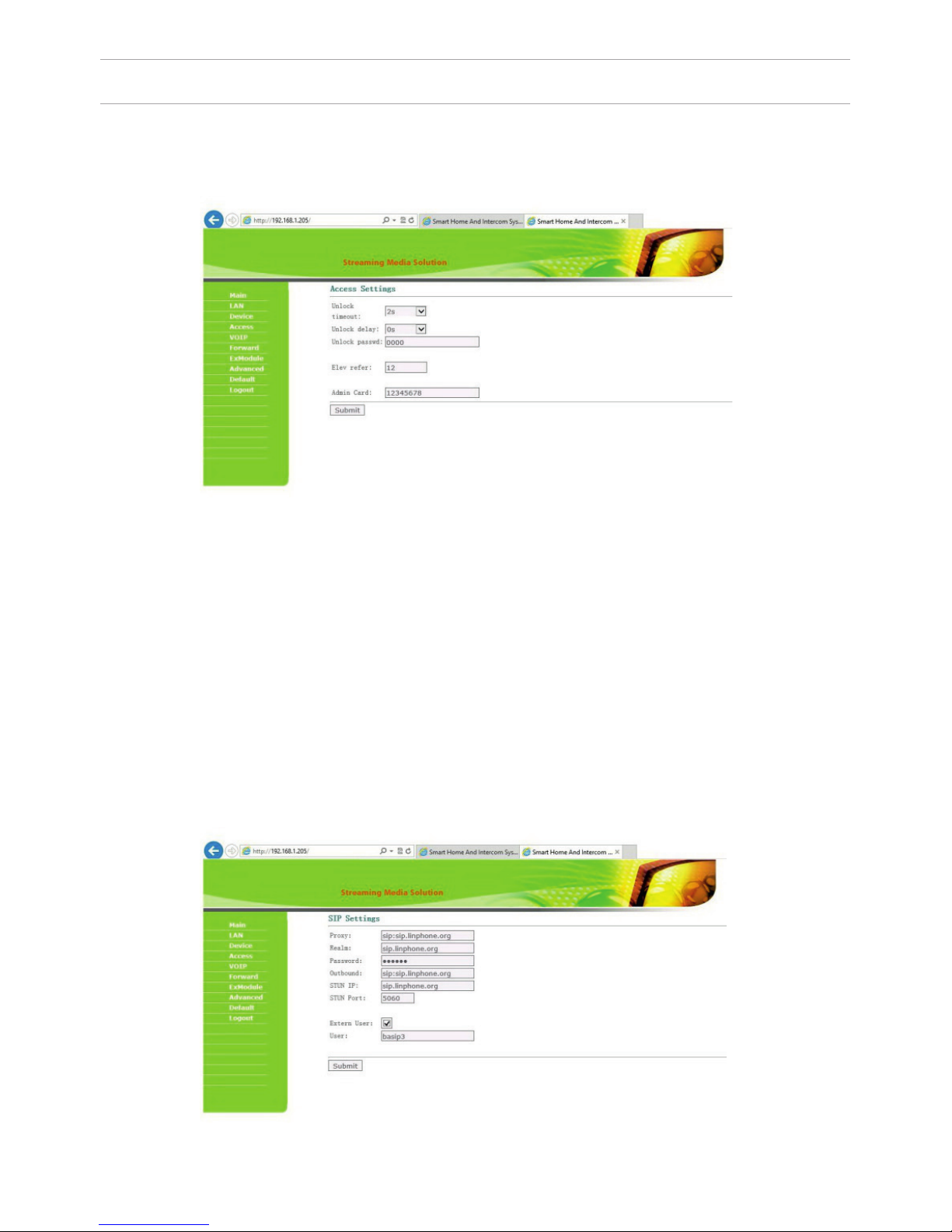
3. Access Settings.
Select «Access» to setting the opening time and the delay time of delay forthe
opening the door:
SETTING THROUGH WEB INTERFACE
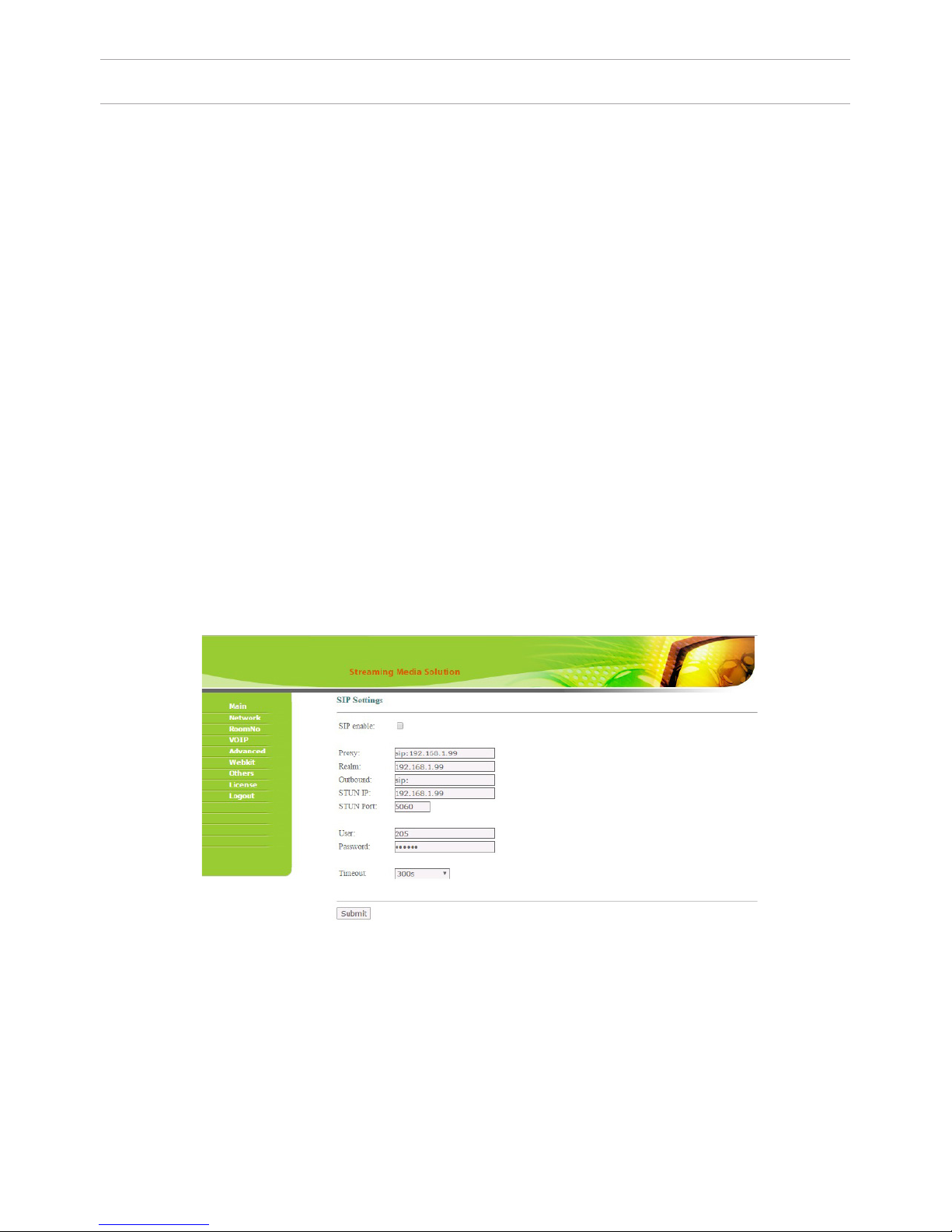
4. SIP settings.
Select «VOIP» for the transition to SIP account settings:
20
Page 21

SETTING THROUGH WEB INTERFACE
Proxy: SIP-server address can be specied as both the IP address and the
domain name.
For example: sip: 192.168.1.99, or sip: sip.linphone.org.
Domain: the domain address of the SIP-server is often the same as the IP address
of the SIP-server.
Password: Enter the password for the SIP-account (SIP-number).
Stun IP and Stun Port: indicates if this outdoor panel is mounted after NAT, for
example, a router.
Username: indicated directly SIP-account (SIP-number).
5. Making calls.
Select «Forward» to go to the next interface.
21
Page 22

SETTING THROUGH WEB INTERFACE
The numbers of call buttons look as follows:
0001
0002
0001
0002
0003
0004
0003
0004
0005
0006
0007
0008
Also, this section may be used for forwarding calls made by the SIP protocol
when there is no internal monitor, on any given SIP-account (SIP-number).
1. In the “Apartment” eld, enter the number of the call button after clicking
on which call forwarding will occur. The order of numbers of the call buttons is
shown in the gure above.
2. In the “SIP-account”, enter the required SIP-number to which the call will come
from the outdoor panel after pressing the corresponding button on it.
3. Click the “Apply” button to add values to the table.
So that the outdoor panel canould make a call to multiple devices
After pressing the call button on the panel, the panel can call up to 8 devices
simultaneously or in turn (switching to the call of the next number if the previous
number does not respond within 25 seconds), depending on the selected divert
mode in the tab “Device Settings”.
So that the outdoor panel canould make a call to multiple devices, you need
to enter the number of the apartment (oor + room) in the ”Room” eld, after
calling on which the call forwarding will occur, and in the “Account” eld the
numbers should be separated by a semicolon, like «sip:101@192.168.1.99 », where
101 – is the number you are calling, 192.168.1.99 – is the IP address of the SIP PBX
or the IP address of the called SIP client (when the call is made on P2P).
22
Page 23

SETTING THROUGH WEB INTERFACE
6. External Module settings (optional).
Select «ExModule» to go to the following interface:
7. Advanced settings.
Select “Advanced” to enter the following interface:
The address of the external VOIP-converter is set, which is transforms the SIP
protocol in the PSTN (Public Switched Telephone Network).
Quick Call: Call the Concierge monitor address with the help of the direct dial
button located on the front of the outdoor panel.
Set in this format: «sip: 1234@192.168.1.101», where 1234 – is a number of the
building that has been set in the concierge monitor and 192.168.1.101 – is the
IP-address of the concierge monitor.
Note: In multi apartment outdoor panels, BA-04 and BA-08, it is necessary to
put a check mark in front of the “Speed Dial” eld.
Otherwise these outdoor panels will not be able to make calls.
23
Page 24

SETTING THROUGH WEB INTERFACE
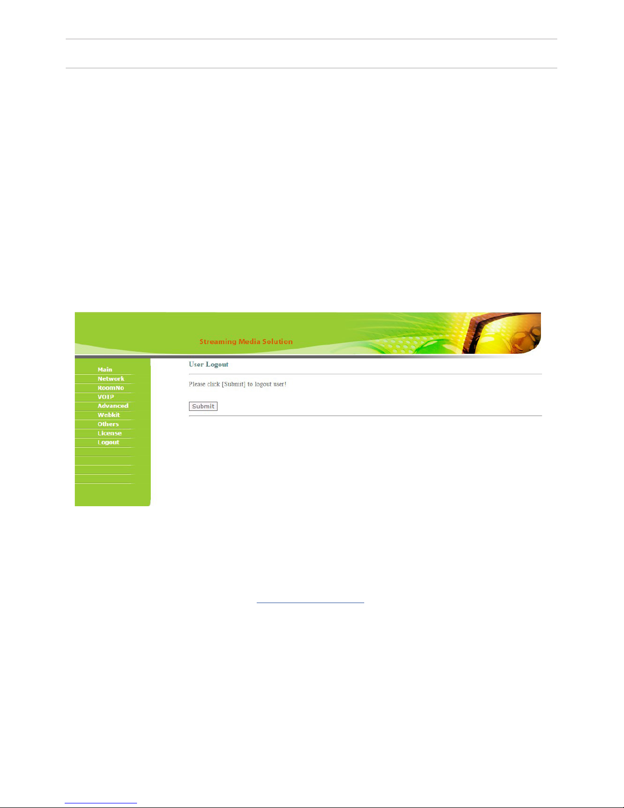
8. Sign Out.
Select «Sign Out» to enter the next interface:
Getting streaming video via RTSP:
To get display streaming video to the network recorder (NVR) or display it in the
video player, for example, VLC Media Player, enter the address the outdoor panel
using the following initialization string: rtsp://address:8554/ch01, where
address – is the IP-address of the current outdoor panel.
Next, the panel will request a username and password (the default use
name: admin, password: 123456).You can enter this username and
password into the initialization string before the address, and then the string of
receiving streaming video will look like the following example:
rtsp://admin:123456@192.168.1.205:8554/ch01
Click «Apply» button to exit the WEB-interface of the outdoor panel.
24
Page 25

CONNECTION SCHEME
Connection using an external power supply.
For connecting high power electric locks, you must use an additional power supply. The BA-04 and BA-08 connection diagram from the included power supply,
with an electromechanical lock is presented below:
Lock
Power supply
Network switch
“EXIT“ BUTTON
“EXIT“
COTAC T 2
BLACK
RED
YELLOW
v
v
“EXIT“
COTAC T 1
25
Page 26

CONNECTION SCHEME
26
Connection using an external power supply.
For connecting high power electric locks, you must use an additional power supply. The BA-04 and BA-08 connection diagram from the included power supply,
with an electromechanical lock is presented below:
Attention:
The opening time is set by adjusting the
resistor on the delay module board SH-40.
Delay module SH-40
“EXIT“ CONTACT 1
“EXIT“ CONTACT 2
“EXIT“ BUTTON
LOCK
POWER SUPPLY
V
V
Network switch
v
Page 27
CONNECTION SCHEME
27
Connection by a Uninterruptible Power Supply (UPS).
For connecting high power electric locks you must use an additional power
supply. The BA- 04 and BA-08 connection diagram from the uninterruptible
power supply, with an electromechanical or electromagnetic lock is presented
below:
Attention:
1. The lock opening time is set by
djusting the resistor on the
uninterruptible power supply board
UPS – DP/P.
2. The type of lock: electromechanical
or electromagnetic is set by the switch
on the uninterruptible power supply
board UPS – DP/P.
Uninterruptible power supply UPS – DP/P.
Network switch
BLACK
RED
YELLOW
“EXIT“ CONTACT 1
“EXIT“ CONTACT 2
“EXIT“ BUTTON
LOCK
V
V
V
Page 28

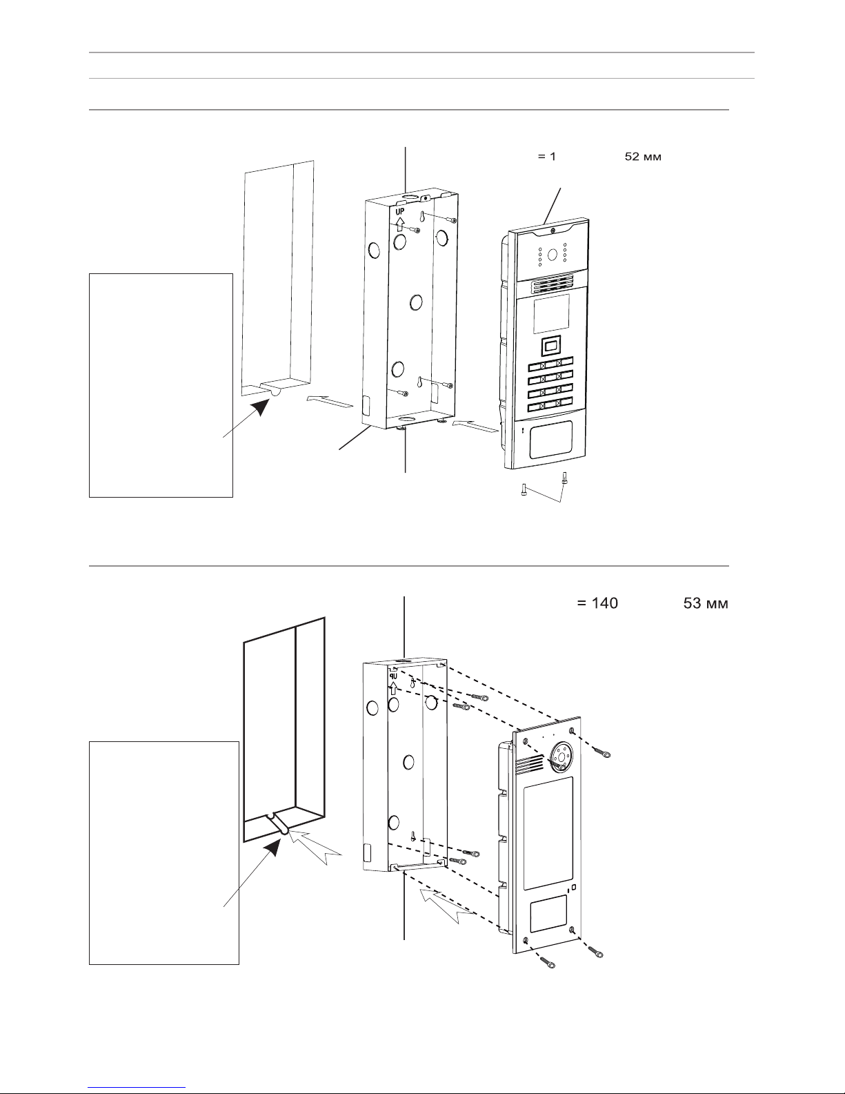
MOUNTING
28
Model: BA-04/08 v3.0 SIP
Wall mounting
Dimensions of the bracket
= 142 × 245 × 55 мм
Outdoor panel
Bracket
Screws
Attention:
The hole in the bottom of
the bracket is designed
to drain off water, do not
cover it.
It is also necessary to put
the discharge gutter at
the bottom of the niche,
which is used to drain the
water out.
Page 29

Multi apartment outdoor panels
1A2
B
7
G
8
H
3
4
5
6
9
0
*
#
C
D
E
F
I
J
APPEARANCE
BACKLIGHT
CAMERA
LOUDSPEAKER
BUTTONS
MICROPHONE
READER FOR
CONTACTLESS
CARDS AND KEYS
BACKLIGHT
CAMERA
LOUDSPEAKER
BUTTONS
MICROPHONE
LIGHT SENSOR
LIGHT SENSOR
LCD DISPLAY
BACKLIGHT
CAMERA
LOUDSPEAKER
LCD DISPLAY
BUTTONS
MICROPHONE
READER FOR
CONTACTLESS
CARDS AND KEYS
READER FOR
CONTACTLESS
CARDS AND KEYS
29
Page 30

MAIN FUNCTIONS
TECHNICAL PARAMETERS
1. The bright backlight of buttons and backlights for video cameras.
2. Graphic LCD display with backlight and support for the Rrussian language.
3. Color camera with night mode function.
4. Making calls to internal monitors, centralized remote concierge.
5. Multifunction possibilities of opening doors using access cards, contactless key
fobs, password access, opening with individual monitors and remote concierge.
Power supply: + 12 V
Operating temperature: -40 – +65 °C
Power consumption in standby mode: 3.6 W
Power consumption in operation mode: 6.5 W
The camera angle: ± 15° vertical, ± 20° horizontal
Video resolution: 700p
Protection class: IP65
Dimensions of the panels without bracket:
Model AA-01: 150×372×55 mm
Model AA-03: 155×375×47 mm
Model AA-05: 155×375×47 mm
Type of protocol output for ACS: Wiegand 26
30
Page 31

SETTING THROUGH WEB INTERFACE
To congure the outdoor panel through the WEB-interface, you must connect
to it with a web browser on a PC. The panel must be connected to the same
local network segment as the PC from which you plan to make the settings.
In the Internet browser in the address bar, enter the IP-address of the outdoor
panel, and then enter the username and password. The username to enter the
settings: admin. The password required for entry must match the password
for access to the outdoor panel settings and is an installer’s password, default:
123456.
1. Network Settings.
Select «Network» to access the network conguration settings:
2. Device Settings.
Select «Device» to access the conguration of the logical address, the operating
mode and ringtones:
31
Page 32
Registration for contactless cards via WEB-interface.
Enter in the “Master-card” number 0, and then click «Apply». Within 20 seconds,
bring the required registration master card to the area of the outdoor panel’s
reader – an alarm sounds and a “BEEP” means that the master-card has been
registered successfully. Next, the user cards can be brought to the panel’s reader.
After each user card , a ”BEEP” will sound which indicates a successful
registration of the card.
The time between adding of cards should not exceed 10 seconds.
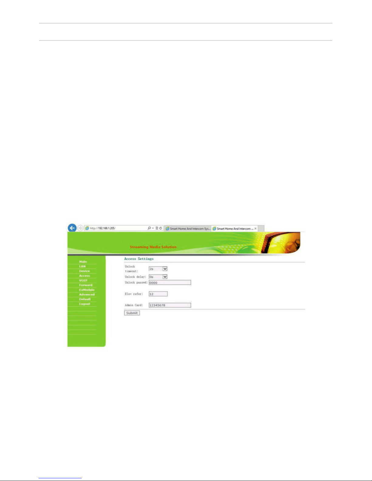
3. Access Settings.
Select «Access» for setting the opening time and the delay time for opening
the door:
SETTING THROUGH WEB INTERFACE
BuildNo: Specify the house number.
UnitNo: Specify the entrance number.
Floor: Specify the number of the oor.
RoomNo: Specify the number of the apartment.
No: Specify the outdoor panel serial number.
Panel mode: Set the operating mode «Unit Panel». The number of the building,
entrance, oor, and apartment must match the address of the internal monitor,
which will receive a call from this outdoor panel. If you have several outdoor
panels that have one Logical Adress , then enter a value of 2, 3, 4, 5 and so on,
until 9 in the “No” eld. If the logical adress of the outdoor panel corresponds to
the logical adress of the monitor, and the IP addresses of the devices are in the
same local network segment – the devices will nd each other, and the call will
occur correctly.
32
Page 33

4. SIP settings.
Select «VOIP» for the transition to SIP account settings:
Proxy: SIP-server address can be specied as both the IP address and the domain name. For example: sip: 192.168.1.99, or sip: sip.linphone.org.
Domain: domain address of SIP-server is often the same as the IP address of the
SIP-server.
Password: Enter the password for the SIP-account (SIP-number).
Stun IP and Stun Port: indicates if this outdoor panel is mounted after NAT, for
example, a router.
Username: indicated directly SIP-account (SIP-number).
5. Making calls.
Select «Forward» to go to the next interface.
SETTING THROUGH WEB INTERFACE
33
Page 34
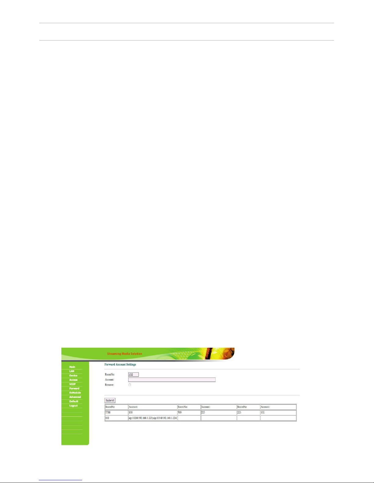
This section is used to forward calls received at the internal monitors when the
monitor is not available or it has been disabled on any given SIP-account (SIP-num
ber).
Apartment: enter the number of the apartment after calling on which the call for
-
warding will occur. The apartment number consists of 2 digits (number of the oor)
plus 2 digits (number of the apartments) in the settings of the internal monitor.
SIP-account: enter the required SIP-number that the call will come to from the
outdoor panel when dialing the appropriate apartment. For example: If number 5
was entered into the “Apartment” eld, and number 0005 in the “SIP-account” eld
when you type apartment #5 on the outdoor panel , the panel will make a call to
the SIP-account of “0005”. If number 101 was entered into the “Apartment” eld ,
and №12340575 was entered into the «SIP-account”, when you typed apartment
#101 on the outdoor panel, the panel will make a call to the SIP-account “12340575”.
Delete: Enter the check mark to remove forwarding to the SIP-number in the for
-
warding table, when dialing a certain apartment. For example: if number 234 was
entered into the “Apartment” eld, and there is a check mark in front of the “Delete”
eld, when you click «Conrm» the call forwarding to the specied SIP-number
when dialing the apartment #234 will be deleted. The corresponding line in the
forwarding table will also be deleted.
Note: the outdoor panel will forward a call to the specied SIP-account only if there
is no internal monitor corresponding to the number of this apartment. If there is an
internal monitor in this apartment, then it will be able to forward the call to speci
ed SIP-account by itself.
Since 2015, the functionality of P2P SIP calls, which allows you to make calls to
SIP-clients within the local network without SIP PBX was added to the software of
outdoor panels. So that outdoor panel can make a call to SIP-client for P2P net
-
works, you must enter the number of apartments (oor + room) in the “RoomNo”
eld, after calling on which the call forwarding will occur, and in the “Account” eld
the numbers like «sip:0001@192.168.1.223 », where 0001 – is the desired number to
display, 192.168.1.223 – IP address SIP client (if using softphone – IP address of the
device on which the softphone is installed). The device on which the call is forward
-
ing must have a static IP address on the network.
SETTING THROUGH WEB INTERFACE
34
Page 35

SETTING THROUGH WEB INTERFACE
In the settings of the device on which the call is coming, you must create a
SIP-account in where you specify the IP address of the outdoor panel as the SIP
server address, the desired display number from the preceding paragraph as a
login and leave the password eld empty. After pressing the call button on the
panel, the panel can call up to 8 devices simultaneously or in turn (switching to
the call of the next number if the previous number does not respond within 25
seconds), depending on the selected divert mode in the tab “Device Settings”.
So that the outdoor panel can make a call to multiple devices, enter the number
of the apartment (oor + room) in the ”Room” eld, after calling on which the
call forwarding will occur, and in the “Account” eld, separate the numbers with
a semicolon, like «sip:101@192.168.1.99 », where 101 – is the number you are
calling, 192.168.1.99 – IP address of the SIP PBX or IP address of the called SIP
client (when the call is made on P2P).
6. External Module settings (optional).
Select «ExModule» to go to the following interface:
The address of the external VOIP-converter is set, which is transforms the SIP
protocol in the PSTN (Public Switched Telephone Network).
35
Page 36

7. Advanced settings.
Select “Advanced” to enter the following interface:
Advertisement: set the advertising that will be displayed on the outdoor panel
screen when the panel goes into standby mode.
Time: set the time after which the advertising will begin to display.
Address: specify the address of the page with ads for standby mode.
Quick Call: the function of call instead of a concierge. If there is no concierge
monitor in the house, you can specify an address in this tab to which a call will
come. Set it in the format: «sip: 1234@192.168.1.101», where 1234 – is a number of
the building set in the monitor that will be used instead of the concierge monitor
and 192.168.1.101 – is the IP-address of the monitor.
SETTING THROUGH WEB INTERFACE
36
Page 37

SETTING THROUGH WEB INTERFACE
8. Sign Out.
Select «Sign Out» to enter the next interface:
Click the «Apply» button to exit the WEB-interface of the outdoor panel.
Getting streaming video via RTSP:
To display streaming video to the network recorder (NVR) or display it in the
video player, for example, VLC Media Player, enter the address of the outdoor
panel using the following initialization string: rtsp://address:8554/ch01, where
the address – is the IP-address of the current outdoor panel. Next, the panel
will request a username and password (the default username: admin, password:
123456). You can just enter this username and password into the initialization
string before the address, then the string of receiving streaming video will look
like the following example:
rtsp://admin:123456@192.168.1.205:8554/ch01
37
Page 38

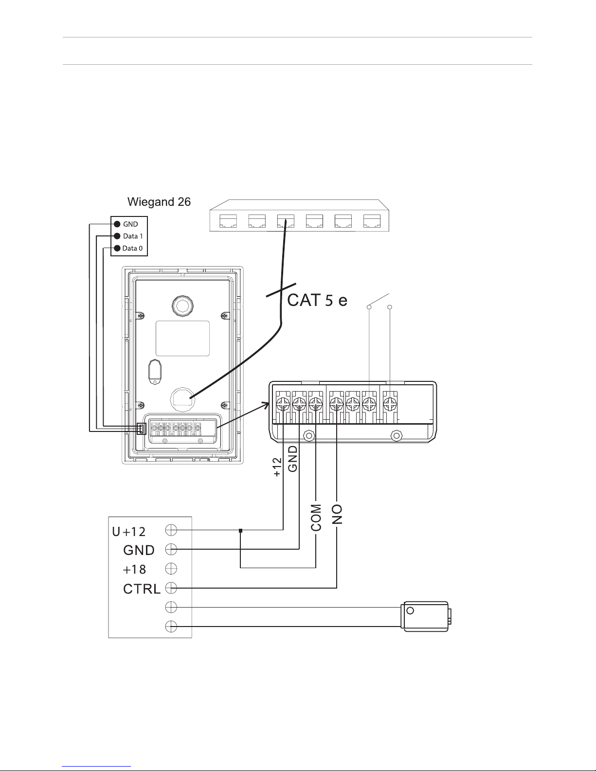
CONNECTION SCHEME
1.EXIT
2.GND
3.GND
4.DOOR
COM
RJ45
2.GND
3.NC
4.CTRL
5.LOCK
6.GND
UPS - DP/P
GND
485+
485
COM
Data 0
Data 1
GND
Wiegand 26
sensor
Yellow
Red
Black
button
Exit
button
Door
contact
LOCK
V
Attention:
1. The lock opening time is set by adjusting the resistor on uninterruptible power supply board
UPS – DP/P.
2. The type of lock: electromechanical or electromagnetic is set by the switch on the uninterruptible
power supply board UPS – DP/P.
38
V
V
1 2 3 4
Page 39
INSTALLATION
The hole in the
bottom of the bracket
is designed to drain
o water, do not
cover it.
It is also necessary to
make the discharge
gutter at the bottom
of the niche, which
will be used to drain
the water out.
355 ×
×
350 39 ×
×
The hole in the
bottom of the bracket
is designed to drain off
water, do not cover it.
It is also
necessary to make the
discharge gutter at the
bottom of the niche,
which will be used to
drain the water out.
Model: AA-01
W
All Mounting
diMensions of the brAcket
outdoor pAnel
niche
brAcket
screWs
Model:
AA-03
WAll Mounting
diMensions of the brAcket
screWs
niche
brAcket
39
Page 40

APPEARANCE
Internal monitors
Speakerphone
Photo frame
Concierge
View
Open
Power indicator
Message indicator
Security indicator
Alarm indicator
40
Page 41

MAIN FUNCTIONS
1. Touch screen made by SpeedRight technology.
2. Intuitive interface for management and conguration. Changeable wallpapers,
passwords for the user and installer, additional settings via the WEB-interface.
3. Video intercom between the internal monitors.
4. Support of 8 loops of home alarm, which can be connected to any security
sensors with NO or NC contacts.
5. Connect up to 16 IP cameras with ONVIF protocol support.
6. Support of 9 individual plus 9 multi apartment outdoor panels.
7. Integration with VOIP, PSTN, support of the SIP protocol.
8. Applications for smartphones and tablets (Android, iOS).
9. Connection of 8 additional monitors to the main one.
10. Recording of photo-, video- and audio le from the outdoor panels.
11. Receiving text and graphic messages from special software.
12. Answering machine with a record of video or audio messages.
13. Reproduction of audio, video and photos from the connected SD-card.
14. Management and connection of home automation modules.
15. Quick and easy connection via Ethernet and RJ45.
16. Use of protocol stack TCP/IP allows you to work in a standard local network
without conicting with other devices.
17. Operation in the picture frame mode or monitor to view IP cameras.
18. Simple software update via the SD-card or network.
TECHNICAL PARAMETERS
1. Power supply: +12 V
2. Operating temperature: 0 - 55 °C
3. Power consumption in operating mode: 6 W
4. Power consumption in standby mode: 2.5 W
5. Talking mode: speakerphone «Hands-Free»
6. Conversation time between internal monitors: up to 5 minutes
7. Conversation time with individual outdoor panel: 4 minutes
8. Conversation time with multi apartment outdoor panel: 4 minutes
9. The minimum required channel width in the Ethernet network: 1.5 Mbit
10. Storage temperature: -10 - +65 °C
41
Page 42

CONFIGURATION VIA THE MONITOR’S
GRAPHIC INTERFACE
Main screen: Sequrity, VOIP, Smart, Service, Contacts, Media Player.
Status icons: Service, the SIP status, Voice recorder, Security, Mute.
The functionality of status icons:
1. Services: Order of services, access to the specied WEB-page, receiving news.
Messages and status of the local network.
2. SIP Status: lights when connected successfully to the SIP server. 3. Voice
recorder: quick access to voice records.
4. Security: blinks during when turning on the security mode, and glows during
security mode. Time of turning on security mode: 100 seconds.
5. Mute: used to activate “Do Not Disturb”.
6. Messages: quick access to the received messages menu.
7. Network Status: displays the current status of the LAN connection.
42
Page 43
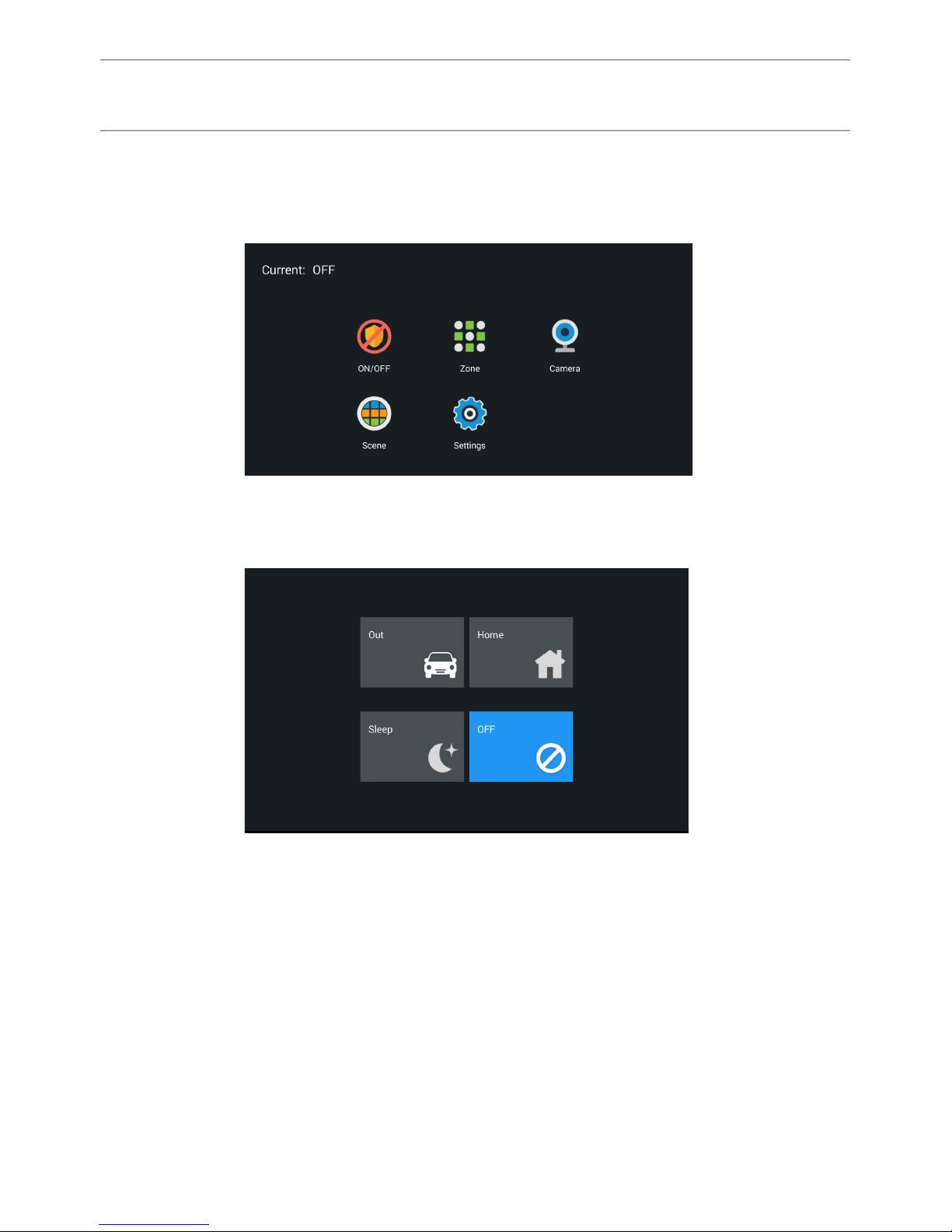
1. Security.
Depending on the model of the internal monitor, can be from 4 to 8 loops
security alarm. Click the “Security” to enter the interface:
Alarms can be set in different modes: “Home”, “Out” and “Sleep”.
1.1 Switching security modes.
1.1.1 Switching security on.
Press the “At home”, “Outside” or “Sleep” mode button to activate the
appropriate protection. During arming, a predetermined time from 0 to 300
seconds, the tone of “beep-beep” will sound, and then the monitor will arm.
1.1.2 Switching the security off.
To stop the armed mode, you must press the “Off” button, then the alarm will be
disabled.
43
CONFIGURATION VIA THE MONITOR’S
GRAPHIC INTERFACE
Page 44

2. IP-cameras.
Click the “Camera IP» button to enter the viewing interface IP-based cameras:
Press the “Right” or “Left” button to select the desired camera. Then, press the
camera button to view it and pause button to stop.
3. Communication.
Click “Link” to enter the following interface, consisting of the “Call”, “Browse”,
“Record”, “Address”, “the SIP” and “Settings”.
44
CONFIGURATION VIA THE MONITOR’S
GRAPHIC INTERFACE
Page 45

3.1 Wieving outdoor panels.
Push the “Monitor“ button to go to the following interfase.
By clicking on the word “Door01“ you can switch between personal panel and
milti-apartment panel. Use the “Right” and “Left” buttons to choose the number
of multi-apartment and individual panels.To view the selected panel, press the
button “Watch”, and to complete - the button “Pause”. To open the door while
viewing the selected panel, press the “Opening the lock” button.
3.2 Calls.
3.2.1 Calls between internal monitors.
Enter from 1 to 4 digits of the house and click on “Building”, then enter the
2 digits of the front door and press the “door”, then enter 1 to 4 digits of the
apartment and press the call button. To delete a digit entered incorrectly, use the
“Delete” button.
45
CONFIGURATION VIA THE MONITOR’S
GRAPHIC INTERFACE
Page 46

3.2.2 Intercom.
The system supports the function of the video intercom, through cameras that
are built into the internal monitors. In order to transmit your image to another
person, it is necessaryyou need to turn on a built-in camera.
Answering machine: When the outdoor panel’s call button is pressed, the
monitor, in addition to automatic recording of images, can also record audio and
video. For this, you must turn on the appropriate buttons in the given settings.
Recording audio and video les is made only on a removable SD-card.
To access additional internal monitors or call the main monitor, select from the
list (primary, Add.1 - Add.9) and press the call button.
3.2.3 Calls to SIP-numbers and mobile phone numbers.
To make VoIP calls, simply you dial the SIP-address to which you want to make a
call. To make a call on a cell phone is necessary to dial a mobile number in international format with “+” digit in the front of the number.
3.2.4 To answer the incoming call.
During an incoming call the following interface will appear:
Press the “Answer” button to answer the call, and press the “End” to end the call.
Press the “Open lock” button to open the door. W During a conversation with the
visitor, press the “Photo” button to save the current image in the internal memory of the monitor. To record a video, click the “Video” and press the “microphone” button to disable the built-in microphone.
46
CONFIGURATION VIA THE MONITOR’S
GRAPHIC INTERFACE
Page 47

SETTING THROUGH WEB INTERFACE
1. Network Settings.
Select «Network» to access the network conguration settings:
2. Device Settings.
Select «Device» to access the conguration of the logical address, the operating
mode and ringtones.
47
Page 48
SETTING THROUGH WEB INTERFACE
3. SIP settings.
Select «VOIP» for the transition to SIP account settings:
Building (House): specify the house number which must consist of numbers with
values from 1 to 9999.
Entrance: specify the entrance number which should be set within the range from
1 to 99.
Floor: specify the oor number within the range of 0 to 99.
Apartment: specify the apartment number within the range of 0 to 99.
Note: The building, entrance, oor, and apartment number must match the address
of the internal monitor, which will receive a call from the given outdoor panel. For
example: If the outdoor panel has set the values like “Building” = 1, “Entrance” =
1, “Floor” = 0, “Apartment” = 5, it will make the call on the internal monitor which
has exactly the same values address settings in “Building”, “Entrance”, “Floor” and
“Apartment” elds.
Panel number: the serial number of individual outdoor panel, which is set within
the range from 1 to 9. The system password: specify a password for access to the
panel settings which is also an installer password, which is the default 123456.
Ringtone: select a call melody that will sound from the panel’s speaker as “Call
conrmation melody” at the time of making a call to the internal monitor or
SIP-client.
Proxy: SIP-server address can be specied as both the IP address and the domain
name. For example: sip: 192.168.1.99, or sip: sip.linphone.org.
Domain: domain address of SIP-server is often the same as the IP address of the
SIP-server.
Password: Enter the password for the SIP-account (SIP-number).
Stun IP and Stun Port: indicates if this monitor is mounted after NAT, for example,
a router.
Username: indicated directly SIP-account (SIP-number).
48
Page 49

SETTING THROUGH WEB INTERFACE
7. Advanced settings.
Select “Advanced” to enter the following interface:
Forwarding: Enable or disable forwarding of incoming calls to a specied
SIP-address (SIP-number). When this option is enabled, the internal monitor will
simultaneously make a call to a given SIP-address when it receives any incoming
call. You can set two SIP-addresses.
5. Adding IP cameras.
Connect your computer to the same subnet as the internal monitor, then in the
browser enter its IP-address (http: // IP-address of the internal monitor), to enter
the set interface and add the IP cameras. Enter the user name and password (the
default user name is «user», and the password is 1234). Then click the tab “Instal-
lation IPC», to congure the IP cameras:
49
Page 50
SETTING THROUGH WEB INTERFACE
6. Sign Out.
Select «Sign Out» to enter the next interface:
The ONVIF string – should appear automatically as RTSP stream initialization
string. If it does not appear, then the IP camera does not have a ONVIF, or its
ONVIF specication does not meet the standards. In this case, the parameters
must be lled manually, but you do not need to ll in the ONVIF eld.
Name: enter the name of the IP camera.
User: enter the user name for access to the IP camera.
Password: enter the user password to access the IP camera.
CHI: you must enter the IP address of the camera and its RTSP initialization
string.
Click «Apply» button to exit the WEB-interface of the internal monitor.
You can nd more detailed instructions on setting up the internal monitor
functions on our website in the download section.
50
Page 51

CONNECTION SCHEME
Connection of the sockets on the back of the internal monitor.
V+
NC1
NC2
NC3
NC4
NC5
NC6
NC7
NC8
GND
V1+GND
+12VGND485+485-
UTP CAT 5e
SH-61
51
Page 52

APPEARANCE
Build-in camera
(optionally)
Handset
Power indicator
View button
Door release
button
Model AM-01 v3.
52
Page 53

MAIN FUNCTIONS
TECHNICAL PARAMETERS
1. Touch screen.
2. Photo and video recording of visitors.
3. The connection between the internal monitors and outdoor panels.
4. Viewing all authorized outdoor panels and lock control.
1. 9” TFT screen with touch control
2. Dimensions: 303×195×29.5 mm
3. Mounting type: desktop
4. Power supply: + 12 V
5. Operating temperature: 0 - 55 °C
6. Power consumption in operating mode: 6.7 W
7. Power consumption in standby mode: 4.7 W
8. Conversation time: 4 minutes
9. Viewing time: 30 seconds
53
Page 54

Main screen
Communication: enter the calls menu
View: enter the viewing outdoor panels menu.
Applications: enter the additional functions menu
System settings: access to the setup menu
Call history: view the call history
Alarm records: view alarm messages
54
CONFIGURATION VIA THE MONITOR’S
GRAPHIC INTERFACE
Page 55
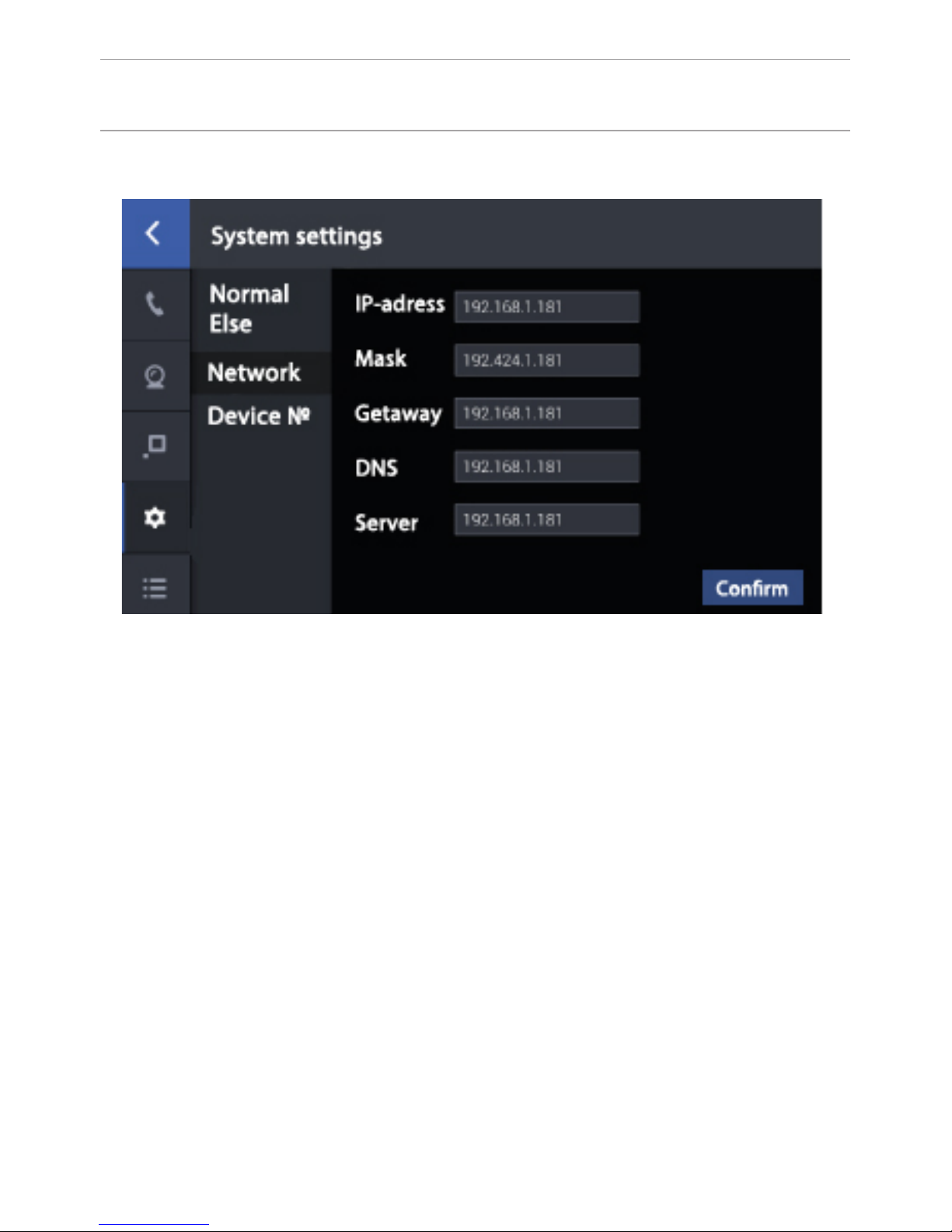
IP addresses may not be identical withinin the same subnet. Network default:
255.255.255.000. Usually it is not necessary to change its values. To change
the values of the required parameters, click, enter the required values, and click
“Conrm”.
1. Network settings.
55
CONFIGURATION VIA THE MONITOR’S
GRAPHIC INTERFACE
Page 56

2. Thelogical addresssettings.
1. In the “Building” eld you must enter the logical adress of the concierge
monitor. The IP-Address of the building must correspond to the building logical
adress in the settings of the devices used.
2. Enter 0 in the “Main” eld in the main concierge monitor. For additional
monitors, enter values from 1 to 8.
3. The “Sync” eld should match on the main and additional monitors. Enter
6 digits in this eld that must be identical on the main concierge monitor and
additional monitors. This eld must be lled in order to get calls on the monitors
simultaneously.
4. Conguring the logical adress.
Click «Address» to enter the logical adress conguration interface.
Note: If you do not program the «Call instead concierge» on internal monitors
and multi apartment outdoor panels, this button will call the concierge monitors
with the building number from 1 to 5. So that to internal monitors and outdoor
panels can call the concierge monitor which has the same house number, you
must program the concierge call button in the web interface settings of internal
monitors and outdoor panels!
56
CONFIGURATION VIA THE MONITOR’S
GRAPHIC INTERFACE
Page 57

NOTES
Technical maintenance of devices
1. Keep the devices clean and use a dry cloth for cleaning soft dust.
2. When cleaning the devices, please turn off the power.
3. If the device is very contaminated and cannot be cleaned with a dry cloth,
please use a soft cloth dampened with diluted detergent, and then wipe it dry
with a cloth.
Do not use petrol, solvents or organic solutions for cleaning as, they may damage
the body and change the device color.
Note the following:
1. Carefully read the operating instructions. Be sure to save themit for future use.
2. Use only the supplied power supply units, and also make sure your network
meets the listed power specications intended for the power supply. If you are not
sure – consult your dealer or your local power company.
3. Do not apply strong shocks and drop of devices. If the device has been damaged, immediately contact an authorized service center.
4. Do not operate the device in aggressive environments. The location must be
selected away from electromagnetic elds. In order to avoid electromagnetic interference – do not place the device near high-power power supplies and power
cables.
5. Do not install or operate the device in the direct sunlight, heavy rain, high temperatures, high humidity or dust sources.
6. Do not use the outdoor panels and monitors in areas of strong backlight or in
direct sunlight.
7. Turn off the power during installation.
8. Do not disassemble the device by yourself. If repairs are required, please contact your dealer or authorized service center.
57
Page 58

1. The warranty card must indicate the name of the model, serial number,
purchase date, name of the seller, seal of the trade organization and the
customer’s signature. Delivery to the warranty repair is the responsibility of the
buyer.
3. Warranty repairs will be carried out only during the warranty period specied
in the warranty card.
4. The service center is committed to do everything possible to carry out the
repair warranty products, up to 24 working days. The period spent on the
restoration of product functionality is added to the warranty period.
Terms of warranty
Breach of terms of warranty
1. This warranty is invalid if the serial number on the product is altered, deleted,
removed or made illegible.
2. The warranty is invalid in case of any changes and adaptations in order to
improve or expand the scope of device usage listed in the instruction manual.
3. The guarantee becomes invalid when the product has been used for other
purposes or not in accordance with the manual for operation and maintenance.
4. The warranty becomes invalid in case of accidental or intentional contact with
foreign objects, substances, liquids, vapors, corrosive gases, insects in the
internal or external part of the product.
5. The warranty becomes invalid in case of a the wrong connection of the
product with other systems, or incorrect mounting and installation.
6. The warranty does not cover defects and damages of any system in which the
product has been implemented or in conjunction with which has been used.
7. The guarantee is invalid if there is mechanical damages on the product, splits,
dents, cracks, traces of tampering, etc.
8. The guarantee does not apply to the product, if there is damage caused by the
mismatch of the State standards of supply parameters, telecommunication, cable
networks and other similar external factors.
9. This warranty does not apply to products which have internal or external
damage due to external factors such as natural disasters, res, oods, lightning,
thunder, voltage uctuations and other causes beyond the control of the
manufacturer.
10. The guarantee becomes invalid when you try to repair products by
unauthorized service centers or other individuals and organizations that do not
have the legal authority to repair these products.
11. The warranty does not include accessories (batteries, an external power
supply, connecting cables), as well as components and parts of the product
which are out of order as a result of natural wear.
Page 59

The warranty card number _______________
The warranty period of the product - 24 (twenty- four) months from the date of
sale.
- Transportation of the product must be in its original packaging or one supplied
by the seller.
- The product is accepted in warranty repair only with a properly lled warranty
card and the presence of intact stickers or labels.
- The product is accepted for examination in accordance with the cases provided
by law, only in the original packaging, in a full complete set, and its appearance
corresponding to the new equipment and presence of all relevant properly lled
documents.
- This warranty is in addition to the constitutional and other consumer rights and
in no way restricts them.
With following stated terms of warranty is familiar, functional test was performed
in my presence:
Customer signature:
_____________________________________________________
The model name
Serial number
Full name of the seller
________________________
________________________
________________________
 Loading...