


BEST IDEAS FOR IP
INTERCOM SOLUTIONS

2
Note
For the correct installation, follow the instructions. If you have any difficulty with
installation and operation, please contact your dealer for advice. The technical
parameters and specifications mentioned here may vary slightly from those
stated in the instructions of the devices. This is our company conducts constant
upgrading and improvement of the functionality to improve the characteristics
of current devices.

CONTENT
Individual outdoor panels
Appearance ...............................................................................................................
Main functions ..........................................................................................................
Technical parameters ............................................................................................
Equipment .................................................................................................................
Setting through WEB interface .........................................................................
Connection scheme ...............................................................................................
Mounting ....................................................................................................................
Multi apartment outdoor panels
Appearance ...............................................................................................................
Connection ................................................................................................................
Equipment .................................................................................................................
Setting through WEB interface .........................................................................
Connection scheme ...............................................................................................
Mounting ....................................................................................................................
Internal monitors
Appearance ...............................................................................................................
Main functions ..........................................................................................................
Technical parameters ............................................................................................
Setting through WEB interface .........................................................................
Connection scheme ...............................................................................................
Installation .................................................................................................................
Concierge monitor
Appearance ...............................................................................................................
Main functions ..........................................................................................................
Technical parameters .............................................................................................
Conguration via the monitor’s graphic interface ......................................
Setting through WEB interface .........................................................................
Connection scheme ................................................................................................
Appearance ...............................................................................................................
Main functions ..........................................................................................................
Technical parameters ............................................................................................
Conguration via the monitor’s graphic interface ......................................
Notes ............................................................................................................................
3
4
4
5
6
6
11
14
16
17
17
18
25
28
29
30
30
31
38
39
40
41
41
42
47
51
52
53
53
54
57
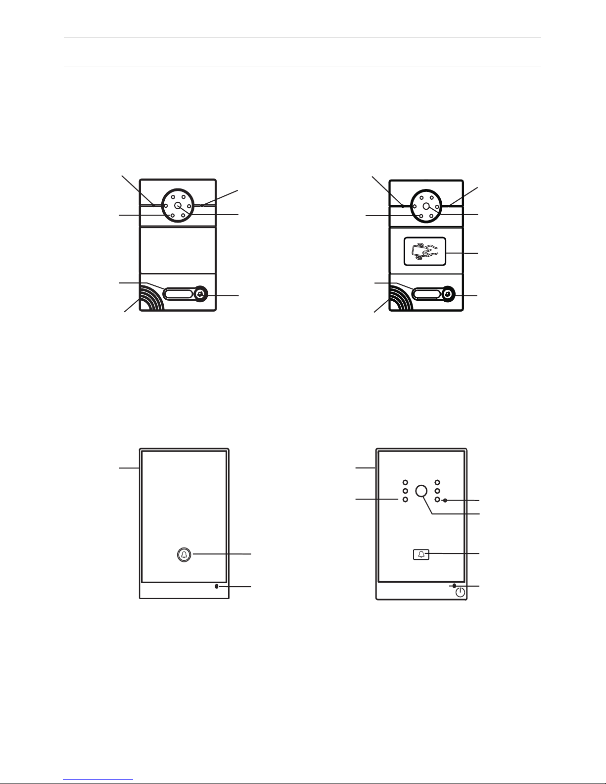
APPEARANCE
Model AV-01 (v2.0 and v3.0 SIP) Model AV-01T (v2.0 and v3.0 SIP)
Model: AV-02 v3.0 SIP
LIGHT SENSOR
MICROPHONE
CAMERABACKLIGHT
RING BUTTON
LOUDSPEAKER
RING BUTTON
RING BUTTON
CAMERA
CAMERA
LIGHT SENSOR
LIGHT SENSOR
BACKLIGHT
READER FOR
CONTACTLESS
CARDS
IN A FIRE
PRESS TO COMMUNICATE
WITH A DISPATCHER
Model: AV-02FP
4
LIGHT SENSOR LIGHT SENSOR
BACKLIGHT
SIGN WITH THE
NUMBER
LOUDSPEAKER
SIGN WITH THE
NUMBER
MICROPHONE
MICROPHONE
RING BUTTON
MICROPHONE

MAIN FUNCTIONS
Interface
WEB-interface
Lock opening
By card, with the monitor
Access control
Reader for contactless cards
EM-Marin or MIFARE
Integration with ACS
Output WIEGAND-26
Buttons for quick dialing
1 call button
Number of ringtones
4 polyphonic ringtones
Authentication
WEB-interface
Talking mode
Double-sided
Talking time
Up to 240 seconds
Additional functions
SIP P2P
Place for the signature near the call
button
Stores up to 10,000 cards
Recording cards available through software
or using master card
TECHNICAL PARAMETERS
Panel type
Individual
Screen
No
Camera
1/3”, adjustment of the camera
direction
Angle
71° horizontal × 56° vertical
Resolution
800 TVL
Output video
D1 (704×576), H.264 Main Prole,
BaseLine Prole
Night backlight
6 LEDs
Light sensitivity
0,01 lux
Protection class
IP65
Operating temperature
-40 – +65 °C
Power consumption
5,5 W, in standby – 2,5 W
Power
+ 12 V
Body
Metal
Colors
Titanium-grey
Dimensions for installation
180×104×60 mm
Dimensions of panel
192×116×45 мм
Installation
Flush mount, wall mount
5
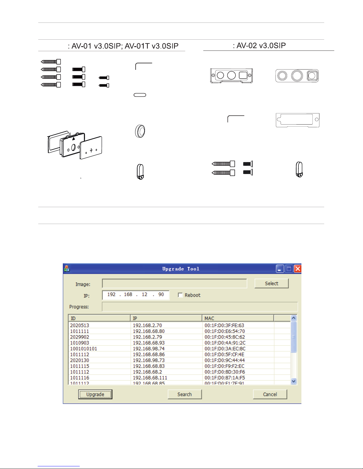
EQUIPMENT
SETTING THROUGH WEB INTERFACE
Search for the IP-address of the outdoor panel.
After you have connected the outdoor panel in the same local area network as
your computer, run the program «Upgrade Tool» to determine the IP-address of
the outdoor panel.
Press the “Search” button and the program window will display the IP-address
of the outdoor panel and any other devices BAS-IP, which are connected to the
local network.
Model
Model
MOUNTING
SCREWS
KEY
PROTECTIVE
COVER
WATERPROOF CAP
AND PROTECTIVE CABLE COVER 1
PROTECTIVE
CABLE COVER 2
PROTECTIVE
CABLE COVER 3
KEY
PROTECTIVE
CABLE COVER 2
MOUNTING
SCREWS
PROTECTIVE
CABLE COVER 3
WATERPROOF CAP
AND PROTECTIVE
CABLE COVER 1
PROTECTIVE CABLE
COVER 1

To congure the outdoor panel through the WEB-interface, you must connect to
it sing a web browser on a PC. The panel must be
connected to the same local network segment as the PC from which you plan
to make the settings. In the Internet browser in the address bar enter the IP-address of the outdoor panel, and then enter your username and password. The
username to enter the settings: admin. The password required for entry must
match the password for access to the outdoor panel settings and is an installer’s
password, default: 123456.
1. Network Settings.
Select «Network» to access the network conguration settings:
7
SETTING THROUGH WEB INTERFACE
2. Device Settings.
Select «Device» to access the conguration of the Logical address, the operat-
ing mode and ringtones:

SETTING THROUGH WEB INTERFACE
BuildNo: Specify the house number.
UnitNo: Specify the entrance number.
Floor: Specify the number of the oor.
RoomNo: Specify the number of the apartment.
No: Specify the outdoor panel serial number.
Panel mode: Set the operating mode «Personal Panel». The number of the
building, entrance, oor, and apartment must match the address of the internal
monitor, which will receive a call from this outdoor panel. If you have several
outdoor panels that have one logical address, then in the “No” eld, enter a value
of 2, 3, 4, 5 and so on, until 9. If the logical address of the outdoor panel
corresponds to the logical address of the monitor, and the IP addresses of
the devices are in the same network segment – the devices will nd each other,
and the call will occur correctly.
3. Registration of contactless cards via WEB-interface.
Enter in the “Master-card” number 0, and then click “Apply”. Within 20 seconds,
bring the required registration master card to the area of the outdoor panel’s
reader – an alarm sounds ”BEEP”, which means that the master-card has been
registered successfully. Now, each user card can be brought to the panel’s reader.
After each user card, ”BEEP” will sound which indicates a successful registration
of the card. The time between adding cards should not exceed 10 seconds.
4. SIP settings.
Select «VOIP» for the transition to SIP account settings:
8
SETTING THROUGH WEB INTERFACE
Proxy: SIP-server address. It can be specied as the IP address and the domain
name. For example: sip: 192.168.1.99, or sip: sip.linphone.org.
Domain: The domain address of the SIP-server is often the same as the IP
address of the SIP-server. Password: Enter the password for the SIP-account
(SIP-number).
Stun IP and Stun Port: indicates if this outdoor panel is mounted after NAT, for
example, a router. Username: indicated directly SIP-account (SIP-number).
9
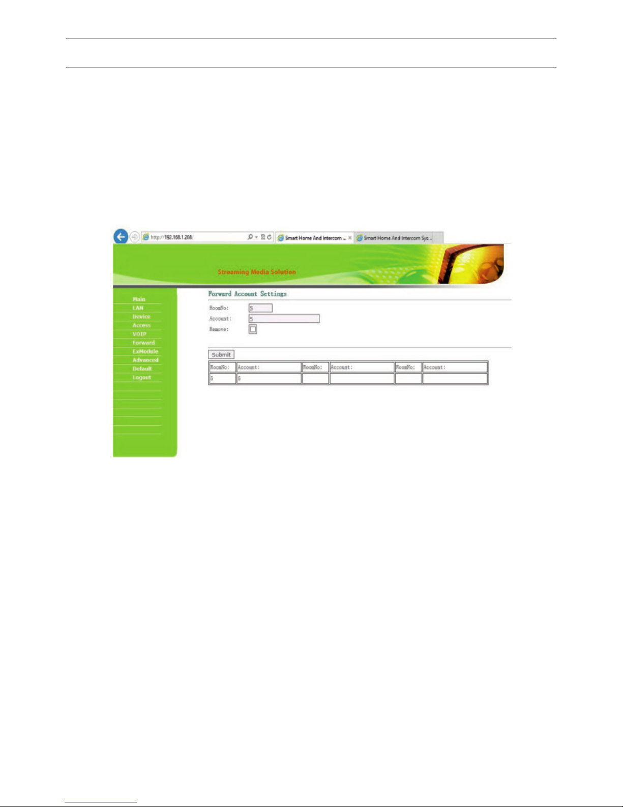
5. Making calls.
Select «Forward» to go to the next interface.
This section is used to forward calls received at the internal monitors when the
monitor is not available or if it is disabled on any given SIP-number.
1. “RoomNo” eld – enter the number of the apartment (oor + room) after
calling on which the call forwarding will occur.
For example, if the oor = 1 and the apartment = 1 you must enter the eld 0101.
2. “SIP-account” eld – enter the required SIP-number to which the call will come
from the outdoor panel when dialing the appropriate apartment.
Since 2015, the functionality of P2P SIP calls, which allows you to make calls to
SIP-clients within the local network without SIP PBX was added to the software
of outdoor panels. So that the outdoor panel can make a call to a SIP-client for
P2P networks, you need to enter the number of apartments (oor + room) in the
”RoomNo” eld, after calling on which the call forwarding will occur, and in the
“Account” eld the number like «sip:101@192.168.1.223 », where 101 – is desired
number to display, 192.168.1.223 – IP address SIP client (if using softphone – IP
address of the device on which the softphone is installed). The device on which
the call is forwarding must have a static IP address on the network.

Getting streaming video via RTSP:
To display streaming video to the network recorder (NVR) or display it in the
video player, for example, VLC Media Player, it is necessary to address the
outdoor panel using the following initialization string: rtsp://address:8554/ch01,
where the address – is the IP-address of the current outdoor panel. The panel will
then request a username and password (the default username: admin, password:
123456). You can just enter this username and password into the initialization
string before the address, then the string of the receiving streaming video will
look like the following example:
rtsp://admin:123456@192.168.1.205:8554/ch01
SETTING THROUGH WEB INTERFACE
10

CONNECTION SCHEME
GND
CAT 5e
C
O
M
NO
NC
.
.
Data 0
Data 1
GND
Connection by an external power supply (AV-01 and AV-01T)
CAT 5e
Data 0
Data 1
GND
+12V
GND
C
O
M
NO
N
C
.
.
CTRL
SGND
PGND
Connection by an uninterruptible power supply (AV-01 and AV-01T)
Black
Red
Yellow
Black
Red
Yellow
V
lock
lock
ONLY
NETWORK SWITCH
“EXIT“ BUTTON
OUTDOOR PANEL
V
LOCK
“EXIT“ CONTACT 1
“EXIT“ CONTACT 2
POWER SUPPLY
ONLY
“EXIT“ BUTTON
LOCK
“EXIT“ CONTACT 1
“EXIT“ CONTACT 2
OUTDOOR PANEL
POWER SUPPLY
NETWORK SWITCH
DELAY MODULE
ATTENTION:
THE LOCK OPENING TIME IS SET BY
ADJUSTING THE RESISTOR ON THE DELAY
MODULE BOARD SH-40.
V
+12 V
11

GND
+18
CTRL
CAT 5e
C
O
M
NO
.
Data 0
Data 1
GND
GNDGND
V+V+
485+485+
485-485-
CAT 5e
COM
N
O
NC
GND
CONNECTION SCHEME
Connection by an uninterruptible power supply (AV-01 and AV-01T)
Black
Red
Yellow
ONLY
LOCK 1
LOCK 2
UPS DP/P
NETWORK SWITCH
OUTDOOR PANEL
V
“EXIT“ CONTACT 1
“EXIT“ CONTACT 2
“EXIT“ BUTTON
LOCK
POWER SUPPLY
OUTDOOR PANEL
V
LOCK
NETWORK SWITCH
+12 V
V
+12 V
12

CONNECTION SCHEME
GNDGND
V+V+
485+485+
485-485-
CAT 5e
GND
C
O
M
NO
NC
.
.
CTRL
SGND
PGND
GND
CTRL
C
O
M
NO
.
GNDGND
V+V+
485+485+
485-485-
CAT 5e
Connection by an uninterruptible power supply (AV-01 and AV-01T)
v
Lock
Lock
Connection by an external power supply (AV-02 and AV-02FP)
V
NETWORK SWITCH
LOCK
+12 V
OUTDOOR PANEL
POWER SUPPLY
+12 V
+18 V
LOCK 1
LOCK 2
LOCK
V
OUTDOOR PANEL
NETWORK SWITCH
UPS DP/P
ATTENTION:
THE LOCK OPENING TIME
IS SET BY ADJUSTING THE
RESISTOR ON THE DELAY
MODULE BOARD SH-40.
13

MOUNTING
60
104
WIRES
SOCKET WATER-
PROOF COMPACTORS
MODEL
OUTDOOR PANEL
THE HOLES FOR
THE SCREWS
SCREWS
NICHE
BRACKET
HOLE FOR WATER
RUNOFF. PLEASE DO
NOT COVER DURING
MOUNTING.
PLATE WITH THE
NUMBER
PROTECTIVE
COVER
GUTTER
14
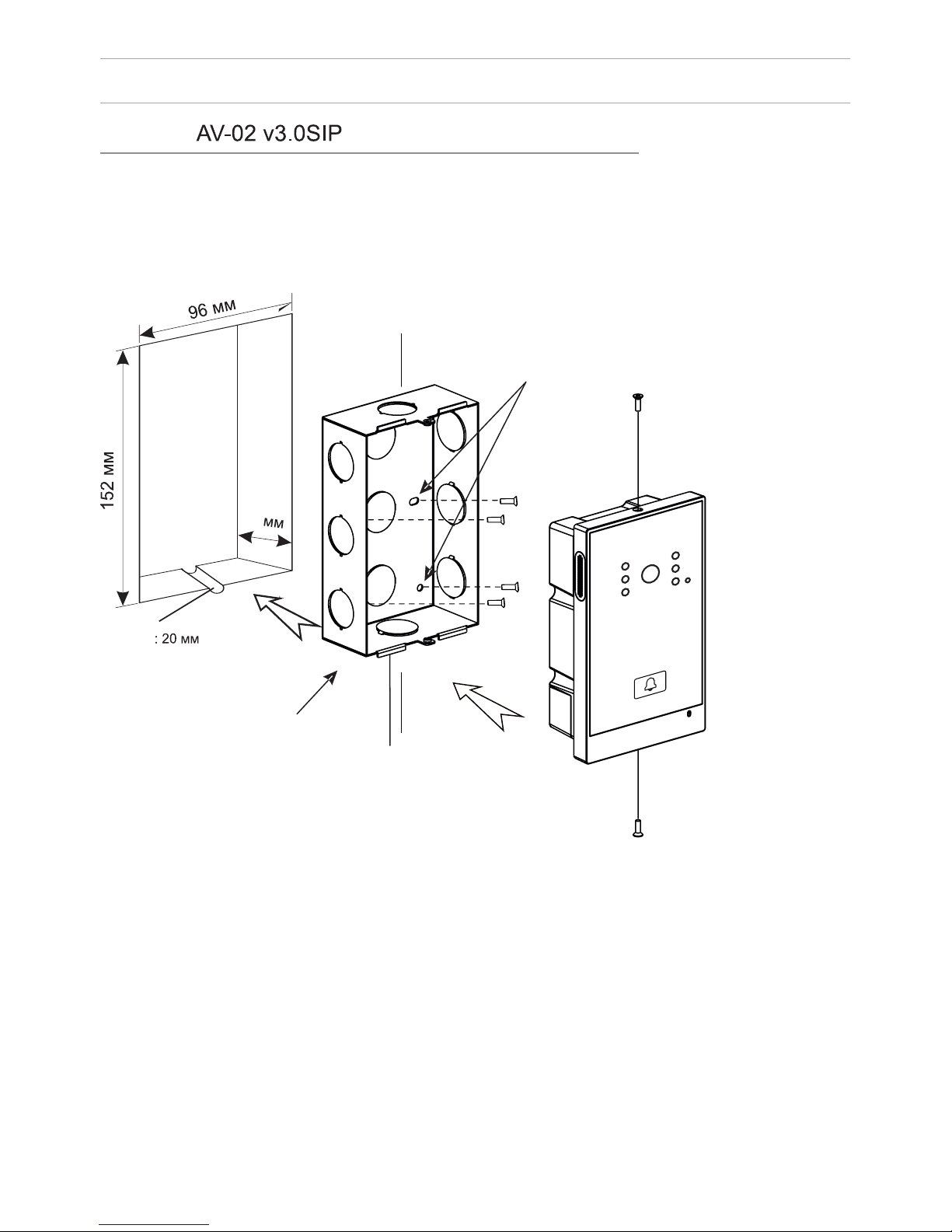
MOUNTING
46
THE HOLES FOR
THE SCREWS
SCREWS
HOLE FOR WATER
RUNOFF. PLEASE DO
NOT COVER DURING
MOUNTING.
BRACKET
GUTTER
15
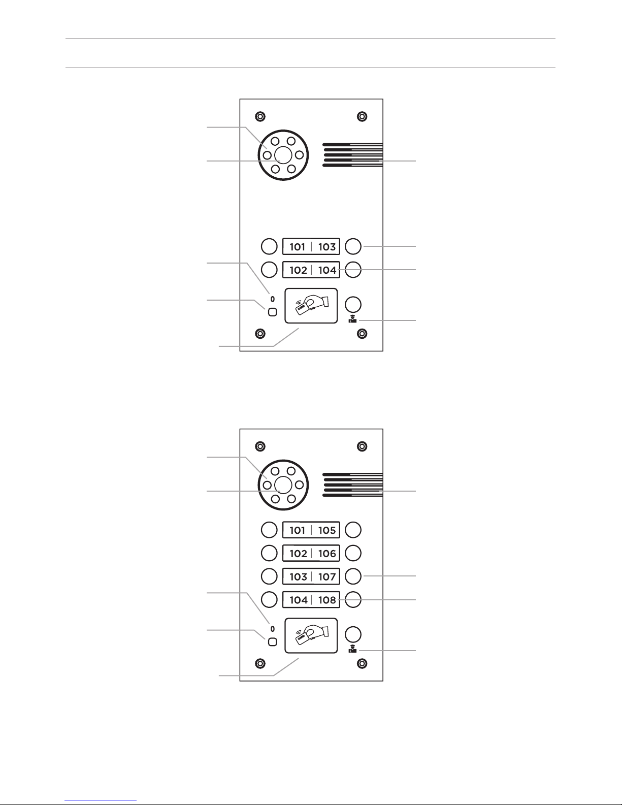
APPEARANCE
Model: BA-04 v3.0SIP
Model: BA-08 v3.0 SIP
Backlight
Backlight
Loudspeaker
Loudspeaker
Call button
Call button
Apartment number
Apartment number
Concierge button
Concierge button
Camera
Camera
Microphone
Microphone
Light sensor
Light sensor
Reader for
contactless
cards and keys
Reader for
contactless
cards and keys
16
SPECIFICATIONS
Panel type
Individual
Screen
No
Camera
1/3”, adjustment of the camera direction
Angle
71° horizontal × 56° vertical
Resolution
800 TVL
Output video
D1 (704×576), H.264 Main Prole,
BaseLine Prole
Night backlight
6 LEDs
Light sensitivity
0,01 Lux
Protection class
IP65
Operating temperature
-40 – +65
0
С
Power consumption
5,5 W, in standby – 2,5 W
Power
+ 12 V
Body
Metal
Colors
Titanium-grey
Dimensions for installation
180×104×60 mm
Dimensions of panel
192×116×45 mm
Installation
Flush mount, wall mount
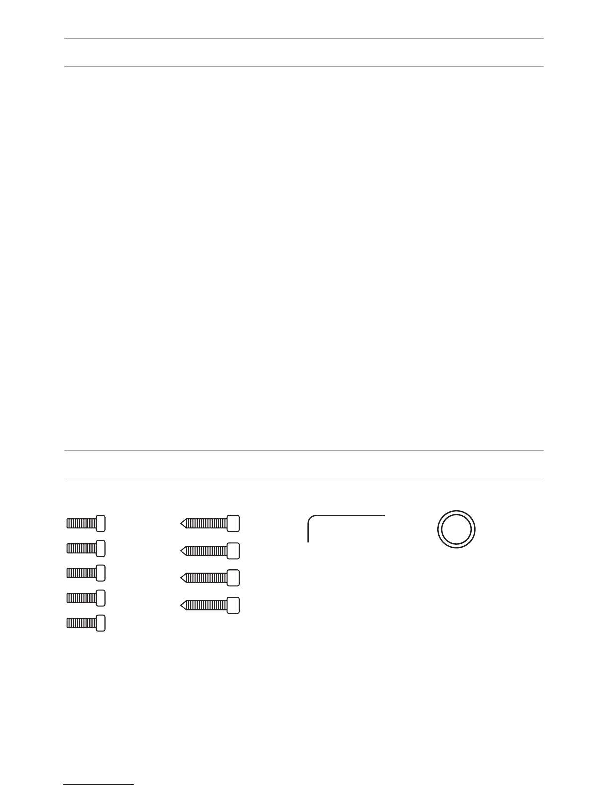
EQUIPMENT
Key
Sealing ring
Set screws
17

SETTING THROUGH WEB INTERFACE
To congure the outdoor panel through the WEB-interface, you must connect to
it with a web browser on a PC. The panel must be connected to the same local
network segment as the PC from which you plan to make the settings. In the
Internet browser in the address bar, enter the IP-address of the outdoor panel,
and then enter the username and password. The username to enter the settings:
admin. The password required for entry must match the password for access to
the outdoor panel settings and is an installer’s password, default: 123456.
1. Network Settings.
Select «Network» to access the network conguration settings.
18
 Loading...