


MATRIX
™
SERIES
MODEL MATRIX 4000 SERIES
SHOWN AS STANDARD WIDTH
WITH OPTIONAL PEDAL LOCK AND
ADVANCED POSITIONING (APS)
FEATURES
INSTRUCTIONS FOR USE
To avoid personal injury or damage to bed,
read all sections pertaining to the bed model before use.
CAN/CSA C22.2 No. 60601-1 (IEC 60601-1:2012-Ed.3.1)
IEC 60601-1, IEC 60601-1-2, IEC 60601-2-52
GF Health Products, Inc. - www.grahamfield.com Matrix Series Instructions for Use 999-0908-190C AUG 2019
FDA Recognized Standard:
ANSI/AAMI STD ES60601-1
Health Canada Recognized Standard:
Includes International Standards:
EMC Standard:
IEC60601-1-2 Ed. 4.0

MATRIX SERIES
TABLE OF CONTENTS
IMPORTANT SAFETY AND WARNING INFORMATION ................................................................................ 3
IMPORTANT SAFETY AND WARNING INFORMATION ..................................................................... 4
ELECTROMAGNETIC COMPATIBILITY (EMC) INFORMATION ........................................................ 4
ENTRAPMENT AND COMPLIANCE INFORMATION .......................................................................... 5
RECOMMENDED MAINTENANCE ................................................................................................................. 6
RECOMMENDED CLEANING AND DISINFECTION ..................................................................................... 7
MECHANICAL AND ELECTRICAL INFORMATION ....................................................................................... 8
OPERATING CONDITIONS .................................................................................................................. 9
STORAGE AND TRANSPORT CONDITIONS ..................................................................................... 9
DISPOSAL OF EQUIPMENT AND ACCESSORIES ............................................................................ 9
BED SETUP AND OPERATION INSTRUCTIONS ........................................................................................ 10
UNPACKING THE BED (MATRIX 4000 SERIES SHOWN) ............................................................... 10
HEADBOARD AND FOOTBOARD ASSEMBLY / INSTALLATION ....................................................11
STANDARD MATTRESS RETAINER INSTALLATION ...................................................................... 15
MATRIX 4000 / 6000 SERIES WIREFORM WALLSAVER INSTALLATION ...................................... 16
MATRIX 4000 / 6000 SERIES — OPERATING THE CASTER PEDAL LOCK MECHANISM ........... 16
MATRIX 5000 SERIES WIREFORM WALLSAVER INSTALLATION ................................................. 17
PLUGGING IN THE FOOTBOARD STAFF CONTROL ..................................................................... 18
MATRIX SERIES OPTIONAL ACCESSORIES .................................................................................. 19
MATRIX SERIES HAND CONTROL PENDANT OPERATION .......................................................... 25
BED OPERATION - OPTIONAL STAFF CONTROL PANEL * ........................................................... 26
BED OPERATION - CHAIR POSITION .............................................................................................. 27
BED OPERATION - TRENDELENBURG / REVERSE TRENDELENBURG POSITION ................... 28
MATRIX 5000 SERIES BED OPERATION — STATIONARY / LOW ROLL POSITIONING .............. 29
TROUBLESHOOTING ................................................................................................................................... 32
NOTHING WORKS — NO POWER .................................................................................................... 32
AUDIBLE SYSTEM WARNING (INTERMITTENT BEEP) .................................................................. 32
KNEE DOESN’T LOWER, AUDIBLE SOLID BEEP WARNING ....................................................... 33
GENERAL TROUBLESHOOTING QUICK REFERENCE ................................................................. 34
LIMITED WARRANTY ................................................................................................................................... 35
These Instructions for Use cover the Matrix Series with Standard and Advanced Positioning (APS),
Standard Casters and Pedal-Lock option, for 35" and 42" Wide beds.
The Matrix Series is designed for Adult Patient and Caregiver use.
To order Matrix Series Bed service parts,
contact a GF Health Products, Inc. customer service representative at 1.770.368.4700.
For a list of Matrix Series bed service parts, visit www.grahameld.com.
To order a Matrix Series bed or accessories,
contact a GF Health Products, Inc. sales representative at 1.770.368.4700.
Important Notice: Check all parts for shipping damage and test before using. In case of damage,
DO NOT USE — contact qualied service personnel for examination and repair.
LABEL SYMBOL DEFINITIONS
!
Consult
Accompanying
Documents
GF Health Products, Inc. - www.grahameld.com Matrix Series Instructions for Use 999.0908-190C
!
Safe
Working
Load
Double
Insulated
Protected
Grounded
Device
Type B
Equipment and
Applied Parts
Follow
Instructions
for Use
2

!
!
!
!
!
!
!
!
!
!
!
!
!
!
!
MATRIX SERIES
IMPORTANT SAFETY AND WARNING INFORMATION
This product is a variable height, adjustable mattress
platform. The expected service life of this product is
fteen years. Beds manufactured by Basic American
Medical Products are designed for use within an
institutional healthcare environment (i.e. assisted
living, skilled nursing, transitional care, rehabilitation
care, Environment (3), as dened in IEC60601-2-52
Safety Standard.).
The maximum safe working load for the Matrix series
bed, including bedding, resident / patient, support
surface, and accessories, is 450 lb (204.1 kg), with
weight evenly distributed, and maximum patient
weight is 400 lb (181.4 kg). Accessory weights follow:
ACCESSORY DESCRIPTION WEIGHT
Extension Kit, Standard Width 12 lb (5.4 kg)
Extension Kit, Wide 14 lb (6.4 kg)
Trapeze Adapter 13 lb (5.9 kg)
Trapeze 16 lb (7.3 kg)
Half Counter-Rotating Assist Device
(Set of 2)
Fixed Assist Bar, Head 6 lb (2.7 kg)
Pivoting Assist Bar 10 lb (4.5 kg)
21 lb (9.5 kg)
The bed’s Hand Control Pendant Cable MUST BE
ROUTED AND SECURED PROPERLY to ensure
it does not become entangled and eventually severed
during use. Also ensure electrical cords DO NOT
get tangled around the bed, side rails, or legs during
transport or normal operation of the bed.
When using nasal-type or masked-type administering
equipment, all oxygen or air tubing MUST BE
ROUTED AND SECURED PROPERLY to ensure
the tubing does not become entangled and eventually
severed during the normal operation of the bed.
Keep all moving parts free of obstructions (i.e.
blankets / sheets, heating blankets / pads, wiring, etc.).
DO NOT use the assist devices as push handles for
moving the bed. Assist devices can be deformed or
broken if excessive side pressure is exerted. Assist
devices are not meant for patients considered high
risks for entrapment (i.e. patients with pre-existing
conditions such as confusion, restlessness, lack of
muscle control, altered mental status, either organic
or medicinal, or a combination thereof). Additional
safety measures should be considered for such highrisk patients.
WARNING: To avoid risk of electric shock, this
equipment must be connected to a supply mains with
protective earth (i.e. a grounded outlet).
DO NOT open assemblies such as the Actuators,
Hand Control Pendant, or Control Box. If
unauthorized personnel perform work on these
components, the manufacturer’s warranty becomes
void.
DO NOT use unauthorized parts, accessories, or
adapters other than those specied / authorized by GF
Health Products, Inc.
When operating the HI/LO, Knee, or Back Functions
of the bed, ALWAYS ensure the conned individual
is positioned properly within the connes of the
bed. DO NOT let any extremities protrude over the
side or between the bed rails when performing these
functions.
The bed should be lowered to lowest position when
resident is left unattended. DO NOT lower the bed
when objects are beneath it. Failure to inspect under
the bed can result in personal injury or property
damage.
NEVER permit more than one person on / in the bed
at any time.
Body weight should be evenly distributed over the
sleeping surface of the bed. DO NOT allow the
patient to lie, sit, or lean in such a way that their
entire body weight is placed only on the raised head
or foot section of the bed. This especially applies
when repositioning or transferring a patient in or
out of the bed. Increased risk may occur when the
patient’s size and / or weight are inappropriate for the
bed’s dimensions or weight capacity.
Risk of entanglement or injury may occur if the
mattress used with mattress retainers does not ll the
entire width between stops or which compresses to
less than 1.50 inches under user’s weight.
Mattress must be properly sized to t the mattress
support platform and must remain centered on
the support platform relative to State and Federal
guidelines. Recommended minimum dimensions of
mattress are 35-36 inches wide and 6 inches deep.
Length and width should match the mattress support
platform. Use of an improperly tted mattress could
result in injury or death. Standard mattresses are 35
inches wide and 6 inches deep, and wide mattresses
are 42 inches wide and 6 inches deep.
GF Health Products, Inc. - www.grahameld.com Matrix Series Instructions for Use 999.0908-190C
3

!
!
!
!
!
!
!
!
!
!
!
!
MATRIX SERIES
IMPORTANT SAFETY AND WARNING INFORMATION
IMPORTANT: Powered air mattress surfaces may
pose a risk of entrapment. Prior to use, ensure the
therapeutic benets outweigh the risk of entrapment.
The bed is intended for use within a temperature
range of 10˚C to 40˚C. It has a water resistance
rating of IPX4 and IS NOT to be power washed or
submerged.
using an appropriate dilution of mild soap and water.
The head / back and knee / foot decks can be lifted
freely by hand for easy cleaning access when patients
are not in the bed. If you lift the head / back or knee
/ foot deck for any reason, take great care when
lowering back down to the prone position - ensure
all body parts are clear of the space between the
deck and the bed prior to slowly lowering any deck
manually. To avoid injury, DO NOT LET DECKS
FALL FREELY FROM ANY ANGLE.
Note: The bed may be cleaned as needed
WARNING: This product can expose you to
chemicals including Di(2-ethylhexyl)phthalate
(DEHP) which is known to the State of California
to cause cancer and birth defects or other
reproductive harm. For more information go to
www.p65warnings.ca.gov/furniture.
WARNING: ALWAYS position bed so that the power
cord and plug are easily accessed.
Proper routing and tie-off of electrical cabling,
especially the power cord, is essential for proper
operation and to ensure safety from electrical shock.
In the event you are replacing any electrical cabling
on your bed, you must ensure the cables are free
from pinch points, obstructions, or stretched so tight
that they may come loose or become damaged. In
addition, cables should be tied off in such a way to
secure them and keep them free from tangling on
any part of the bed during normal operation. Refer to
pages 30 and 31 for proper cable routing.
ELECTROMAGNETIC COMPATIBILITY (EMC) INFORMATION
WARNING: Medical Electrical Equipment needs
special precautions regarding EMC and needs to be
installed and put into service according to the EMC
information provided in this manual.
WARNING: Electronic equipment may be inuenced
by Radio Frequency (RFI). Caution should be
exercised with regard to the use of portable
communications in the area around such equipment.
Portable RF communications equipment (including
peripherals such as antenna cables and external
antennas) should be used no closer than 30 cm (12
inches) to any part of the bed including specied bed
cables. Degradation of the performance of the bed
could result.
IF RFI causes erratic behavior, unplug the
electric bed immediately. Leave unplugged while
transmission is in progress.
WARNING: The use of accessories, transducers,
and cables other than those specied by the
manufacturer may result in increased emissions or
decreased immunity of the bed. GF Health cables
and accessories include motor cables, mains cable,
pendant cables, back up battery and cable, USB port
cable and UBL and cable.
WARNING: This bed should not be used adjacent
to or stacked with other equipment. If adjacent or
stacked use with other equipment is necessary, this
bed and the other equipment should be observed to
verify that they are operating normally.
WARNING: The EMISSIONS characteristics of
this equipment make it suitable for use in industrial
areas and hospitals (CISPR 11 class A). If it is used
in a residential environment (for which CISPR 11
Class B is usually required) this equipment might
not offer adequate protection to radio frequency
communication services. The user might need to
take mitigation measures, such as relocating or reorienting the equipment.
GF Health Products, Inc. - www.grahameld.com Matrix Series Instructions for Use 999.0908-190C
4

MATRIX SERIES
ENTRAPMENT AND COMPLIANCE INFORMATION
On April 10, 2006, the FDA (U.S. Food and Drug
Administration) released long-awaited guidelines for reducing
the risk of bed entrapment: “Hospital Bed System Dimensional
and Assessment Guidance to Reduce Entrapment”. The new
Guidance identies potential entrapment areas and those
body parts most at risk for entrapment; provides design
criteria for manufacturers of new hospital/convalescent beds;
recommends particular test methods to assess the conformance
of existing hospital / convalescent bed systems; and answers
frequently-asked questions about entrapment issues.
The new Guidance was a result of a long-standing
collaboration between the FDA and the Hospital Bed Safety
Workgroup (HBSW), formed in 1999. GF Health Products,
Inc.’s Long Term Care Bed division: Basic American Medical
Products, is an HBSW charter member. As a result of our
commitment to product safety, all our current long-term
care beds have been strictly tested and conform to the new
FDA Guidance.
The guidelines set forth by the FDA Guidance lay out specic
dimensional limitations on potentially injury-threatening gaps
and spaces that can occur between bed system components,
such as rails, when not properly installed. GF Health Products,
Inc. and Basic American Medical Products have conformed
to these guidelines from a manufacturing aspect. However,
entrapment issues can often arise when a healthcare provider /
facility has not correctly assembled the components on a bed.
It is essential that the provider / facility fully understand their
responsibility in complying to the guidelines set forth by the
FDA in order to avoid injury. To that end, we have provided
the FDA’s web address at right as a resource for understanding
and following these guidelines for the safety of patients /
residents.
It is also essential to have the correct bed components /
accessories that correspond with the needs of the patient /
resident and the particular bed you have purchased. Matching
the correct bed component that correlates with the regulatory
guidelines can be a daunting task. Our sales team at GF
Health Products, Inc. and our friendly Customer Service
Representatives at Basic American Medical Products can help
you sift through the wide array of compliance and bed options.
We will help you determine which bed / bed part is best for the
patient’s / resident’s particular needs and help you with any
compliance issues.
The MATRIX series bed and accessories listed in these
instructions are in full compliance with FDA guidelines
for reducing the risk of bed entrapment: “Hospital Bed
System Dimensional and Assessment Guidance to Reduce
Entrapment”.
Details can be found at www.fda.gov.
5
GF Health Products, Inc. - www.grahameld.com Matrix Series Instructions for Use 999.0908-190C

MATRIX SERIES
RECOMMENDED MAINTENANCE
Regular maintenance of the Long Term Bed is necessary to ensure continuing proper and safe operation. Read
and observe the following recommended maintenance schedule.
RECOMMENDED
INSPECTION PERIODS
ITEM
Maintenance Inspection of All Components at Receipt of Shipment
Ensure all parts / components are included (see
“Unpacking The Bed”).
Check all bed components for obvious damage. X
Inspect the power cord for any cuts and / or damage. X
Check to see all actuator / motor cables are routed
and connected properly to the control box.
Mechanical Inspection of Assemblies
Inspect all welds on the sleeping surface, frame, and
base assemblies for stress fractures.
Inspect all fasteners for wear and looseness. X
IMPORTANT: Lubricate all pivot points, actuator /
motor clevis pins, and control arm clevis pins as
needed. White Lithium Grease is recommended.
Mechanical Inspection of Casters and Pedal Locking Mechanism
Check the pedal locking mechanism to ensure it
engages and disengages properly.
Check the casters and stationary foot pads on both
the head end and foot end for any damage, wear, or
debris. Replace if needed.
Check all rolling casters to ensure that they roll
properly and are unobstructed.
Electrical Inspection of Control Box, Hand Control Pendant, and Staff Control
Check the external power cord that plugs into the
control box for any chang, cuts, or wear. Replace if
damaged.
Ensure all attaching hardware is securely tightened. X
Inspect
on Receipt
X
X
Every
3 Months
X
X
X
X
Every
6 Months
MAINTENANCE
Performed byDate Comments
X
X
Check all electrical connections for wear or fractures. X
Check the external backup battery (if you have one).
Replace if needed.
Check the hand control pendant cable for chang,
cuts, or wear.
Check all hand control pendant functions - check to
ensure each button and associated function work
properly (i.e. head section rises when the HEAD UP
button is activated).
Electrical Inspection of Actuators / Motors
Check the actuator / motor cables for any chang,
cuts, or wear.
Check the range of movement on all motors to ensure
they do not bind in the Full Up or Full Down positions.
GF Health Products, Inc. - www.grahameld.com Matrix Series Instructions for Use 999.0908-190C
X
X
X
X
X
6

!
!
!
!
MATRIX SERIES
RECOMMENDED CLEANING AND DISINFECTION
WARNING: Unplug the bed from the electrical outlet before servicing or cleaning.
Do not steam clean or pressure wash any part of bed.
Do not use corrosive or powdered cleansers to clean any part of bed.
Do not immerse or soak any part of bed.
CLEANING
Cleaning/Disinfecting the Metal Components and Mechanical Accessories
All metal parts of the bed have been covered with a baked-on epoxy coating.
• To remove dust from the frame: Carefully raise the head and foot sections of the bed and
wipe the frame with a clean, soft cloth. If disinfection is required, wipe with a clean, soft cloth
dampened with a hospital grade disinfectant diluted per manufacturer’s directions.
• To clean coated metal parts: Wipe with a clean, soft cloth dampened with mild detergent and
warm water. If disinfection is required, wipe with a clean, soft cloth dampened with a hospital
grade disinfectant diluted per manufacturer’s directions.
• To clean the mattress deck: Remove the mattress, then wipe mattress deck with a clean,
soft cloth dampened with mild detergent and warm water. Allow to air dry before replacing
mattress. If disinfection is required, wipe with a clean, soft cloth dampened with a hospital
grade disinfectant diluted per manufacturer’s directions.
Cleaning the Hand Control Pendant and Electrical Components
Wipe the hand control pendant and electrical components’ external surface only with a clean, soft
cloth dampened with mild detergent and warm water. If disinfection is required, wipe with a clean,
soft cloth dampened with a hospital grade disinfectant diluted per manufacturer’s directions.
Air dry.
Cleaning the Mattress
Wipe with a damp cloth to remove any foreign material, then wipe with a clean, soft cloth
dampened with mild detergent and warm water. If disinfection is required, wipe with a clean, soft
cloth dampened with a hospital grade disinfectant diluted per manufacturer’s directions. Air
dr y.
GF Health Products, Inc. - www.grahameld.com Matrix Series Instructions for Use 999.0908-190C
7

!
MATRIX SERIES
MECHANICAL AND ELECTRICAL INFORMATION
MATRIX SERIES-MECHANICAL
Specication 4100 (35") 4100 (42") 5100 (35") 6100 (35")
Overall Bed Length (with boards and wallsaver)
Sleep Deck Width 35" 42" 35" 35"
Bed Width Including Boards 36" 42" 36" 36"
Maximum Height (oor to top of mattress support deck)
Minimum Height (oor to top of mattress support deck) 8.95" 8.95" 8.95" 8.95"
Maximum Head / Back Deck Angle 68° 68° 68° 68°
Maximum Knee / Foot Deck Angle 25° 25° 25° 25°
Maximum Trendelenburg / Reverse Trendelenburg Angle
Maximum Safe Working Load WITH WEIGHT EVENLY
DISTRIBUTED - includes bedding, resident / patient,
support surface, and accessories
Bed Mass (without assist devices or boards) 150 lb
76"
80"
81.2" 81.2" 82.7" 81.2"
83.1" 83.1" 83.9" 83.1"
27" 27" 27" 27"
12° 12° 13° 12°
450 lb
(204.1 kg)
(68.0 kg)
NOTE: All dimensions are ±0.25 inches
450 lb
(204.1 kg)
157 lb
(71.2 kg)
450 lb
(204.1 kg)
157 lb
(71.2 kg)
450 lb
(204.1 kg)
157 lb
(71.2 kg)
MATRIX SERIES-ELECTRICAL (ALL MODELS)
Power / Frequency 120 Volt / 50/60 Hz
Output Rating 24Vdc
Maximum Amperage 4.0 Amps
Classication Class 1, Type B
Power (Electrical) Cord #18 AWG 3 Conductor Type SJT
Mode of Operations 10% Max. Duty Cycle (2 minutes on / 18 minutes off)
Battery Pack and Charger can be purchased separately as accessories.
TYPICAL MATRIX SERIES BED IDENTIFICATION LABELS
with Grounded Electrical Cable
Bed labels are an important part of identifying the bed’s
make and model when ordering replacement parts. The
Serial Number is essential if you are claiming parts or
service under warranty. These helpful labels can be
located on the main frame rails, immediately below the
sleep decks on either side of the bed.
Have this IMPORTANT information ready when calling
our Customer Service or Technical Support staff at
1.770.368.4700; it will allow us to better assist you and
quickly answer your questions and concerns.
WARNING:
authorization from GF Health Products, Inc.
NOTE: For Matrix Series Service Parts, Technical
Assistance, and Information, call our Customer
Service Department at 1.770.368.4700.
list of Matrix Series bed service parts, visit
www.grahameld.com.
GF Health Products, Inc. - www.grahameld.com Matrix Series Instructions for Use 999.0908-190C
Do not modify this equipment without
For a
8

MATRIX SERIES
The following warning labels have been placed on the bed to help protect you and the bed from
damage. Do not remove any labels from the bed.
WARNING!
DO NOT LOWER BED WHEN OBJECTS ARE
BENEATH BED. FAILURE TO INSPECT UNDER
BED CAN RESULT IN DAMAGE TO PROPERTY
OR PERSONAL INJURY.
ATTENTION:
S’assurer de ne pas faire descendre le lit
lorsque des objets se trouvent sous le lit. Ne
pas inspecter le dessous du lit pourrait entrainer
des dommages materiels et des risques de
blessures.
THIS BED IS SUITABLE FOR USE ONLY WITH
OXYGEN ADMINISTERING EQUIPMENT OF
THE NASAL OR MASK TYPE OR A TENT
COVERING ONLY THE UPPER HALF (HEAD
END) OF THE BED. OXYGEN TENT CANOPIES
SHOULD NOT EXTEND BELOW BED SPRING
LEVEL. LOCK HAND CONTROL AT FOOT OF
BED WHEN USING OXYGEN ADMINISTERING
EQUIPMENT.
WARNING!
DO NOT LOWER BED WHEN
OBJECTS ARE BENEATH BED.
FAILURE TO INSPECT UNDER
BED CAN RESULT IN DAMAGE
TO PROPERTY OR PERSONAL
INJURY.
ENVIRONMENTAL SPECIFICATIONS
OPERATING CONDITIONS
Ambient Temperature 10°C to 40°C
Relative Humidity
Atmospheric Pressure 700 hPa to 1060 hPa
Protected Against
Splashing Water
30% to 75% Non-Condensing
IPX4
CAUTION
ATTENTION:
CE LIT PEUT ETRE UTILISE UNIQUEMENT
AVEC UN EQUIPMENT DESTINE A
L’ADMINISTRATION D’OXYGENE DE TYPE
NASAL OU MASQUE OU AVEC UNE TENTE
RECOUVRANT SEULEMENT LA MOTTIE
AVENT (TETE) DU LIT. LES COTES DE LAS
TENTE OXYGENE NE DOIVENT PAS SE
PROLONGER PLUS DAS QUE LA SOMMIER
DU LIT.
STORAGE AND TRANSPORT CONDITIONS
Temperature -10°C to 50°C
Relative Humidity 20% to 90%
Atmospheric Pressure 700 hPa to 1060 hPa
.
WARNING:
Incompatible mattresses can create hazards.
Read Instructions for use.
ATTENTION:
Matelas incompatibles peuvent créer des
dangers.
Lisez les Instructions d’utilisation.
DISPOSAL OF EQUIPMENT AND ACCESSORIES
Follow local governing ordinances and recycling plans regarding disposal of the device or
components normally used in operation. The device does not generate waste or residue in
operation. Any accessories not part of the device MUST be handled in accordance with the
individual product marking for disposal.
9
GF Health Products, Inc. - www.grahameld.com Matrix Series Instructions for Use 999.0908-190C

MATRIX SERIES
BED SETUP AND OPERATION INSTRUCTIONS
UNPACKING THE BED (MATRIX 4000 SERIES SHOWN)
• Ensure all parts / components are included.
•
Check all bed components for obvious damage.
• Inspect the Power Cord for cuts or damage.
• Ensure all actuator / motor cables are routed
and connected properly to the control box.
DISCARD
1) Foam Block (4)
2) Honeycomb Block (8)
3) Shipping Board (1)
4) Cable Tie (3) - Cut and Discard
KEEP
5) Panel Mount Kit
6) Mattress Retainer
7) Pendant Holster
8) Wireform Wallsaver
NOTE:
END OF POWER
CORD IS COILED
FOR SHIPPING
AND TIED, WITH
CABLE TIE, TO GRID
WIRE WITH HAND
CONTROL PENDANT,
PENDANT CABLE AND
HOLSTER.
10
GF Health Products, Inc. - www.grahameld.com Matrix Series Instructions for Use 999.0908-190C

MATRIX SERIES
HEADBOARD AND FOOTBOARD ASSEMBLY / INSTALLATION
MATRIX 4000 SERIES
MATRIX 4000 SERIES HEADBOARD
INSTALLATION *
1.
The headboard may come with four
pre-installed
assemble the four inserts into the outside of
the headboard as shown above.
2. Position a right (#1) and left (#2) mounting
bracket on the inside of the headboard with
headboard mounting holes facing outward
as shown above.
3. Align the bracket top holes with the
headboard top holes.
4. Insert a screw (#4) through each of the top
holes and bottom holes and screw into each
insert. Tighten loosely (hand tight) until after
brackets are fastened to the bed frame.
GF Health Products, Inc. - www.grahameld.com Matrix Series Instructions for Use 999.0908-190C
inserts - if not already installed,
5. At the head deck end, slide the brackets into
the main frame rail hollow ends.
6. FOR 80" BEDS: Slide the brackets in until
the bracket hole aligns with the lower rail hole
as shown above. 76" and 80" bracket labels
will be visible. Pin brackets to frame with
Clevis Pins and Hair Pins provided.
7. FOR 76" BEDS: Slide the mounting brackets
in until the bracket hole aligns with the upper
rail hole as shown above. Only 76" bracket
label will be visible. Pin brackets to frame
with Clevis Pins and Hair Pins provided.
8. Tighten screws with the hex key included in
the kit.
11

MATRIX 4000 SERIES FOOTBOARD
INSTALLATION
MATRIX SERIES
1.
The footboard may come with four
pre-installed
assemble the four inserts into the outside of
the footboard as shown above.
2. Position a right (#1) and left (#2) mounting
bracket on the inside of the footboard with
footboard mounting holes facing outward as
shown above.
3. Align the bracket top holes with the
footboard top holes.
4. Insert a screw (#4) through each of the top
holes and bottom holes and screw into each
insert. Tighten loosely (hand tight) until after
brackets are fastened to the bed frame.
* For residents taller than 185 cm (6' 1"),
a 4" Length Extension Kit is available.
Please contact Customer Service for more
information.
inserts - if not already installed,
5. At the foot deck end, slide the brackets into
the main frame rail hollow ends.
6. FOR 80" BEDS: Slide the mounting brackets
in until the bracket hole aligns with the
rst rail hole as shown above. 76" and 80"
bracket labels will be visible. Pin brackets
to frame with Clevis Pins and Hair Pins
provided.
7. FOR 76" BEDS: Slide the mounting brackets
in until the bracket hole aligns with the
second rail hole as shown above. Only 76"
bracket label will be visible. Pin brackets
to frame with Clevis Pins and Hair Pins
provided.
8. Tighten screws with the hex key included in
the kit.
12
GF Health Products, Inc. - www.grahameld.com Matrix Series Instructions for Use 999.0908-190C

MATRIX 5000 / 6000 SERIES
MATRIX 5000 / 6000 SERIES HEADBOARD
INSTALLATION *
MATRIX SERIES
1.
The headboard may come with four
pre-installed
assemble the four inserts into the outside of
the headboard as shown above.
2. Position a right (#1) and left (#2) mounting
bracket on the inside of the headboard with
headboard mounting holes facing outward
as shown above.
3. Align the bracket top holes with the
headboard top holes.
4. Insert a screw (#4) through each of the top
holes and bottom holes and screw into each
insert. Tighten loosely (hand tight) until after
brackets are fastened to the bed frame.
inserts - if not already installed,
5. At the head deck end, slide the brackets into
the main frame rail hollow ends.
6. FOR 80" BEDS: Slide the brackets in until
the rst bracket hole aligns with the upper rail
hole as shown above. 76" and 80" bracket
labels will be visible. Pin brackets to frame
with Clevis Pins and Hair Pins provided.
7. FOR 76" BEDS: Slide the mounting brackets
in until the second bracket hole aligns with
the upper rail hole as shown above. Only
76" bracket label will be visible. Pin brackets
to frame with Clevis Pins and Hair Pins
provided.
8. Tighten screws with the hex key included in
the kit.
13
GF Health Products, Inc. - www.grahameld.com Matrix Series Instructions for Use 999.0908-190C

MATRIX 5000 / 6000 SERIES FOOTBOARD
INSTALLATION
MATRIX SERIES
1.
The footboard may come with four
pre-installed
assemble the four inserts into the outside of
the footboard as shown above.
2. Position a right (#1) and left (#2) mounting
bracket on the inside of the footboard with
footboard mounting holes facing outward as
shown above.
3. Align the bracket top holes with the
footboard top holes.
4. Insert a screw (#4) through each of the top
holes and bottom holes and screw into each
insert. Tighten loosely (hand tight) until after
brackets are fastened to the bed frame.
* For residents taller than 185 cm (6' 1"),
a 4" Length Extension Kit is available.
Please contact Customer Service for more
information.
inserts - if not already installed,
5. At the foot deck end, slide the brackets into
the main frame rail hollow ends.
6. FOR 80" BEDS: Slide the mounting
brackets in until the bracket hole aligns
with the rst rail hole as shown above. 76"
and 80" bracket labels will be visible. Pin
brackets to frame with Clevis Pins and Hair
Pins provided.
7. FOR 76" BEDS: Slide the mounting
brackets in until the bracket hole aligns
with the second rail hole as shown above.
Only 76" bracket label will be visible. Pin
brackets to frame with Clevis Pins and Hair
Pins provided.
8. Tighten screws with the hex key included in
the kit.
14
GF Health Products, Inc. - www.grahameld.com Matrix Series Instructions for Use 999.0908-190C

MATTRESS RETAINER
!
!
MATRIX SERIES
STANDARD MATTRESS RETAINER INSTALLATION
USING 35" OR 42" WIDTH MATTRESS RETAINER
Matrix 5000 / 6000
Mattress Retainer
DETAIL A:
INSERT HEAD END
Matrix 4000
Mattress Retainer
Inside holes
for 76" Beds
MATTRESS RETAINER
Outside holes
for 80" Beds
The Matrix Series Bed mattress retainer was designed to span the width of the sleeping surface.
One retainer is shipped with the Matrix 4000 and will t on the Foot End as shown (Note: An optional retainer can be
ordered separately for the head end of the Matrix 4000 Series beds).
Two retainers, one for each end, are shipped with the Matrix 5000 / 6000.
1. Determine if you need to position your bed in an 80" or 76" conguration (80" length bed = outside holes; 76" length
bed = inside holes).
2. Carefully squeeze the Mattress Retainer ends inward, toward the center of the retainer, and insert the ends into the
proper holes. Lay the Mattress Retainer down so that the elbows rest on the decks and the long cross rod faces away
from the bed as shown.
IMPORTANT: Ensure all three adjustable parts are properly positioned for 76" or 80" congurations
(see pages 11, 12, 13, 14 and 16).
DETAIL B:
INSERT FOOT END
Be sure to use a mattress that is properly sized to t
the sleep deck, which will remain centered on the
deck relative to State and Federal Guidelines. Use of
an improperly tted mattress could result in injury or
death.
GF Health Products, Inc. - www.grahameld.com Matrix Series Instructions for Use 999.0908-190C
Use a properly sized mattress in order to minimize
the gap between the side of the mattress and assist
devices. This gap must be small enough to prevent
resident / patient from getting their head or neck
caught in this location.
15

Pedal Lock Engaged (RED DOWN = LOCKED POSITION)
MATRIX SERIES
MATRIX 4000 / 6000 SERIES WIREFORM WALLSAVER INSTALLATION
WALLSAVER ASSEMBLY
1. Position the Wireform Wallsaver
with bent end facing upward and
tab ends facing inward as shown at
right.
2. Determine the position desired (see
WALLSAVER POSITIONS below).
3. Gently squeeze the wallsaver tab
ends inward toward the center of
the wallsaver and, holding the tabs
parallel with the caster base holes,
slide the tabs into the holes while
letting the wallsaver gently expand
outward.
4. Turn the wallsaver downward until it
rests on the oor.
WALLSAVER REMOVAL
1. To remove or move the wallsaver to
a new position, raise the wallsaver
off the oor until the end tabs are
horizontal.
2. Squeeze the ends toward the center
of the wallsaver until the end tabs
slide out of the caster base holes.
WALLSAVER POSITIONS
There are two positions for the Matrix series wallsaver. Holes nearest the center of the bed are for both 76" and 80" beds,
and the holes closest to the head end are for use when a Trapeze Adapter is added to the bed.
The Standard Wallsaver will prevent the bed from making contact with the wall in all positions except Trendelenburg. If the
Advanced Positioning (APS) bed is to be used in Trendelenburg position, the Trendelenburg Wallsaver must be used to
prevent the bed from making contact with the wall.
A Trendelenburg Wallsaver is available when the bed is ordered with a Staff Control with Advanced Positioning.
MATRIX 4000 / 6000 SERIES —
OPERATING THE CASTER PEDAL
LOCK MECHANISM
LOCKED POSITION
To lock the foot end casters, step on the red pedal until the
caster lock engages.
UNLOCKED POSITION
To unlock the foot end casters, step on the green release pedal
until the caster lock disengages.
GREEN DOWN = ROLL
FOOT END
RED DOWN = LOCKED
FOOT END of Matrix 4000 Series Bed Shown with
GF Health Products, Inc. - www.grahameld.com Matrix Series Instructions for Use 999.0908-190C
16

MATRIX SERIES
MATRIX 5000 SERIES WIREFORM WALLSAVER INSTALLATION
WALLSAVER ASSEMBLY
1. Position the Wireform Wallsaver with bent end facing upward and tab ends facing inward as shown above.
2. Determine the position desired (see WALLSAVER POSITIONS below).
3. Gently squeeze the wallsaver tab ends inward toward the center of the wallsaver and, holding the tabs parallel with the
caster base holes, slide the tabs into the slots while letting the wallsaver gently expand outward.
4. Turn the wallsaver downward until it rests on the oor.
WALLSAVER REMOVAL
1. To remove or move the wallsaver to a new position, raise the wallsaver off the oor until the end tabs are horizontal.
2. Squeeze the ends toward the center of the wallsaver until the end tabs slide out of the caster base slots.
WALLSAVER POSITIONS
1. The Matrix 5000 Series wallsaver features two standard positions for easy bed / mattress length recongurations - 76"
and 80".
2. For 76" beds, position the wallsaver ends in the BACK caster base slots (toward the foot end). For 76" beds using an
optional Trapeze unit, position the wallsaver ends in the FRONT caster base slots (toward the head end.)
3. For 80" beds, position the wallsaver ends in the FRONT caster base slots (toward the head end).
4. If you plan to use an optional Trapeze unit for an 80" length bed conguration, you will need to order a separate
“custom wallsaver” in order to have the correct depth to protect your walls.
17
GF Health Products, Inc. - www.grahameld.com Matrix Series Instructions for Use 999.0908-190C

MATRIX SERIES
PLUGGING IN THE FOOTBOARD STAFF CONTROL
STEP 1 - ATTACHING THE FOOTBOARD
The Matrix series bed features a footboard Staff Control; however, the footboard is ordered separately
with your bed because of the variety of board styles available. If ordered at the same time as the bed, the
Staff Control Assembly and Shroud Cover will be pre-installed to the Footboard at the factory.
STEP 2 - CONNECTING THE CABLES: REFER
TO DETAIL A AT RIGHT
a) Insert the T-Cable end (extending out the foot
end with phone jack) into the round plug, making
sure the phone jack is seated correctly inside the
female plug (arrow to arrow – see DETAIL A at
right and photos below).
Align
Arrows
DETAIL A:
Ensure lock end caps
are screwed on securely
Improper Connection
(not completely seated)
Proper Connection
(completely seated)
b) Screw on the round lock cap onto the Staff Control female plug to secure as shown above.
18
GF Health Products, Inc. - www.grahameld.com Matrix Series Instructions for Use 999.0908-190C

MATRIX SERIES
MATRIX SERIES OPTIONAL ACCESSORIES
MATRIX 4100 SERIES ONLY OPTIONAL ACCESSORIES
Pivot Assist Bar Fixed Assist Bar
ZA90350 ZA80300
Counter-Rotating Assist (set of 2) Head End Mattress Retainer
ZA78400 35" Deck: 999-0822-001SP
42" Deck: 999-0902-001SP
4-Inch Length Extension Kit
35" Deck: ZA90000
42" Deck: ZA90200
19
GF Health Products, Inc. - www.grahameld.com Matrix Series Instructions for Use 999.0908-190C

MATRIX SERIES
MATRIX 5100 / 6100 SERIES ONLY OPTIONAL ACCESSORIES
Pivot Assist Bar Fixed Assist Bar
ZA90300 ZA85000
Counter-Rotating Assist (pair) 42" Width Extension Kit
4-Inch Length Extension Kit (extends 35" & 42")
ZA91300
ZA90840 ZA851000
20
GF Health Products, Inc. - www.grahameld.com Matrix Series Instructions for Use 999.0908-190C

MATRIX SERIES
MATRIX 4100 / 5100 / 6100 SERIES OPTIONAL ACCESSORIES
Trapeze Adapter Kit Trapeze
ZA90100 ZA78100
Long (Trendelenburg) WallSaver Side-WallSaver Bumper (set of 2)
ZA90070 ZA86200 (35")
ZA89200 (42")
21
GF Health Products, Inc. - www.grahameld.com Matrix Series Instructions for Use 999.0908-190C

MATRIX SERIES
Board-Mounted Hand Control Pendant Holster Backup Battery & Battery Charger
Call Customer Service at 1.770.368.4700 Backup Battery: 999-0831-003
Battery Charger: 999-0711-002
USB Phone Charger-Power Supply Kit Under-Bed-Light Kit (must be used with Staff Control
and/or APS Hand Control Pendant)
ZA90020 ZA90010
Advanced Positioning Hand Control with
Trendelenburg / Reverse Trendelenburg
ZA900306 999-0914-305SP
Advanced Positioning Hand Control
with Chair Position only
22
GF Health Products, Inc. - www.grahameld.com Matrix Series Instructions for Use 999.0908-190C

Advanced Positioning Staff Control
ZL90000
Standard Positioning Staff Control
MATRIX SERIES
ZL90050
Board-Mounted IV Socket Kit Edema Foot Ratchet Kit
ZA19000 ZA90030
23
GF Health Products, Inc. - www.grahameld.com Matrix Series Instructions for Use 999.0908-190C

MATRIX SERIES
1-Person Bed Transport Dolly (set)
ZA89900 unassembled ZA89900 assembled with bed
24
GF Health Products, Inc. - www.grahameld.com Matrix Series Instructions for Use 999.0908-190C

MATRIX SERIES
MATRIX SERIES HAND CONTROL PENDANT OPERATION
1
2
3
MATRIX SERIES WITH
STANDARD POSITIONING
HAND CONTROL PENDANT
5
1
6
2
4
3
7
1111
MATRIX SERIES WITH
ADVANCED POSITIONING
HAND CONTROL PENDANT
BUTTON FUNCTION
1 HEAD DECK ANGLE UP
2 HEAD DECK ANGLE DOWN
3 HI/LO UP (RAISE ENTIRE BED)
4 HI/LO DOWN (LOWER ENTIRE BED)
5 KNEE AND FOOT DECK ANGLE UP
6 KNEE AND FOOT DECK ANGLE DOWN
1
5
5
6
7
4
3
8
9
12
11
OPTIONAL ACCESSORY:
MATRIX SERIES WITH
TRENDELENBURG /
REVERSE TRENDELENBURG
HAND CONTROL PENDANT
2
6
8
4
10
BUTTON FUNCTION
7 SET TO CHAIR POSITION
8 UNDO CHAIR POSITION
9 REVERSE TRENDELENBURG POSITION
10 TRENDELENBURG POSITION
11 OPTIONAL UNDERBED LIGHT
12 OPTIONAL HI/LO FUNCTION LOCKOUT
NOTE: The MATRIX Series Hand Control Pendant can be plugged into the T-Cable plugs on either
side of the bed for easy access. The opposite side of the T-Cable should always have the provided
cap attached for safety.
The two vertical ends of the double T-Cable run toward the foot end of the bed, with one vertical end
plugging directly into the control box (or optional Underbed Light if your bed has that feature) and the
other longer end runs along the tie rod and extends out the foot end and plugs into the Staff Control cable.
Optional HI/LO Function Lockout (Hand Control Pendant with Advanced Positioning ONLY,
shown at above center)
A Lockout Key, shown at right, is used to activate/
deactivate the HI/LO Function Lockout by holding it over
the center bottom portion of the hand control as shown
at center right. The Lockout LED indicator will turn on/off
when activated/deactivated.
GF Health Products, Inc. - www.grahameld.com Matrix Series Instructions for Use 999.0908-190C
Lockout
Key
25

MATRIX SERIES
BED OPERATION - OPTIONAL STAFF CONTROL PANEL *
* Staff Control with Advanced Positioning
functions is shown above. Staff Control with
Standard Positioning functions is shown at
left; all standard functions operate the same as
those dened above.
26
GF Health Products, Inc. - www.grahameld.com Matrix Series Instructions for Use 999.0908-190C

MATRIX SERIES
BED OPERATION - CHAIR POSITION
3 2
HEAD
END
1
1. Ensure the Chair position on the Staff
Control panel is not locked out (orange lock
icon). To unlock, press Lock icon button #1
and Chair icon button #2 (or “All Locked”
button #3) simultaneously.
4
2. To move the bed to Chair position (foot and
knee decks angled up, head deck angled
up, and head of bed tilted up), press Chair
icon button #2.
To release the chair feature and return the bed
to horizontal position, press Flat Bar icon #4.
FOOT
END
The Chair feature can also be operated using the Hand Control Pendant.
Chair position
UP and DOWN
buttons
MATRIX SERIES WITH
ADVANCED POSITIONING
HAND CONTROL PENDANT
GF Health Products, Inc. - www.grahameld.com Matrix Series Instructions for Use 999.0908-190C
MATRIX SERIES WITH TRENDELENBURG /
OPTIONAL ACCESSORY:
REVERSE TRENDELENBURG
HAND CONTROL PENDANT
27

BED OPERATION - TRENDELENBURG /
REVERSE TRENDELENBURG POSITION
1. Ensure the Staff Control HI/LO
function is not locked out
(orange lock icon). To unlock,
simultaneously press Key 1
and HI/LO Locked button 2.
2. To move the bed to Trendelenburg
position (foot end up), press
button 3.
3. To move the bed to Reverse
Trendelenburg position (head
end up), press button 4.
MATRIX SERIES
Matrix 4000 Shown
28
GF Health Products, Inc. - www.grahameld.com Matrix Series Instructions for Use 999.0908-190C

MATRIX SERIES
MATRIX 5000 SERIES BED OPERATION —
STATIONARY / LOW ROLL POSITIONING
The Matrix 5000 Series is sold as a “Low Roll” bed, giving the user the option of placing it in a stationary
(non-moving) position or lowering it into a “low roll” position. This is accomplished by lowering the bed
until the stationary foot pads rise off the oor and the rolling casters contact the oor surface for easy
mobility.
29
GF Health Products, Inc. - www.grahameld.com Matrix Series Instructions for Use 999.0908-190C
Optional Battery
Cable Connector
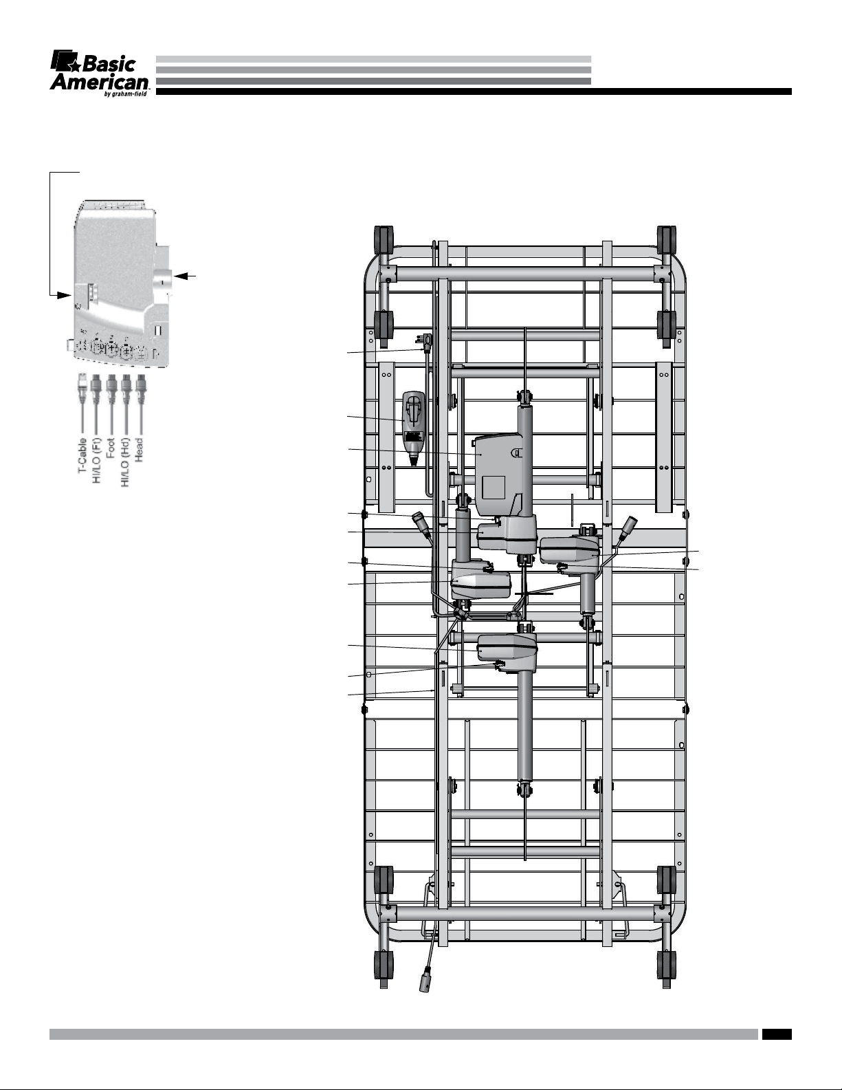
CONTROL
MATRIX SERIES
MATRIX 4000 SERIES ELECTRICAL CABLING
HEAD END
BOX
Power Cord
Connector
Power Cord
Hand Control Pendant
Control Box
Actuator Cable
HI/LO Actuator
(Head End)
Actuator Cable
Head Actuator
HI/LO Actuator
(Foot End)
Actuator Cable
Control Cable
Foot Actuator
Actuator Cable
31
FOOT END
30
GF Health Products, Inc. - www.grahameld.com Matrix Series Instructions for Use 999.0908-190C
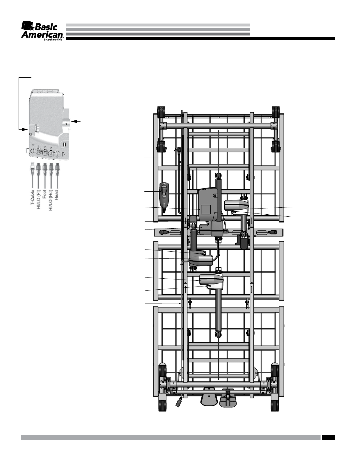
MATRIX 5000 / 6000 SERIES ELECTRICAL CABLING
FOOT END
Optional Battery
Cable Connector
CONTROL
MATRIX SERIES
HEAD END
BOX
Power Cord
Connector
Power Cord
Hand Control Pendant
Control Box
Actuator Cable
HI/LO Actuator
(Head End)
Actuator Cable
Head Actuator
HI/LO Actuator
(Foot End)
Actuator Cable
Control Cable
Foot Actuator
Actuator Cable
31
GF Health Products, Inc. - www.grahameld.com Matrix Series Instructions for Use 999.0908-190C

MATRIX SERIES
TROUBLESHOOTING
NOTHING WORKS — NO POWER
1. Verify the outlet is supplying power.
2. Ensure the power cord is not pinched,
frayed, or damaged in any way. Replace the
Power Cord if damaged.
3. Ensure all power cord, T-Cable, Hand
Control Pendant, and Control Box
receptacles and plugs are seated and fully
inserted.
4. Ensure the Staff Control does not have
functions locked out.
5. Plug the Hand Control Pendant directly into
the Control Box. If the bed works, replace
the T-Cable.
AUDIBLE SYSTEM WARNING (INTERMITTENT BEEP)
NOTE: A function that is faulty or has lost
motor position will cause the Control Box
to beep intermittently when the faulty
function’s Hand Control Pendant button is
depressed. All buttons depressed after the
error function will also be non-functional
and will cause a Control Box beep. If
equipped with a Staff Control, the staff icons
will also ash to indicate a system error.
When the Audible Beeping Error signal is
heard:
1.
On the Hand Control Pendant, simultaneously
press and hold both the HI/LO UP and
HI/LO DOWN buttons (the Control Box
should start beeping) for approximately ve
seconds until beeping stops.
2. Reinitialize the motors by lowering the bed
completely. In the following order, press
the Hand Control Pendant buttons until the
motors stop:
a. HI/LO DOWN
b. HEAD DECK ANGLE DOWN
c.
KNEE AND FOOT DECK ANGLE DOWN
6. Replace the Hand Control Pendant with a
known good operating Pendant. If the bed
works, replace the Hand Control Pendant.
7. If the bed still isn’t functional after steps 1-6,
replace the Control Box.
8. New Control Box installation will require
motor Initialization.
NOTE: Service Control Box Motor
Initialization Procedure as well as detailed
troubleshooting and service instruction can
be found at www.grahameld.com.
3. This lowering of the motors will reset
the system and should resolve minor
synchronization or position lost issues.
Check the bed functionality.
4. If an audible error beep occurs during reset
lowering of a function or while checking
functionality, the function that initiated the
beep is faulty.
5. After the faulty function initiates the beep,
all other button functions will cause a beep
and become non-functional.
6. To operate and use the other good
functions, perform step 1 again to reset the
system.
7. Reinitialize the motors as in Step 2 but only
lower the motors that did not initiate the
audible error beep.
8. These functions will operate normally until
the faulty function button is pressed again.
NOTE: If the issue is not resolved, go to
www.grahameld.com for more detailed
troubleshooting and service instructions.
32
GF Health Products, Inc. - www.grahameld.com Matrix Series Instructions for Use 999.0908-190C

MATRIX SERIES
KNEE DOESN’T LOWER, AUDIBLE SOLID BEEP WARNING
NOTE: As a result of the bed’s programmed
capability to achieve APS positioning,
the Knee Motor will not lower if the
HI/LO motors are not level. This is a safety
measure to prevent the patient from sliding
out of bed while in Chair Position.
The control box will emit a solid beep
warning when attempting to lower the knee
if this condition is present.
NOTE: This condition can also happen with
beds not equipped with APS positioning or
if the frame appears to be visually level.
If the solid beep is present when trying to
lower the knee:
1. Return the bed frame to a level position
by pressing the Hand Control Pendant
UNDO CHAIR button until the bed is level.
Continue holding the button down until the
knee retracts.
2. If not equipped with chair function, or if
step 1 did not resolve the issue, lower the
bed completely: press the HI/LO DOWN
button until the motors shut off.
3. Now lower the knee using the
KNEE AND FOOT DECK ANGLE DOWN
button.
NOTE: If the issue is not resolved, go to
www.grahameld.com for more detailed
troubleshooting and service instructions.
33
GF Health Products, Inc. - www.grahameld.com Matrix Series Instructions for Use 999.0908-190C

MATRIX SERIES
GENERAL TROUBLESHOOTING QUICK REFERENCE
NOTE: Advanced Service Troubleshooting Procedures, Flow Charts and Service Components
can be found at www.grahameld.com.
Optional Battery
Cable Connector
CONTROL
BOX
Power Cord
Connector
Plugs and Receptacles:
Loose plug connections or incorrect plug
positioning will result in erroneous or no
system error signals and faulty operation.
Before troubleshooting, ensure all plugs
are engaged fully in their receptacles and
located in the correct ports.
head motor into the knee Control Box port and
operate the head motor with the knee Pendant
button. If the head motor operates, it is good. If
not working in the good port, replace the head
motor or motor cable.
Motor Cables
Motor cables are interchangeable. Test a
motor cable by attaching it to a known good
motor and known good Control Box port and
operating it.
T-Cables
Test a T-Cable by unplugging it from the
Control Box port and plugging the Hand
Control Pendant directly into the Control Box.
If the bed functions with the Hand Control
Pendant, replace the T-Cable.
Hand Control Pendants
Test a Hand Control Pendant by replacing it
with a known good Pendant. If the Bed now
operates, replace the Hand Control Pendant.
Staff Controls
Test a Staff Control by replacing it with a known
good Staff Control. If the Bed now operates,
replace the Staff Control.
Control Box
Test a Control Box by replacing it with a
known good Control Box. If the bed now
operates, replace the Control Box. If a
known good Control Box is not available,
Motors
go to www.grahameld.com for detailed
Troubleshooting Procedures.
Test any motor by plugging it into a known
good Control Box port.
Example: If the head motor is not functioning
and the knee motor is functional, plug the
34
GF Health Products, Inc. - www.grahameld.com Matrix Series Instructions for Use 999.0908-190C

MATRIX SERIES
LIMITED WARRANTY
SCOPE OF WARRANTY
GF Health Products, Inc. (“GF”) warrants to the original purchaser only that it will replace or repair components, at GF’s sole discretion,
that are defective in material or workmanship under normal use and service. All warranties are conditioned upon the proper use of the
products strictly in accordance with good commercial practice and applicable GF instructions and manuals, including proper use and
maintenance. To the extent that a component is warranted by a third party, GF conveys all of its rights under that warranty to the original
purchaser, to the extent permitted.
This limited warranty shall only apply to defects that are reported to GF’s customer service team within the applicable warranty
period and which, upon examination by GF or its authorized representative, prove to be a warranty item. This limited warranty is not
transferable.
The warranted components and time period are set forth below:
Main Frame and welds: ................................................... fteen years
Control Box and Actuator Motors: ...................................four years
Hand Control Pendant, Staff Control, and Cabling ......... three years
Headboard and Footboard .............................................. one year
All other durable components not listed above: .............. two years
Subsequent service parts under warranty until the original warranty set forth above expires, or for one year, whichever is greater.
The applicable warranty period shall commence from date of shipment to the original customer, unless there is an expiration date on
the component in which case the warranty shall expire on the earlier of warranty period or the expiration date.
OBTAINING WARRANTY SERVICE
A GF Customer Service Representative must authorize warranty service. Please contact the GF Customer Service department by
calling 1.770.368.4700, sending a fax request to or by e-mailing a request to cs@grahameld.com. Specic directions will be provided
by the Customer Service Representative. Failure to abide by the specic directions will result in denial of the warranty claim.
EXCLUSIONS
The warranty does not cover and GF shall not be liable for the following:
1) Defects, damage, or other conditions caused, in whole or in part, by misuse, abuse, negligence, alteration, accident, freight damage,
tampering or failure to seek and obtain repair or replacement in a timely manner;
2) Products which are not installed, used, or properly cleaned and maintained as required in the ofcial manual for the applicable
product;
3) Products considered to be of a non-durable nature including, but not limited to: casters, lters, fuses, gaskets, lubricants, and charts;
4) Accessories or parts not provided by GF;
5) Charges by anyone for adjustments, repairs, replacement parts, installation or other work performed upon or in connection with such
products which are not expressly authorized in writing, in advance, by GF;
6) Any labor or shipping charges incurred in the replacement part installation or repair;
7) Costs and expenses of regular maintenance and cleaning; and
8) Representations and warranties made by any person or entity other than GF.
ENTIRE WARRANTY, EXCLUSIVE REMEDY AND CONSEQUENTIAL DAMAGES DISCLAIMER
THIS WARRANTY IS GF’S ONLY WARRANTY AND IS IN LIEU OF ALL OTHER WARRANTIES, EXPRESS OR IMPLIED. GF MAKES
NO IMPLIED WARRANTIES OF ANY KIND INCLUDING ANY IMPLIED WARRANTIES OF MERCHANTABILITY OR FITNESS FOR A
PARTICULAR PURPOSE.
IF ANY MODEL OR SAMPLE WAS SHOWN TO THE CUSTOMER, SUCH MODEL OR SAMPLE WAS USED MERELY TO
ILLUSTRATE THE GENERAL TYPE AND QUALITY OF THE PRODUCT AND NOT TO REPRESENT THAT THE PRODUCT WOULD
NECESSARILY CONFORM TO THE MODEL OR SAMPLE IN ALL RESPECTS.
THIS WARRANTY IS LIMITED TO THE REPAIR OR REPLACEMENT OF THE DEFECTIVE PARTS. GF SHALL NOT BE LIABLE FOR
AND HEREBY DISCLAIMS ANY DIRECT, SPECIAL, INDIRECT, INCIDENTAL, EXEMPLARY OR CONSEQUENTIAL DAMAGES,
INCLUDING, BUT NOT LIMITED TO: DAMAGES FOR LOSS OF PROFITS OR INCOME, LOSS OF USE, DOWNTIME, COVER, OR
EMPLOYEE OR INDEPENDENT CONTRACTOR WAGES, PAYMENTS AND BENEFITS.
The warranties contained herein contain all the representations and warranties with respect to the subject matter of this document,
and supersede all prior negotiations, agreements and understandings with respect thereto. The recipient of this document hereby
acknowledges and represents that it has not relied on any representation, assertion, guarantee, warranty, collateral contract or other
assurance, except those set out in this document.
For additional information on this product or this warranty, contact a GF Customer Service Representative.
NOTES:
1) Additional terms and conditions may apply.
2) Freight claims must be notated on the appropriate shipping documents and must be made with immediacy. International, federal and
state regulations govern specic requirements for freight claims. Failure to abide by those regulations may result in a denial of the
freight claim. GF will assist you in ling the freight claim.
3) Claims for any short shipment must be made within three (3) days of the invoice date.
If you have questions regarding a bed’s warranty, contact Basic American Medical Products at 1.770.368.4700.
35
GF Health Products, Inc. - www.grahameld.com Matrix Series Instructions for Use 999.0908-190C

Manufactured by:
GF Health Products, Inc.
One Graham-Field Way
Atlanta GA 30340-3140
The most current and complete product information can be found on our website.
Information contained herein is subject to change.
1.770.368.4700
www.grahameld.com
Basic American Medical Products and Matrix are trademarks of GF Health Products, Inc.
© 2017, GF Health Products, Inc. All Rights Reserved.
GF Health Products, Inc. is an ISO 13485 Certied Company.
 Loading...