

Page 1
BASI Instrument AB, P.O.Box 53, SE-275 06 VOLLSJÖ, SWEDEN
tel: +46 (0)40 88009, fax: +46 (0)40 929877, e-mail: [email protected]
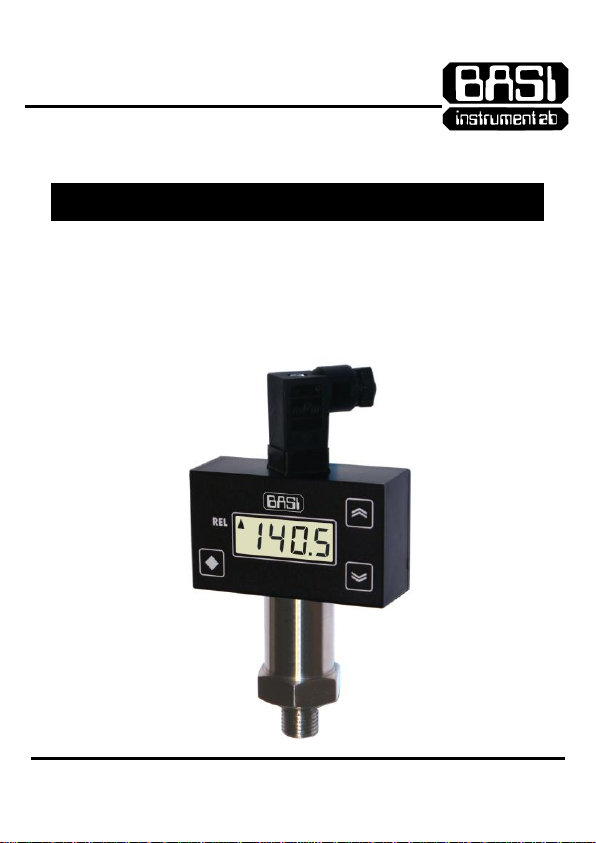
PRESSURE TRANSMITTER WITH DISPLAY
v1-2-03.13
BPT50-A
OPERATION MANUAL
Please read this Operation Manual before mounting and operating!
Save the Manual for future references!
Page 2
Overview
2
BPT50-A is a combination of a pressure
sensor and a programmable looppowered 5-digit LCD display that allows
visualization of the measured pressure
from -9999 to 9999 units. BPT50-A is also
equipped with a programmable pressure
alarm driving a low-power electronic relay
output which can also be used to activate
various electric actuators for ON/OFF
pressure control.
Mounting and Wiring
Important note:
If the medium temperature
is higher than the maximum,
specified for your transmitter,
mount an additional
cooling spiral tube between
the object and the transmitter
in order to decrease
the medium temperature
at the transmitter input.
Mounting
Screw the BPT50-A transmitter to its
exact place using a preinstalled bush
with a female thread matching
the transmitter's one (¼", ½", etc.).
To ensure hermetical mounting,
use a proper gasket (e.g. DIN16258).
The right tightening torque depends
on the gasket material and shape
as well as on the mounting thread.
For mounting, use ONLY a proper
hexagonal wrench applying the torque
ONLY to the hexahedral transmitter head!
The installation site must be
protected from deep-freezing
and high-temperature sources, and
all environmental conditions must be
within those, specified for your
transmitter type (see 'Specifications').
Wiring
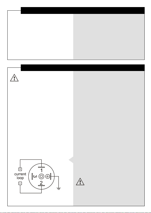
Connect the transmitter via detachable
connector Mini-HIRSCHMAN by following
the markings as shown on the left.
Important note:
The supply voltage must be
greater than the required minimum
(marked on the label) plus
the load voltage drop at 20 mA!
Page 3
Parameter Programming
3
Some parameters
are accessible only
when the respective
functionality is installed.
(see 'Specifications').
- Changing
Point Position value
reflects on the real value
of all parameters
with ISU!
E.g.: changing
Point Position value
from (0) to (0.0)
would change
a Set-point value
of 100 to 10.0!!!
Device parameters
BPT50-A is a programmable device whose
service behavior is determined by a set
of parameters. All the parameters, along
with their names, symbols, and value ranges,
are given in Table 1.
Setting numerical parameter value
Enter parameter value adjustment mode
(see 'Program Levels').
The whole part of the value together with
the left zeroes appears on the display,
and the rightmost digit blinks.
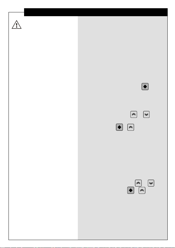
To select another digit, press .
The 4 rightmost digits can accept values
from 0 to 9, and the leftmost digit
can accept the value - or none.
To increase or decrease the blinking digit
value, use respectively or .
Confirm the adjusted value by pressing
simultaneously + .
If the new value has not been confirmed
and no key has been pressed for a certain
period of time, value adjustment
automatically ceases, and the parameter
retains its initial value.
Setting symbolic parameter value
Enter parameter value adjustment mode
(see 'Program Levels').
Read the blinking parameter value.
To change the value, use or ,
and to confirm, press + .
If the new value has not been confirmed
and no key has been pressed for a certain
period of time, value adjustment
automatically ceases, and the parameter
retains its initial value.
Page 4
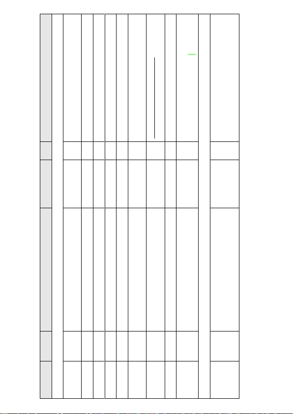
Table 1
Notes
Configuration Parameters
when indicating values
with the input-signal measurement unit (ISU)
display offset value
higher value for better filtration
For authorized personnel ONLY!
DO NOT SET to YES!
++L_ - activates under set point,
_V++- activates over set point
Keyboard Locking Parameter (parameter of Hidden level)
d"EY (keyboard disabled),
ESP (only set-point adjustment enabled),
E"EY (keyboard enabled)
Unit
-
ISU
ISU
ISU
- - ISU
-
-
Value
0, 0.0, 0.00, 0.000
-9999 ... 9999
-9999 ... 9999
-9999 ... 9999
0…255
0…3000
no, YES
-9999 ... 9999
++L_, _V++
d"EY,
ESP,
E"EY
Description
Display decimal point position
Display value at low limit of the input range
Display value at high limit of the input range
Constant to be added to the measured input value
Relative time constant of the input filter
Zone around the measured value,
within which the filter is active
Enables / disables calibration mode.
Set-point value of the alarm output
Control action direction of the alarm output
Keyboard locking mode
Symbol
Pnt
ILo
IHi
oFFS
\t
\b
cALE
SP1
dir1 Loc"
Parameter
Point Position
Display Low
Display High
Display Offset
Filter Time
Filter Band
Calibration
Set Point
Direction
Lock
Keyboard
Page 5
Program Levels
5
Programming order
Unlock the keyboard.
Adjust the configuration parameters.
If needed, restrict the access again
by adjusting the Lock Keyboard parameter.
Access control (Hidden level)
Hold
depressed while turning
the power supply on and until
Loc" appears.
Set keyboard locking mode
according to Table 1.
Basic level
At power-on, BPT50-A enters Basic level.
At this level, the device indicates
the measured pressure with a resolution,
according to the Point Position parameter.
If the measured value is greater than
Display High + 10, the display shows
blinking error message {++}.
When the measured value is less than
Display Low - 10, L__V is displayed.
Either error message may appear
on the display also as a result
of a damaged sensor.
Configuration level
Enter from Basic level by pressing
and holding until conF appears
on the display.
Choose a parameter using or
.
To enter parameter value
adjustment mode, press .
If no key has been pressed for a while,
the device automatically returns
to Basic level, storing all confirmed
changes.
For quick exiting and saving,
use key combination + or
select rtn and press .
Page 6
Output Control
6
Alarm output operation
The alarm output operates
according to the control
algorithm parameters.
The sign in the upper left
display corner indicates
activated alarm output.
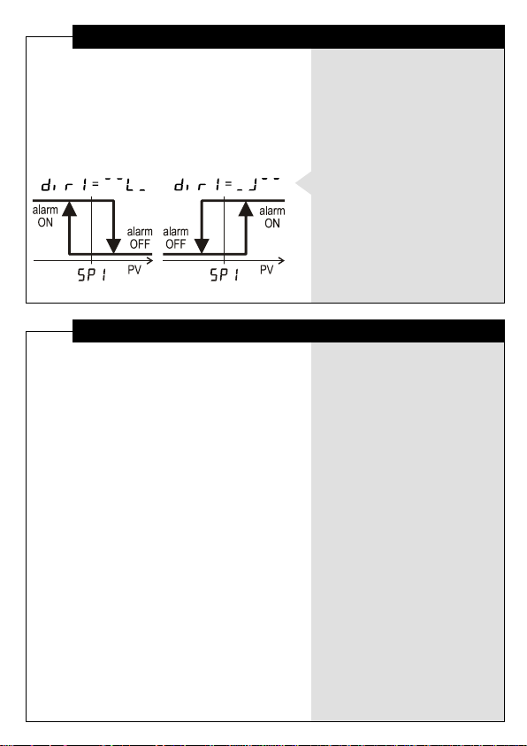
ON/OFF control algorithm
The static characteristic
of an alarm relay controlled
by an ON/OFF algorithm
is shown on the left drawing.
Input Filtration
Low-pass filter
This first-order filter acts
ONLY within a certain band
around filter output value.
This has been designed
to cut periodic noises
outside the communication
signal spectrum.
Filter operation is defined
by two parameters:
Filter Time (defines filter time
constant) and Filter Band
(defines filter active band
around filter output value).
If the newly measured value
differs from the filter output
by more than Filter Band,
the filter resets with a new
initial output value
(newly measured value).
Page 7

Waste Disposal
7
Do not dispose of
electronic devices
together with
household waste
material!
If disposed of within European Union,
this product should be treated
and recycled in accordance with the laws
of your jurisdiction implementing
the WEEE Directive 2002/96
on the Waste Electrical and Electronic
Equipment.
Page 8

Specifications
8
Pressure Range
Output Signal
Alarm Output
Power Supply UB
Voltage Deviation
Loop Voltage Drop
Maximum Line Load
Medium Temperature
Ambient Temperature
Sensor Accuracy
Display Error
Sensor Temperature Drift
Display Temperature Drift
Response Time
Overload
Process Connection
Protection Class: sensor / display
.......................... bar
4…20 mA, 2-wire
SSR 0.12A/240V, MOS gate 0.1A/60V
16…32 VDC, ...............................
2% at 50/60 Hz
max. 6 V
RA[] = (UB[V] - 14 V) / 0.02 A
-30…85 °C
-20…70 °C
1.0% (at medium temperature 10...40 °C)
0.1% from span
0.02% from span for 1 °C
0.01% from span for 1 °C
10 ms (0...99% of span)
1.5 x full span
G¼", G½", ¼" NPT, ½" NPT,
....................................
IP65 / IP44
Warranty and Support
………………………….
serial number
………………………….
manufacturing date
QC check mark …….……(passed)
(stamp)
BASI Instrument AB
p.o.box 53
SE-275 06 VOLLSJÖ, SWEDEN
tel: +46 (0)40 88009
fax: +46 (0)40 929877
e-mail: [email protected]
QD-8.2.4-WC
Warranty
BASI Instrument AB warrants this product
to be free from defects in materials
and workmanship for 2 years. If your unit
is found to be defective within that time,
we will promptly repair or replace it.
This warranty does not cover accidental
damage, wear or tear, or consequential
or incidental loss. This warranty
does not cover any defects caused
by wrong transportation, storage, installation,
or operating (see 'Specifications').
Technical support
In the unlikely event that you encounter
a problem with your BASI device,
please call your local dealer or contact
directly our support team.
 Loading...