

Page 1

INSTALLATION MANUAL
Residential and Small
Commercial Applications
Page 2

Page 3

WATERTEC™ S100 INSTALLATION MANUAL
Congratulations on selecting the WaterTec™ S100 kit, the industry’s
leading soil-moisture sensing unit for residential and small commercial
applications.
The following manual will guide you step-by-step through the installation
process. Pages 11-17 contain troubleshooting steps to further assist in
your installation. Additional information can be found online at
www.baselinesystems.com
Before You Get Started .............................................................................................3
S100 Operational Features.......................................................................................4
Step 1 - biSensor Placement ....................................................................................5
Step 2 - Determining Your Wiring Configuration.....................................................6
Option A - Valve Common Interrupter .....................................................6
Option B - Drip Bypass ...............................................................................6
Step 3 - Install and Wire S100....................................................................................7
Step 4 - Setup Sprinkler Timer and Set Cycle Window...........................................7
Step 5 - Connect the biSensor.................................................................................7
Step 6 - biSensor Installation.....................................................................................8
Step 7 - Verify All Connections.................................................................................9
Step 8 - 24-hour Moisture Threshold Calibration.....................................................9
Future Adjustments..................................................................................................10
How to Get a Beautiful Lawn.................................................................................10
Troubleshooting for Initial Installation ...............................................................11-12
Operational Troubleshooting & Adjustments .......................................................12
Troubleshooting Lawn Conditions....................................................................13-14
Troubleshooting Error Codes ..................................................................................17
Before You Get Started
Read the entire manual before starting
Before installing your new WaterTec S100, operate the sprinkler system to ensure the system
is functioning properly and all heads are properly adjusted. For best results you will need
to know the distribution rate of your sprinklers as this usually varies greatly from zone to
zone. Ideally each zone would receive the same amount of water (1/2” to 3/4”). Baseline
recommends that, prior to installation, you replace any back-up batteries your timer
requires. You may need to refer to the original owner’s manual.
WaterTec S100 Manual Aug06 Rev. 1
www.baselinesystems.com • (866) 294-5847
© Copyright 2006, Baseline, LLC All Rights Reserved
™
WaterTec
,
biSensor
™
and
™
biLine
are trademarks of Baseline, LLC.
3
Page 4

www.baselinesystems.com
www.baselinesystems.com
www.baselinesystems.com
+
+
Valve
Valve
Valve
Active
Active
Active
Allow
Allow
Allow
Water
Water
Water
D
+
Moisture Threshold/
Moisture Threshold/
Moisture Threshold/
E
Cycle Window
Cycle Window
Cycle Window
-
-
-
A B C D E F
A B C D E F
A B C D E F
H
A - 24 VAC
A - 24 VAC
A - 24 VAC
B - 24 VAC
B - 24 VAC
B - 24 VAC
C - Interrupt 1
C - Interrupt 1
C - Interrupt 1
D - Interrupt 2
D - Interrupt 2
D - Interrupt 2
E - Common
E - Common
E - Common
F - Sensor
F - Sensor
F - Sensor
Soil Moisture
Soil Moisture
Soil Moisture
Sensor Update
Sensor Update
Sensor Update
Hold to adjust Threshold
Hold to adjust Threshold
Hold to adjust Threshold
Bypass (allow water)
Bypass (allow water)
Bypass (allow water)
Hold to adjust Cycle Window
Hold to adjust Cycle Window
Hold to adjust Cycle Window
A
B F
C G
Operational Features
A Soil Moisture: Water content present in the soil
• Value is displayed by default when no buttons are pressed or held.
• Soil moisture level is displayed as volumetric, ranging from 0.0 to 50.0.
B Sensor Update:
• Brief button press: Causes the biSensor to take a moisture reading.
• Hold button: Displays current Moisture Threshold value. See below for
operation.
C Bypass: Allows the sprinkler timer to operate without interruption from the
S100. Bypass mode is indicated by a periodic flashing of “OFF” on the S100
display.
• Brief button press: Toggle the Bypass function. When enabled the Allow
Water light should turn on.
• Hold button: Holding the Bypass button for 2 seconds displays the current
Cycle Window duration. Use (+)/(-) buttons while holding Bypass to change
the Cycle Window to a value between 0 and 24 hours. Default is 12 hours.
D Moisture Threshold: Soil moisture value at which the S100 will allow watering.
• While “Sensor Update” button is being held, use (+)/(-) buttons to change
the moisture threshold.
E Cycle Window: The cycle window is the time allowed to complete a water
cycle once your soil moisture has reached your soil moisture threshold.
F Valve Active: This light indicates that the valve the biSensor is attached to
is currently active (watering).
G Allow Water: This light indicates that the S100 is allowing your sprinkler timer
to water based upon its user defined settings (the system will begin watering
at the next start time programmed on the sprinkler timer).
H Wire Harness: Wires are attached from the sprinkler timer to the S100 here.
Setup Operations: Calibration Cycle
(for initial installation or biSensor repositioning
• Hold the (+)(-) and (Bypass) buttons simultaneously for 3 seconds. The screen
will flash between “CAL” “24 H” and the current moisture reading. The “24
H” will count down on the hour until the calibration is complete. Watering
is paused during this time.
Communication Test: The S100 communicates with the biSensor for about two
minutes, checking for any potential errors
.
• Hold the (+)(-) and (Sensor Update) buttons simultaneously for 3 seconds.
For more information, see Step 1 on page 15 in the Troubleshooting section.
4
WaterTec S100 Manual Aug06 Rev. 1
)
Page 5

Step 1 biSensor Placement
When planning the biSensor location, take into account variables such as
distribution rate, sun exposure and soil type, or other site specific characteristics
that may affect water holding capacity or the rate at which plants use water.
The location of the biSensor will determine how frequently your sprinkler system
is allowed to water.
than average it will cause your system to operate less frequently, possibly causing
dry spots. If the biSensor is placed in an area that receives less than average
water it will cause the system to operate more frequently.
Baseline biSensor placement recommendations:
• Place the biSensor near the center of a zone (should only receive water
from one zone).
• Place the biSensor in an area that receives average to slightly below average
water.
• Keep away from sidewalks and driveways to avoid water from car washing
or other factors.
If the biSensor is placed in an area that is generally wetter
The illustration to the
right identifies heavy
shadow and runoff
areas in Red and
ideal locations in
Light Green. Avoid
Red areas when
installing your
biSensor. Dark
Green areas with
some shadow can
be used as a
secondary location.
SENSOR
LOCATION
SECONDARY
LOCATION
SENSOR
LOCATION
SENSOR LOCATION
SECONDARY
LOCATION
SENSOR
LOCATION
N
note
WaterTec S100 Manual Aug06 Rev. 1
Note: When installing the biSensor connect it to the most
convenient valve. This connection is used for communication.
5
Page 6
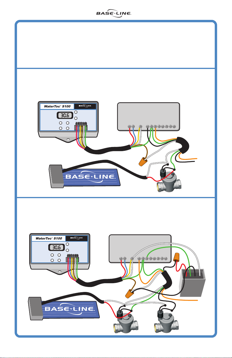
Step 2
Determining Your Wiring Configuration
Option A: This is the most common option and will work on any timer that has
an accessible 24VAC power source.
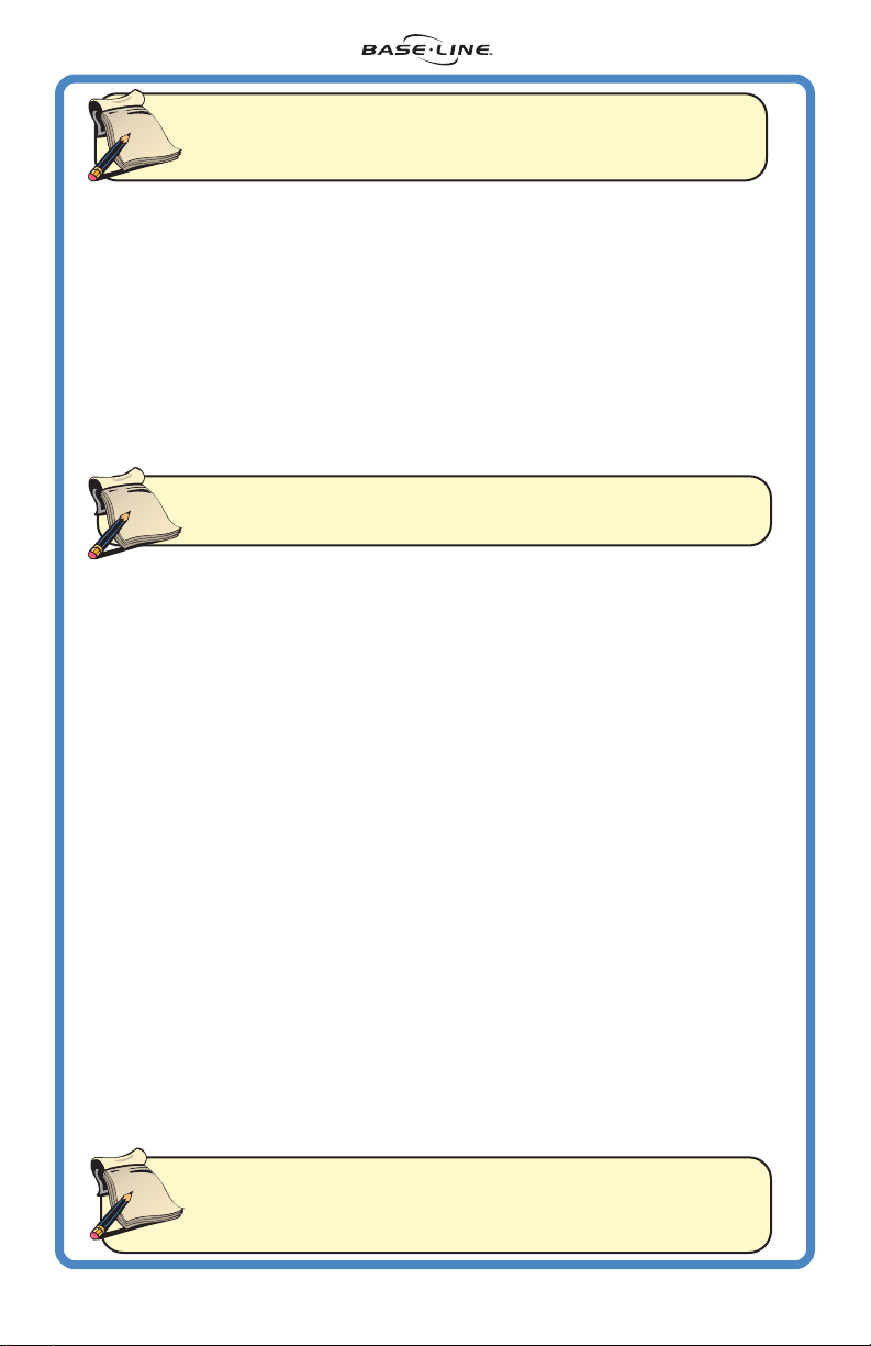
Option B: This option is used for systems with zones requiring more frequent
watering than the biSensor controlled zones utilizing Baseline's Drip Bypass.
(DRIP BYPASS SOLD SEPARATELY)
Option A
Connect wires A and B (red and blue) to the 24V connectors on the sprinkler timer
Connect wires C and E (yellow and white) to the common on the sprinkler timer
Connect wire D (brown) to the valve common
Connect wire F (green) to the valve with the sensor
Soil Moisture
Soil Moisture
Soil Moisture
Bypass (allow water)
Bypass (allow water)
Bypass (allow water)
Hold to adjust Cycle Window
Hold to adjust Cycle Window
Hold to adjust Cycle Window
Valve Common Interrupter
www.baselinesystems.com
www.baselinesystems.com
www.baselinesystems.com
+
+
+
Moisture Threshold/
Moisture Threshold/
Moisture Threshold/
Cycle Window
Cycle Window
Cycle Window
-
-
-
A - 24 VAC
A - 24 VAC
A - 24 VAC
B - 24 VAC
B - 24 VAC
B - 24 VAC
A B C D E F
A B C D E F
A B C D E F
C - Interrupt 1
C - Interrupt 1
Sensor Update
Sensor Update
Sensor Update
Hold to adjust Threshold
Hold to adjust Threshold
Hold to adjust Threshold
Valve
Valve
Valve
Active
Active
Active
Allow
Allow
Allow
Water
Water
Water
C - Interrupt 1
D - Interrupt 2
D - Interrupt 2
D - Interrupt 2
E - Common
E - Common
E - Common
F - Sensor
F - Sensor
F - Sensor
SPRINKLER TIMER
24V COM 1 2 3 4 5 6 7 8
Connect sensor wires across valve solenoid.
Option B
Connect wires A and B (red and blue) to the 24V connectors on the sprinkler timer
Connect wires C and E (yellow and white) to the common on the sprinkler timer
Connect wire D (brown) to the valve common
Connect wire F (green) to the valve with the sensor
Soil Moisture
Soil Moisture
Soil Moisture
Sensor Update
Sensor Update
Sensor Update
Hold to adjust Threshold
Hold to adjust Threshold
Hold to adjust Threshold
Bypass (allow water)
Bypass (allow water)
Bypass (allow water)
Hold to adjust Cycle Window
Hold to adjust Cycle Window
Hold to adjust Cycle Window
Drip Bypass
www.baselinesystems.com
www.baselinesystems.com
www.baselinesystems.com
+
+
+
Moisture Threshold/
Moisture Threshold/
Moisture Threshold/
Cycle Window
Cycle Window
Cycle Window
-
-
-
A - 24 VAC
A - 24 VAC
A - 24 VAC
B - 24 VAC
B - 24 VAC
B - 24 VAC
A B C D E F
A B C D E F
A B C D E F
C - Interrupt 1
C - Interrupt 1
Valve
Valve
Valve
Active
Active
Active
Allow
Allow
Allow
Water
Water
Water
C - Interrupt 1
D - Interrupt 2
D - Interrupt 2
D - Interrupt 2
E - Common
E - Common
E - Common
F - Sensor
F - Sensor
F - Sensor
SPRINKLER TIMER
24V COM 1 2 3 4 5 6 7 8
Connect sensor wires across valve solenoid.
6
WaterTec S100 Manual Aug06 Rev. 1
Page 7

Step 3
SEN 24V COM 1 2 3 4 5 6 7 8
SPRINKLER TIMER
Valve
Active
Allow
Water
www.baselinesystems.com
Moisture Threshold/
Cycle Window
A - 24 VAC
B - 24 VAC
C - Interrupt 1
D - Interrupt 2
E - Common
F - Sensor
A B C D E F
+
-
Valve
Active
Allow
Water
www.baselinesystems.com
Moisture Threshold/
Cycle Window
A - 24 VAC
B - 24 VAC
C - Interrupt 1
D - Interrupt 2
E - Common
F - Sensor
A B C D E F
+
-
Valve
Active
Allow
Water
www.baselinesystems.com
Moisture Threshold/
Cycle Window
A - 24 VAC
B - 24 VAC
C - Interrupt 1
D - Interrupt 2
E - Common
F - Sensor
A B C D E F
+
-
Install and Wire the S100
1. Strip the provided harness wire and connect to wire harness
as shown: red, blue, yellow, brown, white and green (from
left to right). Plug the harness into the S100.
2. At this point also strip the biSensor wire providing enough
exposed wire to connect to desired valve.
3. Mount the S100 near your sprinkler timer.
The S100 is not
weatherproof.
4. Wire the S100 using the option chosen in Step 2. Using your
sprinkler timer, manually run all zones to ensure that the connections are solid.
Step 4 Setup Sprinkler Timer
and Set Cycle Window
1. Set your sprinkler timer to apply 1/2”
to 3/4” of water to each zone each
day. This will allow the in-ground
moisture biSensor to choose the best
possible days to water. For instructions
on how to check distribution rate, see
Step 2 on page 15 of the Troubleshooting section. (If needed, refer to the sprinkler
timer’s manual for operational instructions).
2. The cycle window is the time allowed to complete a water cycle once your
soil moisture has reached your moisture threshold. The S100 comes preset with
a 12 hour window. This works well for most applications and there may be no
need to re-set this value.
Reasons to re-set the cycle window
• If your system needs more than twelve hours to complete a watering cycle
once the biSensor zone has been watered.
• If you choose to water your lawn several times per day (this can result in poor
root development).
To set the cycle window hold the “Bypass” button for 2 seconds. This will display
the current cycle window. Use (+)/(-) buttons while holding the “Bypass” button
to change the cycle window to a value between 0 and 24 hours.
:
Step 5
Connect the biSensor
NOTE: It is very important that you use waterproof connectors after all connections
have been verified in Step 7.
1. Before burying the biSensor, verify communications by pressing the “Sensor
Update” button. A numeric reading indicates success. A display of Er1 or Er2
indicates a wiring error. Consult the Troubleshooting section on pages 11-12.
2. Manually run the station to which you connected the biSensor to verify
connection.
3) Once connections have been verified, disconnect the biSensor from the valve
as this simplifies burial.
WaterTec S100 Manual Aug06 Rev. 1
7
Page 8

Step 6
biSensor Installation
The biSensor has several burial requirements.
There must be good contact between the soil
and the biSensor, and it needs to be buried lying
on its side. If buried flat, the biSensor readings
can be wrong due to moisture pooling on the
surface of the biSensor. The biSensor should be
buried 4” to 6” inches deep in turf areas and
deeper for planters and tree areas (root zones).
Note: Ensure biSensor is buried 4”-6”
note
below grass line for optimal
readings. This depth also prevents
future damage, i.e., aerators, etc.
(Option A)
1. Using a shovel or edger cut out a piece of
sod approximately 1-foot long by 6-inches
wide in the area where you plan to bury
the biSensor.
2. Carefully remove the sod and try to keep the
roots intact.
3. Dig a small trench the length of the biSensor
in the exposed dirt.
4. Insert the biSensor into the trench, burying it
on its long edge. If buried flat, biSensor
readings can be wrong due to moisture
pooling on surface of the biSensor.
5. Remove any rocks or gravel that are touching
the surface of the biSensor to ensure there
are no air pockets.
6. Cut a slit back to the valve box for the
communication wires. Take care to bury
them deep enough to avoid damage from
aeration or other activities.
7. Using a bucket of water saturate the soil
surrounding the biSensor and compact the
soil around it tightly.
8. Refill hole, replace sod and saturate the area
thoroughly. Once saturated, compact soil
firmly around the biSensor. The biSensor must
make good contact with the surrounding soil.
OPTION A
Dig 6”X12”
Dig 6”X12”
section and ...
section and ...
Re-cover area and
Re-cover area and
heavily saturate with water.
heavily saturate with water.
OPTION B
Cut slit into grass
Cut slit into grass
then work shovel
then work shovel
back and forth to
back and forth to
create a slot for the biSensor
create a slot for the biSensor
peel back sod
peel back sod
with roots intact.
with roots intact.
Bury biSensor
Bury biSensor
4” TO 6” deep
4” TO 6” deep
about 12” long
about 12” long
by 6” deep...
by 6” deep...
Bury biSensor
Bury biSensor
4” TO 6” deep
4” TO 6” deep
(Option B)
1. With a flat blade shovel, cut a slit in the grass
where the biSensor will be placed. Widen
slit with a back and forth motion.
Re-cover area and
2. Place the biSensor in the slit horizontally so
the top of the biSensor is 4”-6” deep.
Re-cover area and
heavily saturate with water.
heavily saturate with water.
3. Remove any rocks or gravel that are touching
the biSensor to ensure there are no air pockets.
4. Cut a slit back to the valve box for the communication wires. Take care to
bury them deep enough to avoid damage from aeration or other activities.
5. Using a bucket of water saturate the soil surrounding the biSensor and compact
the soil around it tightly.
8
WaterTec S100 Manual Aug06 Rev. 1
Page 9
note
Note: It is critical that the soil is well saturated with water, otherwise the
moisture threshold calibration in Step 8 will fail. It is also important that
you complete Step 8 within one hour of saturating soil.
Step 7
Reconnect biSensor to desired valve. Verify that all connections are functioning
properly after the biSensor has been buried.
1. Verify communications with biSensor by pressing the “Sensor Update” button.
A numeric reading indicates success. A display of Er1 or Er2 indicates a wiring
error. Consult the Troubleshooting section on page 11-12 if you receive an
error.
2. If the numeric reading is below 20, the biSensor has excessive air pockets
around it. If this occurs, rebury the biSensor as per Step 6 taking extra care
to ensure the soil is well compacted around the biSensor.
3. Manually run the station connected to the biSensor. This will verify connection.
note
Step 8
The S100 comes with an auto-calibration capability that will set the moisture
threshold based on your soil type. This is useful for new installations. Before running
the moisture threshold calibration; ensure that the soil around the biSensor is
heavily saturated with water as instructed in Step 6. If not properly saturated,
the calibration will fail. Write down the current date, time and sensor reading to
be used as a reference point.
Date ________________ Time ____________ Sensor Reading _________________
1. Hold the (+)(-) and (Bypass) buttons simultaneously for 3 seconds. The screen
will flash between “CAL” “24H” and the current moisture reading. The “24H”
will count down on the hour until the calibration is complete. Watering is
paused during this time. It is important that the biSensor does not receive any
water during calibration. This process will fail or provide false feedback if it
does.
2. If the calibration succeeds, the moisture threshold will be automatically set,
and the system will allow watering when soil moisture drops below this
threshold.
If an error occurs during calibration, the screen will flash “Er3” indicating calibration
failed, and then another “Er#”. This # represents the reason for failure. See
Troubleshooting for information on the various error messages. The S100 will need
to be re-calibrated. In addition, in the event of a failure, the S100 will go into
“bypass” mode allowing for normal timer-based watering.
Verify All Connections
Note: All connections need to be water-tight. There are several products
on the market that will accomplish this. Follow the manufacturer’s
instructions for the product you choose.
24 Hour Moisture Threshold Calibration
Note: If you need to exit this mode early, hold the ”Sensor Update” button for
3 seconds.
Note: If the biSensor receives water during this 24 hour period, or was
note
WaterTec S100 Manual Aug06 Rev. 1
not saturated during Step 6, the calibration will either fail entirely
or set an incorrect threshold for your lawn. If this happens, you
will need to resaturate the soil and restart Step 8.
9
Page 10

Future Adjustments
Manual Threshold Adjustment As the grass roots grow back around the
biSensor, the threshold may need to be adjusted. Observe lawn conditions
and then adjust the threshold as needed. To manually adjust your moisture
threshold begin by taking a biSensor reading (after a watering cycle) by
pressing the “Sensor Update” button. Next set your threshold slightly above
or below this value (An adjustment of 0.1 – 0.2 points is all that should be
necessary).
• Raising the threshold will result in more frequent watering.
• Lowering the threshold will result in less frequent watering.
Automatic Moisture Threshold Calibration If you need to re-calibrate your
moisture threshold, simply begin by re-saturating the ground surrounding the
biSensor. The dirt surrounding the biSensor needs to be holding as much
water as it can, it may take a few applications of water to accomplish this.
Once saturated, repeat Step 8 of this manual to automatically calibrate
your moisture threshold.
How to Get a
Beautiful Lawn
Watering SMART is a critical
step towards a beautiful and
healthy lawn.
Water Less Frequently
• Using the WaterTec to
determine which days to water
will promote deep roots and
will water only when needed,
conserving water (and saving
you money).
• Watering too often promotes
a shallow root structure and
washes nutrients from the roots.
Water Deeply
• Set your sprinkler timer to apply
1/2” to 3/4” of water
(determine water application
rate for each zone and
calculate the run time to apply
3/4” of water—use cups or
cans to catch water for a
fixed time to determine
application rate). Each zone
could have a different water
run time.
10
WaterTec S100 Manual Aug06 Rev. 1
Page 11

Troubleshooting for Initial Installation
Problem Cause Solution
Er1 is displayed The S100 cannot communicate with
the biSensor
Er2 is displayed The S100 has detected excessive
current while trying to communicate
with the biSensor
Er3 is displayed
along with
another error
Er4 is displayed
(this is a warning
message,
pressing”Sensor
Update”will
There was a problem during the S100
24-hour moisture threshold
calibration
Unexpected reading during 24-hour
moisture threshold calibration, final
reading was not substantially
different from first
(please refer to
the Er4 code on page 17)
clear this)
Er5 is displayed An interruption of the 24-hour
moisture threshold calibration
occurred due to attempted valve
activation
Er6 is displayed
Display is blank.
LED’s are off
Display flashes
random
segments
or 88.8
Unexpectedly low reading during 24hour moisture threshold calibration
S100 is not receiving 24 VAC • Make sure the 24VAC transformer
The S100 common is not connected
correctly
• Check the wiring and connections
to the biSensor
• Make sure the correct valve wire
and common wire are used
• After making repairs follow the
“Verify biSensor Communication”
instructions under Step 1 at the end
of this section
• Double-check the wiring and
connections to the biSensor
• Make sure the common and
biSensor wires are correctly
connected
• Check for a faulty valve solenoid
• After making repairs follow the
“Verify biSensor Communication”
instructions under Step 1 at the end
of this section
• This error is accompanied by one
of the other error codes
• Refer to the other Er# for possible
solutions
• Follow the instructions under Step
5 at the end of this section
• Make sure no extra water is
applied to the biSensor after
calibration starts or the S100 may
set a non-optimal threshold
• Check the valve the biSensor is
connected to for proper operation
• After making repairs follow the
instructions under Step 5 at the end
of this section (turn off controller
during 24-hour moisture threshold
calibration)
• Follow the instructions under Step
5 at the end of this section
is plugged in
• Check that the two 24VAC lines
and the common from the S100 are
wired correctly
• Make sure the common from the
S100 is connected to the valve
common of the sprinkler controller
WaterTec S100 Manual Aug06 Rev. 1
11
Page 12

Troubleshooting for Initial Installation
(continued)
Problem Cause Solution
The S100 flashes
"88.8" then fades
away
biSensor is
reading a value
under 20 when
soil appears wet
Controller does
not have
access to
24VAC
The controller sensor ports will not
support the S100
There may be air pockets around
the biSensor
Some older mechanical controllers • Some older sprinkler controllers
• Use the common interrupt
method to wire the S100
• Rebury the biSensor as per Step
6 on page 8. When reburying the
biSensor be especially careful that
there are NO rocks touching the
blade of the biSensor as this can
lead to false readings
do not have available access to
24VAC; for more information on this
go to www.baselinesystems.com
Operational Troubleshooting & Adjustments
Main Problem Specifics Solution
Er1 is displayed The S100 cannot communicate with
the biSensor
Er2 is displayed The S100 has detected excessive
current while trying to communicate
with the biSensor
Display is blank.
LED’s are off
There are
puddles forming
during irrigation
S100 is not receiving 24 VAC • Make sure the 24VAC transformer
• Check the wiring and
connections to the biSensor
• Connections need to be
waterproof and free of corrosion
• Check biSensor wires for damage
• Check biSensor for damage
• After making repairs follow the
“Verify biSensor Communication”
instructions under Step 1 at the end
of this section
• Double-check the wiring and
connections to the biSensor
• Verify connections inside valve
box are water tight
• Check for a faulty valve solenoid
• Check for lightning damage
is plugged in and receiving power
• Check that the two 24VAC lines
and the common from the S100
are wired correctly
• Follow the instructions under Step
6 at the end of this section
12
WaterTec S100 Manual Aug06 Rev. 1
Page 13

Troubleshooting Lawn Conditions
Use this diagram in reference to the zones in this Troubleshooting section
ZONE 1 ZONE 2
ZONE 3 ZONE 4
Lawn Condition Possible Causes Solution
Area around the
biSensor is dry
but the lawn is
wet
Area around the
biSensor is wet
but the lawn is
dry
Zone 1 is wet,
remaining lawn
is dry
Zone 1 is dry,
remaining lawn
is wet
Zones 1-3 have
adequate
water, Zone 4 is
drying out
Plugged head over biSensor
Broken or missing head near
biSensor
Object was placed over the
biSensor
Broken or leaky head near the
biSensor causing water to pool
around the biSensor
Broken line causing water to leak
into the soil surrounding the biSensor
Run time on zones 2-4 are too short
Cycle window is not long enough
Run time on zone 1 is too short
Disruption causing the valve to not
operate correctly
Check the area around the
biSensor. Fix any problems with the
irrigation system that would cause
the area around the biSensor to not
receive water. In addition remove
any obstructions that may have
been placed over where the
biSensor is buried
Replace or repair parts as needed
Check the distribution rate of zones
2-4 as per Step 2 on page 15. Adjust
the run time accordingly
Check the duration of your cycle
window. Refer to Step 4 on page 7
Check the distribution rate of zone
1 as per Step 2 on page 15. Adjust
the run time accordingly
Check the wiring between the valve
box and the valve. Make any
necessary repairs
WaterTec S100 Manual Aug06 Rev. 1
13
Page 14

Troubleshooting Lawn Conditions (continued)
Lawn Condition Possible Causes Solution
Entire lawn is
dry
Entire lawn is
too wet
biSensor is
receiving
adequate
water, other
areas are dry
biSensor is
receiving
adequate
water, other
areas are wet
Zones 1, 3 and 4
are receiving
adequate
water. Zone 2
has dry or wet
areas
System Malfunction
Run times on all zones are too short
Moisture Threshold is too low
Heavy rain fall immediately after or
during a watering cycle
Run times on all zones are too long
Moisture Threshold is too high
Water distribution is not uniform
biSensor is buried in an area that
receives above average watering
Water distribution is not uniform
biSensor is buried in an area that
receives significantlly below average
watering
Water distribution in zone 2 is not
uniform
Check the overall system functions.
Ensure the master valve is operating
correctly, that the system is not shut
down, etc...
Check the distribution rate of all
zones as per Step 2 on page 15.
Adjust the run times accordingly
Refer to Step 7 on page 17
N/A
Check the distribution rate of all
zones as per Step 2 on page 15.
Adjust the run time accordingly
Refer to Step 7 on page 17
Refer to Step 3 on page 15
Make sure the biSensor is placed
within an area that follows the
guidelines on page 5. If it does,
check to see if the biSensor is
receiving any water from an
alternative source (An example
being your neighbors sprinklers)
Refer to Step 3 on page 15
Make sure the biSensor is placed
within an area that follows the
guidelines on page 5. If it does,
check to see if the biSensor is not
receiving any water due to an
obstruction (For example a bush
obstructing a sprinkler head)
Refer to Step 3 on page 15
14
WaterTec S100 Manual Aug06 Rev. 1
Page 15

Step 1: Verify biSensor Communication
1) Push the “Sensor Update” button to verify communication. A numeric
value should appear. If an Er# appears refer to the Troubleshooting
section above.
2) Run a Communication Test: Hold (+)(-) and (Sensor Update) buttons
simultaneously for 3 seconds. This test will flash alternately between
“SEn” and “###.” ### will start at 100 then count down to 0, repeatedly
communicating with the biSensor. This process takes about two minutes.
3) When it finishes it will flash “Err” and a number which is the quantity of
errors it encountered in its attempts, 000 to 200.
the error type. This error count will stop displaying after 10 minutes.
Note: To exit this mode early press and hold the “Sensor Update” button for
3 seconds.
A reading of 000 is good, meaning there are no errors.
4
5) If an error is encountered in this step, it is either an Er1 or Er2. Refer to
the top of the Troubleshooting section for specific information.
6) Repair wires or connections.
7) Repeat Step 1.
Step 2: Check Distribution Rate by Zone
To check the distribution rate of your system use several flat bottom containers
placed randomly throughout the zone (tuna cans work well). Run the zone
for a period of time long enough to get a measurable amount of water in
each catch device. Use the formula below to calculate the new runtime.
Average amount in cans ____ (inches) ÷ Desired amount applied _____
(inches) x Time that zone operated during test____(minutes)= New runtime
____(minutes)
This number is not
Step 3: Check Distribution Uniformity by Zone
To check the distribution uniformity of your system use several flat bottom
containers placed randomly throughout the zone. Run the zone for a period
of time long enough to get a measurable amount of water in each catch
device. Compare the amounts in each device. Using this information, make
adjustments to the sprinkler system in order to get a more uniform water
distribution.
Step 4: Check Distribution Uniformity and Rate in the biSensor Zone
To check the distribution rate of the zone the biSensor is buried in, use several
flat bottom containers placed randomly throughout the zone (tuna cans
work well) making sure at least one catch device is placed directly above
the biSensor. Run the zone for a period of time long enough to get a
measurable amount of water in each catch device. Use this information to
determine the following:
• The biSensor is placed in an area receiving average to slightly below
average precipitation within the zone. This is an optimum location for
the biSensor.
• The biSensor is placed in an area that is generally wetter than average.
This will cause your system to operate less frequently, possibly causing
dry spots.
WaterTec S100 Manual Aug06 Rev. 1
15
Page 16

Step 4: Continued
• The biSensor is placed in an area that receives far less than average
water. This will cause the system to operate more frequently then
desired. If it is determined that the biSensor is not receiving an average
to slightly below average amount of water check the performance of
all the related system components:
- Check all sprinkler heads affecting the area to ensure they are
functioning properly.
- Check the valve operation to ensure that it is opening completely
and not limiting water flow and that it is shutting off completely.
- Check system and zone pressure – improper pressures can cause
distribution uniformity problems. Refer to the sprinkler head
manufacturer for specifications.
If all system components are functioning properly move the biSensor to a
more appropriate area and then refer to Step 5: Re-running a 24-hour moisture
threshold calibration.
Step 5: Re-running a 24-hour Moisture Threshold Calibration
1) Re-saturate the soil. This may take several applications of water to
ensure the water has penetrated to the level of the biSensor.
2) Compact the soil around and over the biSensor to ensure there are no
air pockets around the biSensor. The biSensor is very durable but some
care should be taken to not destroy the biSensor. Rock or gravel
touching the biSensor directly can also cause a false reading. It may
be necessary to remove any rocks that are in direct contact with the
biSensor.
3) Once you are sure there are no air pockets around the biSensor, take
a soil moisture reading by pushing the “Sensor Update” button. This
value will vary depending on soil type but should read above 20. A
lower reading may mean there are remaining air pockets or rocks
touching the biSensor.
4) Re-check area to ensure the biSensor location is still well saturated.
5) Run the 24-hour moisture threshold calibration: Hold the (+)(-) and
(Bypass) buttons simultaneously for 3 seconds. The screen will flash
between “CAL” “24H” and the current moisture reading. The “24H” will
count down on the hour until the calibration is complete. Watering is
paused during this time.
Step 6: Soak Cycles
Soak cycles allow the water to soak into the soil more efficiently, promoting
healthier roots and a better looking site. It also reduces the potential for
puddling and run-off, and allows the water to soak down to the biSensor,
giving more accurate and timely readings. Soak cycles should be extended
for sloped areas and denser soil types. When watering a site, it is important
to allow enough time for water to soak into the ground. Usually soak times
are about 3 times as long as run times. This means that if you run your sprinkler
system for 30 minutes, you allow 90 minutes for the water to completely soak
into the ground. Refer to the manual for your sprinkler timer for the best way
to set up soak cycles.
16
WaterTec S100 Manual Aug06 Rev. 1
Page 17

Step 7: Changing the Moisture Threshold
The S100 Moisture Threshold calibration calculates a threshold for an average
system. If the distribution uniformity at your site is above or below average it
may be necessary to adjust the threshold for fine tuning. It may also be
necessary once the roots have grown around the biSensor.
• While the “Sensor Update” button is being held, use (+)/(-) buttons to
change the moisture threshold.
• Raising the threshold will result in more frequent watering.
• Lowering the threshold will result in less frequent watering.
Note:
note
Moving the threshold more than 0.2 in every 3 water cycles
can cause erratic behavior.
Troubleshooting Error Codes
Er1: Communication Error
• Incorrect Wiring.
• Bad Connections.
• Damaged Wire.
Er2: Over Current
• Bad Valve Solenoid.
• Short Circuit Wires.
Er3: 24- hour Moisture Threshold Calibration Failed
• This error is accompanied by one of the other five error codes to indicate reason for failure.
Er4: Value Out of Range Warning
• This warning can occur only during 24-hour moisture threshold calibration, and indicates that
the biSensor readings fall outside of the expected range. This could be caused by failure
to saturate the soil with water in the beginning, or by accidental watering of the site after
calibration started. If an Er4 occurs the S100 will determine the best possible moisture
threshold based on the measured moisture values and allow the sprinkler system to water
based upon this setting.
Er5: Calibration Interrupted Error
• This error can occur only during 24-hour moisture threshold calibration and indicates that
something caused the calibration to be delayed too long, such as an open valve. Calibration
must complete within a certain amount of time from initial soil saturation to set a correct
threshold.
Er6: Low Reading During 24-hour Moisture Threshold Calibration Error
• This error can occur only during 24-hour moisture threshold calibration and indicates that
there was a low reading during calibration.
Step 5 on page 16
.
To resolve this, follow the instructions under
WaterTec S100 Manual Aug06 Rev. 1
17
Page 18

INSTALLATION NOTES:
18
WaterTec S100 Manual Aug06 Rev. 1
Page 19

Statement of Warranty
Baseline LLC warrants to the original consumer, purchaser that the
WaterTec S100 and associated biSensor will be free from defects in
material and workmanship for the period of one year from the installation
date.
This warranty is exclusive and in lieu of all others, whether oral or written,
expressed or implied. Baseline specifically disclaims any and all implied
warranties, including, without limitation, warranties of merchantability
and fitness for a particular purpose and against infringement. Baseline
is not responsible for special, incidental, indirect or consequential damages
resulting from any breach of warranty, or under any other legal theory,
including but not limited to loss of data, loss of profits, downtime, goodwill,
damage or replacement of equipment and property.
For warranty service, contact Baseline at 1-866-294-5847 to speak to a
customer support specialist. You must obtain a “Return Materials
Authorization (RMA)” number before returning a product.
Page 20

 Loading...