

Page 1

FGR2-PE Wireless Data Transceiver
Firmware 2.22
User Manual and Reference Guide
For use with Baseline Irrigaon Controllers
Part Number: LUM0024AB
Revision: A
Last Updated: 12/7/2011
Page 2

Safety Information
The products described in this manual can fail in a variety of modes due to misuse, age, or malfunction. Systems
with these products must be designed to prevent personal injury and property damage during product operation
and in the event of product failure.
Warning! Do not remove or insert diagnostics cable while circuit is live unless the area is
known to be free of ignition concentrations of flammable gases or vapors.
Warranty
FreeWave Technologies, Inc. warrants your FreeWave® Wireless Data Transceiver against defects in materials
and manufacturing for a period of two years from the date of shipment. In the event of a Product failure due to
materials or workmanship, FreeWave will, at its option, repair or replace the Product. The Product must be returned
to FreeWave upon receiving a Return Material Authorization (RMA) for evaluation of Warranty Coverage.
In no event will FreeWave Technologies, Inc., its suppliers, and its licensors be liable for any damages arising from
the use of or inability to use this Product. This includes business interruption, loss of business information, or other
loss which may arise from the use of this Product. Please be advised that OEM customer’s warranty periods may
vary.
Warranty Policy may not apply:
1. If Product repair, adjustments or parts replacements is required due to accident, neglect, unusual
physical, electrical or electromagnetic stress.
2. If Product is used outside of FreeWave specifications.
3. If Product has been modified, repaired, or altered by Customer unless FreeWave specifically
authorized such alterations in each instance in writing. This includes the addition of conformal coating.
Special Rate Replacement Option
A special rate replacement option is offered to non-warranty returns or upgrades. The option to purchase the
replacement unit at this special rate is only valid for that RMA. The special replacement rate option expires if not
exercised within 30 days of final disposition of RMA.
Restricted Rights
Any product names mentioned in this manual may be trademarks or registered trademarks of their respective
companies and are hereby acknowledged. Information in this manual is subject to change without notice and is
proprietary and confidential to FreeWave Technologies, Inc..
This manual is for use by purchasers and other authorized users of FreeWave® tranceivers.
No part of this manual may be reproduced or transmitted in any form or by any means, electronic or mechanical, or
for any purpose without the express written permission of FreeWave Technologies, Inc.. FreeWave reserves the
right to make changes to this manual without notice. Unless otherwise agreed to in writing,FreeWave assumes no
responsibility or liability for the use of this manual or the infringement of any copyright or other proprietary
right.FreeWave shall deem nothing contained in this manual as warranty or guarantee.
FreeWave's Wireless Data Transceivers are designed and manufactured in the United States of America.
FreeWave Technologies, Inc.
1800 South Flatiron Court
Boulder, CO 80301
303.444.3862
Toll Free: 1.866.923.6168
Printed in the United States of America.
Copyright © 2011 by FreeWave Technologies, Inc. All rights reserved. www.freewave.com
303.786.9948
LUM0024AB Rev A ii
Page 3

This product is licensed by The United States. Diversion contrary to U.S. law is prohibited. Shipment or reexport of this product outside of The United States may require authorization by the U.S. Bureau of Export
Administration. Please contact FreeWave Technologies, Inc. for assistance and further information.
UL Specifications
The FGR2-PE transceiver is suitable for use in Class I, Division 2, Groups A, B, C, and D or non-hazardous
locations only.
Warning! Explosion Hazard! Substitution of components may impair suitability for Class I,
Division 2.
The diagnostics port and cable do not have a latching connector and cannot be used in a hazardous location.
Important: UL approved devices must be connected to a Class 2 power source.
LUM0024AB Rev A iii
Page 4

FCC Notifications
This device complies with part 15 of the FCC rules. Operation is subject to the following two conditions: 1) This
device may not cause harmful interference and 2) this device must accept any interference received, including
interference that may cause undesired operation.
This device must be operated as supplied by FreeWave Technologies, Inc.. Any changes or modifications made to
the device without the express written approval of FreeWave Technologies, Inc. may void the user's authority to
operate the device.
Warning! The FGR2-PE has a maximum transmitted output power of 1 W. It is
recommended that the transmit antenna be kept at least 23 cm away from nearby persons
to satisfy FCC RF exposure requirements.
Whenever any FreeWave Technologies, Inc. module is placed inside an enclosure a label must be placed on
the outside of that enclosure which includes the module's FCC ID.
GNU Notification
Some of the software in the firmware is licensed under the GNU General Public License and other Open
Source and Free Software licenses. You can obtain corresponding source by contacting FreeWave and
requesting the source on CD.
LUM0024AB Rev A iv
Page 5

Document RevisionHistory
Date Rev Letter Updates Made
12/07/2011 A Updates include but are not limited to:
l Document is now broken into chapters and a series of appendices to help
make information easier to file. See the table of contents.
l All parameters that are available to set are listed in alphabetical order in
their respective chapters. Each parameter is also listed in the added index.
l Firmware revision information is available in Appendix A.
l Discovery Server procedures are now in Appendix C.
l Added Windows 7 instructions for changing an IP address.
l Added Tool Suite procedures where appropriate throughout.
l Converted to the current FreeWave look and feel.
LUM0024AB Rev A v
Page 6

LUM0024AB Rev A vi
Page 7

Table Of Contents
Chapter 1: Introduction 1
Getting to Know Your Plus-Style Transceiver 1
Boot-Up LED Sequence 2
Ethernet Port Conditions 2
Error LED Conditions 3
Com Port LED Conditions 3
Choosing a Location for the Transceivers 3
Choosing Point-to-Point or Point-to-MultiPoint Operation 3
Chapter 2: Setting Up and Programming Transceivers 7
Basic Steps to Programming Plus-Style Transceivers 7
MultiPoint Network Considerations 8
Powering the Transceiver 8
Determining and Setting a Transceiver's IP Address 9
Using HyperTerminal 9
Using Discovery Server 14
Resetting Transceivers to the Factory Default Settings 15
ConfigurationTool Options 16
Reading Plus-Style Transceivers in Tool Suite 18
Accessing Configuration Web Pages 19
Navigating the Web Pages 19
Providing Site Information 20
Using the MultiPoint Gateway to Change All Connected Transceivers 21
Creating User Logins 22
Defining User Groups 22
Adding and Deleting Users 23
Changing User Passwords 24
Upgrading Plus-Style Transceiver Firmware Using TFTPServer 24
Before You Get Started Upgrading Firmware Using the TFTPServer 25
Configuring the TFTP Server 25
Upgrading Firmware Using the Web Configuration Pages 26
Upgrading Plus-Style Firmware Globally 27
Verifying Firmware Upgrades 28
Common Firmware Upgrade Issues and Solutions 28
Chapter 3: IP and Network Communication Settings 31
LUM0024AB Rev A vii
Page 8

IP Parameter Reference 31
Default Gateway 32
IP Address 32
NTP Client Enable 33
NTP IP Address 33
Push to Syslog Server 33
Spanning Tree 33
Subnet Mask 34
Syslog Server 1 34
Syslog Server 2 34
VLAN Data ID 35
VLAN Default Gateway 35
VLAN IP Address 35
VLAN Management ID 35
VLAN Mode 36
VLAN Subnet Mask 36
Web Page Port (http) 36
Chapter 4: Serial Port Settings 39
Setting a Serial Port's Mode 39
Disabling Serial Ports 40
Using the Serial Port as an Alarm Client 41
Viewing a Serial Port's Status 41
Ethernet (Rx and Tx) 42
Serial (Rx and Tx) 42
Status 42
Serial Port Parameter Reference 42
Alarm IP & Port 42
Alarm Retry Limit (Attempts) 43
Drop Link 43
Multicast IP 43
Multicast Port 44
Serial Baud Rate 44
Serial CD Mode 44
Serial Data Bits 45
Serial Flow Control 45
Serial Interface 45
LUM0024AB Rev A viii
Page 9

Serial Modbus RTU 45
Serial Parity 46
Stop Bits 46
TCP Client Enable 46
TCP Client IP 47
TCP Client Port 47
TCP Server Enable 47
TCPServer Inactivity Timeout 47
TCPServer Port 48
UDP Local IP Port 48
UDP Power Up IP 48
UDP Power Up Port 49
UDP/Multicast Enable 49
Utilize For Alarm 50
Chapter 5: Radio Settings 51
Radio Setup Parameter Reference 52
Addressed Repeat 52
Broadcast Repeat 52
Broadcast Repeat in MultiPoint Networks with Repeaters 53
Frequency Key 54
Frequency Zones 54
Network ID 54
Master Tx Beacon 55
Max Packet Size and Min Packet Size 55
Modem Mode 58
Network Type 59
Repeaters 60
Retry Timeout 60
RF Data Rate 61
Slave Attempts 61
Slave Connect Odds 62
Subnet ID 62
Subnet ID Example 63
Transmit Power 65
Transmit Rate 65
About the Call Book 66
LUM0024AB Rev A ix
Page 10

Programming Point-To-Point Extended Call Book to Use Three or Four Repeaters 66
Programming Point-to-MultiPoint Call Book 67
Programming Point-to-MultiPoint Extended Call Book 68
Chapter 6: Security Settings 71
Viewing the System Log 71
Security Parameter Reference 72
AES Encryption Key 72
Detach Local Ethernet 73
Force SSL (https) 73
MAC Filter 73
Peer To Peer 74
RADIUS Enable 74
RADIUS IP Address 75
RADIUS Port 75
Shared Secret 75
User Password 75
Chapter 7: SNMP Settings 77
SNMP Parameter Reference 77
Auth Method 78
Auth Password (v3) 78
Privacy Method 78
Privacy Password (v3) 79
Read Community 79
SNMP Version 79
Trap Community 79
Trap Manager IP 80
Trap Version 80
Write Community 80
SNMP Trap Limit Parameter Reference 80
Delta Alarm Enable 81
Delta Alarm Below 81
Min Fault Time 81
Noise Alarm Above 81
Noise Alarm Enable 82
Rx Rate Alarm Below 82
Rx Rate Alarm Enable 82
LUM0024AB Rev A x
Page 11

Signal Alarm Below 82
Signal Alarm Enable 83
Tx Rate Alarm Below 83
Tx Rate Alarm Enable 83
VSWR Alarm Above 83
VSWR Alarm Enable 84
Voltage Alarm Above 84
Voltage Alarm Below 84
Voltage Alarm Enable 84
Chapter 8: Viewing Transceiver Status and Statistics 85
Refreshing and Resetting Statistics 86
Available Statistics 86
Bad Packets 86
Broadcast Packets 86
Connected To 86
Disconnect Count 86
Distance 86
Firmware Version 86
Hardware Version 86
Noise 86
Notes 87
Packets Dropped 87
Packets Sent 87
Peer to Peer Packets 87
Radio Addressed Packets 87
Radio Parse Error 87
Received 87
Reflected Power 87
RX Success Rate 87
RX Throughput 87
Signal 88
Site Contact 88
Site Name 88
Software Boot Version 88
System Name 88
Temperature 88
LUM0024AB Rev A xi
Page 12

TX Success Rate 88
TX Throughput 88
Un-Acked Packets 88
Upstream Noise 89
Upstream Signal 89
Uptime 89
Voltage 89
Wireless Version 89
Chapter 9: Data Communication Link Examples 91
Chapter 10: Additional Transceiver Information 95
Operational RS422 and RS485 Information 95
RS422 and RS485 Full Duplex Pinouts 96
RS485 Half Duplex Pinouts 96
RJ45 to DB9 Cable 96
Com1 and Com2 RJ45 Pin Assignments 96
DB9 Connector Pin Assignments 97
FGR2-PE Specifications 99
Transmitter 99
Receiver 99
Data Transmission 99
Power Requirements 99
Factory Default Settings 101
Mechanical Drawing 106
Appendix A: Firmware Updates 107
Version 2.22 107
Version 2.21 108
Appendix B: Using the FreeWave TFTP Server 111
Installing and Running the TFTP Sever 112
TFTP Server Client Connections 112
TFTP Control Options 113
TFTP Server Log 113
Moving and Renaming the TFTP Server Log 113
Clearing the TFTP Server File 114
Setting the TFTP Server Root Folder 114
Appendix C: Using the Discovery Server 115
Adding Transceivers Manually to the Discovery Server List 116
LUM0024AB Rev A xii
Page 13

Deleting Transceivers from the Discovery Server List 116
Changing Basic Settings Using Discovery Server 116
Accessing a Transceiver's Web Page from Discovery Server 117
Rebooting All Transceivers in the Discovery Server List 117
Viewing Diagnostic Information in Discovery Server 117
Working with Network Files in Discovery Server 118
Exporting Transceiver Information from Discovery Server 119
Upgrading Firmware from Discovery Server 119
Appendix D: Changing the Computer IP Address in Windows 121
Changing the Computer IP Address in Windows XP 121
Changing the IP Address in Windows 7 122
Appendix E: Object Tree for FREEWAVE-TECHNOLOGIES-MIB 125
Object List for FREEWAVE-TECHNOLOGIES-MIB 128
Index 135
LUM0024AB Rev A xiii
Page 14

LUM0024AB Rev A xiv
Page 15

This document includes the following regarding your FreeWave FGR2-PE transceiver:
l An introduction to the transceiver, its ports and LEDs, and how to determine the mode you want to
run it in.
l Basic programming information including the interfaces you can use to program the transceiver,
determining a transceiver's IPaddress, and setting up permissions to access the transceiver
setup information, and how to perform firmware upgrades.
l Descriptions of each parameter available when defining IP information, serial port setup, general
transceiver setup, SNMP information, and security.
l Descriptions of each statistic that is available about the transceivers state and performance.
l Examples of how FreeWave transceivers can exist in a network with other transceivers.
l Pin outs, specifications, and other mechanical information.
l Information additional tools you might use when working with your Plus-style transceiver.
For information about the firmware releases that apply to the transceiver, see Appendix A.
Notational Conventions
Preface
This guide uses the following notational conventions:
l Bold - Indicates items that you select, parameter settings, and parameter names.
l
Warning! - Indicates a situation that might cause damage to your radio, your data, or your
network.
l
- Provides time saving or informative suggestions about using the product.
LUM0024AB Rev A
xv
Page 16

FGR2-PE Wirelss Data Transceiver
The term "radio" and "transceiver" are used throughout this manual to refer to the FGR2-PE.
Contacting FreeWave Technical Support
For up-to-date troubleshooting information, check the Support page at www.freewave.com.
FreeWave provides technical support Monday through Friday, 7:30 AM to 5:30 PM Mountain Time (GMT -7).
Call toll-free at 1.866.923.6168, within Colorado call 303.381.9200, or contact us through email at
moreinfo@freewave.com.
Documentation Feedback
Your feedback is important to us! FreeWave Technologies, Inc. is committed to continually improving the
quality of our documentation. If you have any comments or suggestions about this document, send them to us
at techpubs@freewave.com. Please include the title of the document or the document's part number in your
email.
LUM0024AB Rev A
xvi
Page 17
Chapter 1: Introduction
The FGR2-PE offers industrial serial and Ethernet wireless connectivity using the license-free spread
spectrum for data communication over long distances. The transceiver is compatible with other FreeWave
FGR plus family radios and has two Ethernet ports and two serial ports, providing the ability to transition from
serial to Ethernet data communications without having to replace your wireless communications
infrastructure.
Important: The FGR2-PE is compatible over the air with the FGRplusRE and the
MM2-P-T radios. It is not compatible over the air with any other FreeWave radio
products.
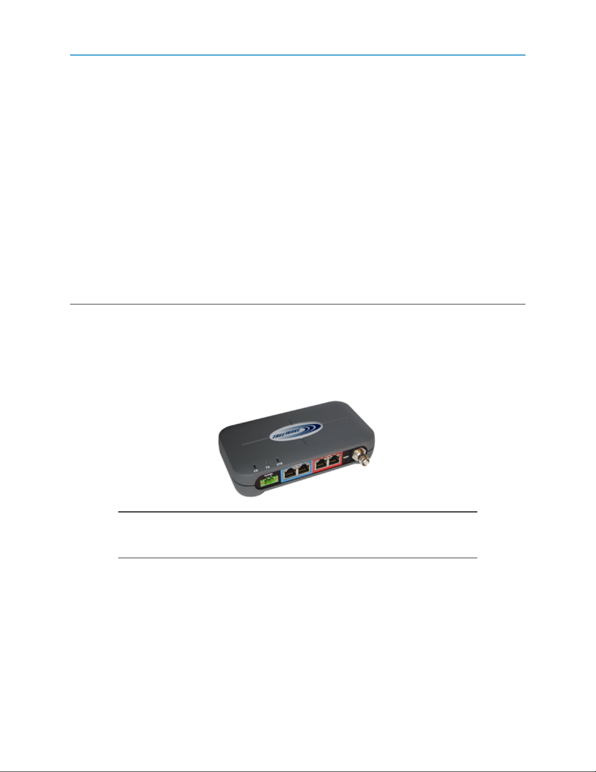
Getting to Know Your Plus-Style Transceiver
Your FGR2-PE transceiver has the following components:
l A power connector
l Two Ethernet ports, outlined in blue on the back of the transceiver
l Two Com ports, outlined in red on the back of the transceiver
l A diagnostic port
LUM0024AB Rev A
1
Page 18
FGR2-PE Wirelss Data Transceiver
This port is currently non-functioning. No settings and no diagnostics are delivered to this port. All
Plus-style transceivers must be programmed using Ethernet, either through the configuration Web
pages or using FreeWave Tool Suite. For more information about the setup tools available, see
"ConfigurationTool Options" on page 16.
l An antenna port
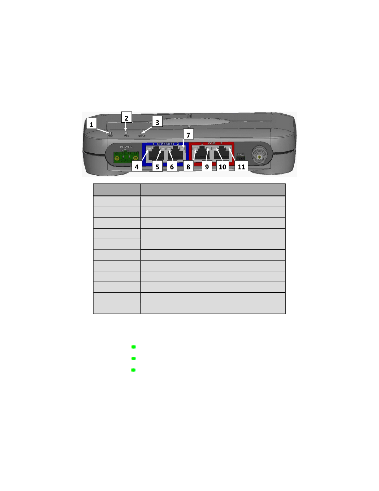
In addition, the transceiver includes LEDs to help you determine when data is being received or sent from the
transceiver, as well as to provide additional information about the transceiver's state.
Label # Above Description
1 CD
2 TX
3 CTS
4 Ethernet 1 10 BaseT Link/Activity
5 Ethernet 1 100 BaseT Link
6 Ethernet 2 10 BaseT Link/Activity
7 Ethernet 2 100 BaseT Link
8 COM 1 Data (C1)
9 Error 1 (E1)
10 COM 2 Data (C2)
11 Error 2 (E2)
Boot-Up LED Sequence
The LEDs on the Ethernet transceiver follow the sequence below when the transceiver powers up:
1.
C1 lights solid green
2.
C2 lights solid green , C1 remains lit
3.
E2 lights solid green , C1 and C2 remain lit
4. C1 turns off
5. C2 turns off
6. E2 turns off
Ethernet Port Conditions
LUM0024AB Rev A
2
Page 19
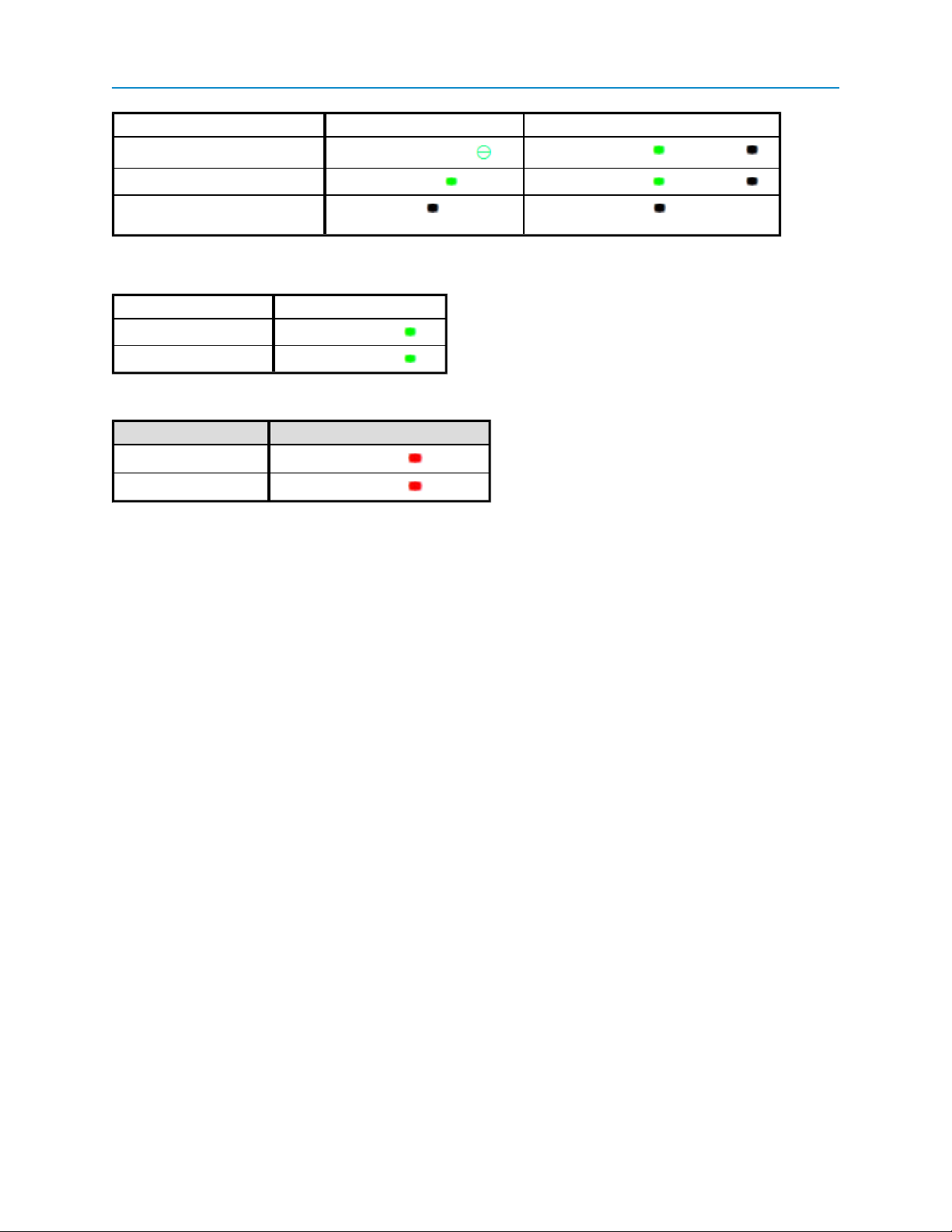
Status 10 BaseT Link/Activity 100 Baste T Link LED
Linked, data activity
User Manual and Reference Guide
Blinking/Flickering green Solid green (100 BaseT /Off (10 BaseT )
Linked, no data activity
Not linked. Checkthat cable is in
good condition and plugged in.
Solid green Solid green (100 BaseT /Off (10 BaseT )
Off Off
Error LED Conditions
Condition Error Light (E1/E2)
Buffer overflow locally
Buffer overflow in network
E1 LED is solid green
E2 LED is solid green
Com Port LED Conditions
Condition Communications Port 1 (C1) or 2 (C2)
Data streaming into RX
Data streaming out TX
Solid red bright
Solid red bright
Choosing a Location for the Transceivers
Placement of the FreeWave transceiver is likely to have a significant impact on its performance. The key to
the overall robustness of the radio link is the height of the antenna. In general, FreeWave units with a higher
antenna placement will have a better communication link. In practice, the transceiver should be placed away
from computers, telephones, answering machines, and other similar equipment. The 6-foot Ethernet cable
included with the transceiver usually provides ample distance for placement away from other equipment.
FreeWave offers directional and Omni directional antennas with cable lengths ranging from 3 to 200 feet.
When using an external antenna, placement of that antenna is critical to a solid data link. Other antennas in
close proximity are a potential source of interference. Use the Radio Statistics to help identify potential
problems.
An adjustment as little as 2 feet in antenna placement can resolve some noise problems. In extreme cases,
such as when interference is due to a Pager or Cellular Telephone tower, the band pass filters that FreeWave
offers may reduce this out-of-band noise.
Choosing Point-to-Point or Point-to-MultiPoint Operation
A Point-to-Point network is best suited when your network consists of one Gateway and one Endpoint
transceiver. You can add Repeaters to extend the reach of the network, but no other Gateway or Endpoint
may be added.
In a Point-to-MultiPoint network (also referred to as MultiPoint network) the transceiver, designated as a
Gateway, is able to simultaneously communicate with numerous Endpoints. In its simplest form, a MultiPoint
network functions with the Gateway broadcasting its messages to all Endpoints. If requested by the Master,
the Endpoints respond to the Gateway when given data by the device connected to the data port. This
response depends on your setup.
It is important to note the differences between Point-to-Point and MultiPoint networks. In a Point-to-Point
network all packets are acknowledged, whether sent from the Gateway to the Endpoint or from the Endpoint
LUM0024AB Rev A
3
Page 20
FGR2-PE Wirelss Data Transceiver
to the Gateway. In a MultiPoint network, you determine the set number of times outbound packets from the
Gateway or Repeater to Endpoints or other Repeaters are sent. The receiving transceiver, Endpoint or
Repeater, accepts the first packet received that passes the 32 bit CRC. However, the packet is not
acknowledged. On the return trip to the Gateway, all packets sent are acknowledged or retransmitted until
they are acknowledged. Therefore, the return link in a MultiPoint network is generally very robust.
Traditionally, a MultiPoint network is used in applications where data is collected from many instruments and
reported back to one central site. As such, the architecture of such a network is different from Point-to-Point
applications. The following parameters influence the number of transceivers that can exist in a MultiPoint
network:
1. Size of the blocks of data. The longer the data blocks, the fewer number of deployed Endpoints
can exist in the network.
2. Baud rate. The data rate between the transceiver and the device to which it is connected could
limit the amount of data and the number of transceivers that can exist in a network
3. The amount of contention between SlavesEndpoints. Polled Endpoints vs. timed
SlavesEndpoints.
4. Use of Repeaters. Using the Repeater setting in a MultiPoint network decreases overall network
capacity by 50%.
For example, if the network polls Endpoints once a day to retrieve sparse data, several hundred Endpoints
could be configured to a single Gateway. However, if each Endpoint transmits larger amounts of data or data
more frequently, then fewer Endpoints can link to the Gateway while receiving the same network
performance. When larger amounts of data are sent more frequently, the overall network bandwidth is closer
to capacity with fewer Endpoints.
For examples and additional information about data communication links, see the Examples of Data
Communication Links section later in this document.
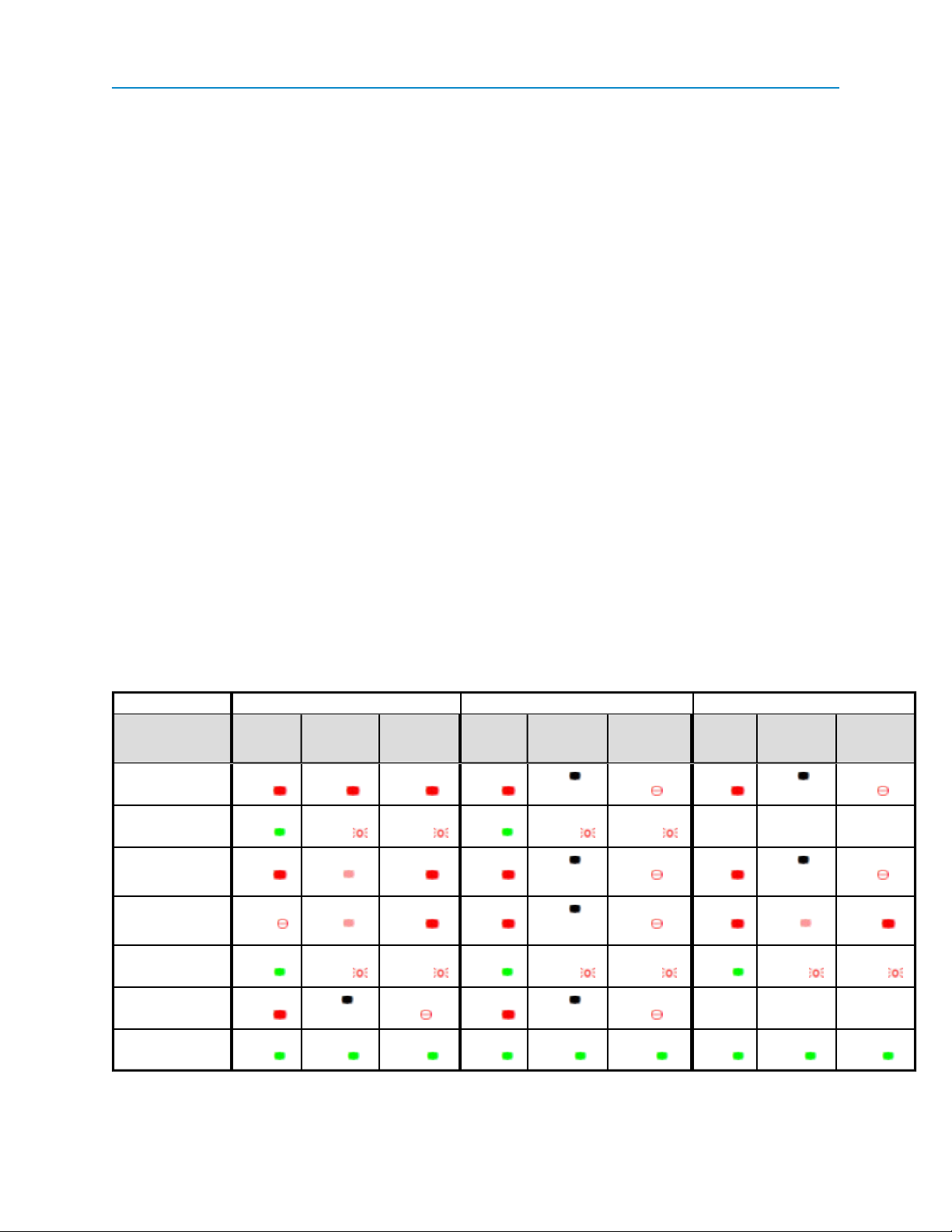
Point-to-Point Operation LEDs
Gateway Endpoint Repeater
Carrier
Condition
Powered, no link Solid red
Linked, noRepeater,
sending sparse data
Gateway calling Endpoint t hrough
Repeater
MasterGateway
linked to Repeater,
not to Endpoint
Repeater linked to
Endpoint
Mode 6 - waiting f or
ATD command
Setup Mode Solid
Detect
(CD)
bright
Solid
green
Solid red
bright
Flashing
orange
Solid
green
Solid red
bright
green
Transmit
(Tx)
Solid red
bright
Intermittent
flash red
Solid red
dim
Solid red
dim
Intermittent
flash red
Off Blinking
Solid
green
Clear t o
Send
(CTS)
Solid red
bright
Intermittent
flash red
Solid red
bright
Solid red
bright
Intermittent
flash red
red
Solid
green
Carrier
Detect
(CD)
Solid red
bright
Solid
green
Solid red
bright
Solid red
bright
Solid
green
Solid red
bright
Solid
green
Transmit
(Tx)
Off Blinking
Intermittent
flash red
Off Blinking
Off Blinking
Intermittent
flash red
Off Blinking
Solid
green
Intermittent
flash red
Intermittent
flash red
green
Clear t o
Send
(CTS)
red
red
red
red
Solid
Carrier
Detect
(CD)
Solid red
bright
n/a n/a n/a
Solid red
bright
Solid Red
bright
Solid
green
n/a n/a n/a
Solid
green
Transmit
(Tx)
Off Blinking
Off Blinking
Solid red
dim
Intermittent
flash red
Solid
green
bright
Intermittent
flash red
green
Clear t o
Send
(CTS)
red
red
Solid red
Solid
LUM0024AB Rev A
4
Page 21

Point-to-MultiPoint Operation LEDs
Carrier
Condition
Powered, not linked Solid red
Detect
(CD)
bright
User Manual and Reference Guide
Gateway Endpoint Repeater
Transmit
(Tx)
Solid red
dim
Clear t o
Send
(CTS)
Off Solid red
Carrier
Detect
bright
(CD)
Transmit
(Tx)
Off Blinking
Clear t o
Send
(CTS)
red
Carrier
Detect
(CD)
Solid red
bright
Transmit
(Tx)
Off Blinking
Clear t o
Send
(CTS)
red
Repeater and Endpoint
linked to Gateway, no
data
Repeater and Endpoint
linked to Gateway, Gateway sending data to Endpoint
Repeater and Endpoint
linked to Gateway, Endpoint s ending data to
Gateway
Gateway with diagnostics
program running
* in an idle condition, the CTS LED is solid red with a solid link, as the link weakens the CTS
LED on the Repeater and Endpoint begins to blink
Solid red
bright
Solid red
bright
Solid green
RCV data
or Solid red
bright
Solid red
bright
Solid red
dim
Solid red
dim
Solid red
dim
Solid red
dim
Off Solid
Off Solid
Intermittent
flash red
Intermittent
flash red
green
green
green
green
Solid
Solid
Off Solid red
Off Solid red
Intermittent
flash red
Intermittent
flash red
bright
bright
Solid red
bright
Solid red
bright
Solid
green
Solid
green
Solid
green
Solid
green
Solid red
dim
Solid red
dim
Solid red
bright
Solid red
bright
Solid red
bright
Solid red
bright
Solid red
bright
Solid red
bright
LUM0024AB Rev A
5
Page 22

LUM0024AB Rev A 6
Page 23

Chapter 2: Setting Up and
Programming Transceivers
This chapter provides details about setting up, programming, and defining who has access to your Plus-style
transceiver using the setup tools available. This chapter includes the following setup information:
l How to determine and set the IPaddresses of the transceiver you want to program.
You need the IPaddress of the transceiver before you can read the current settings or send new
settings to the transceiver.
l An introduction to the basic programming tools available to you and the parameters available within
each.
l How to define permissions using user accounts and group levels that grant access to the
transceiver and its settings.
l How to upgrade the firmware version running on the transceiver.
Basic Steps to Programming Plus-Style Transceivers
Use the following basic steps to program any FreeWavePlus-style transceiver.
1. Determine or set the transceiver's IPaddress.
2. Be familiar with your network and know if you have a Point-to-Point or Point-to-MultiPoint
configuration.
Most FreeWave networks are Point-to-MultiPoint.
3. Connect the transceiver to the configuration tool, such as Tool Suite or view the transceiver's
configuration Web pages.
LUM0024AB Rev A
7
Page 24

FGR2-PE Wirelss Data Transceiver
If using Tool Suite, ensure that the computer running Tool Suite has an IPaddress whose first
three octets are the same as the transceiver to which you are connecting.
4. Set the transceiver's operation mode, whether it is an Endpoint, Repeater, Gateway, and so on
and the network type it is in.
5. Program the transceiver, ensuring that all devices in a MultiPoint network have the same settings
for the following parameters:
l Frequency Key
l Max Packet Size
l Min Packet Size
l RFData Rate
l Network ID
6. Establish the Call Book settings if the transceiver is in a network not using Network IDs.
FreeWave recommends using Network IDs instead of the Call Book in MultiPoint networks. If a
large MultiPoint network is implemented using the Call Book with Slave Security enabled and the
Master radio is damaged, you are required to physically reprogram each Slave radio in the network,
which can be a time consuming process.
If you are using a Network ID, see "Network ID" on page 54
MultiPoint Network Considerations
When installing MultiPoint networks it is important to do some up front planning. Unlike Point-to-Point
networks, a Point-to-MultiPoint network requires several parameters are set consistently on all transceivers in
the network. This includes RF Data Rate, Min and Max Packet Size, Network ID, and the Frequency Key.
Note: If several independent MultiPoint networks are to be located in close proximity
the planning becomes more critical. In such cases, it becomes very important to
include as much frequency and time diversity as possible through use of
different Min and Max Packet Size. In some instances the use of the
MultiMaster Sync option may be required.
Powering the Transceiver
To provide power to the transceiver, connect it to a positive supply with +6 VDC to +30 VDC(typically, +12
VDC).
Using a dedicated power supply line is preferred. The power supply you use must provide more current than
the amount of current drain listed in the "FGR2-PE Specifications" on page 99 for the voltage you are using.
For example, if you are using +12 VDC, the power supply must provide above the drain that is required for
transmit using +12 VDC.
If the power supply line runs outside the radio enclosure, use electrostatic discharge (ESD) protectors to
protect the radio from electric shock, and transient voltage suppressors (TVS) to protect from an over-voltage
situation. Using both helps to ensure long-term, reliable operation. FreeWave does not supply these items,
however, they can be purchased at most electronic supply stores.
LUM0024AB Rev A
8
Page 25
User Manual and Reference Guide
Determining and Setting a Transceiver's IP Address
Before you can work with a Plus-style transceiver, you need to determine the transceiver's IP address. By
default, each Plus-style transceiver's IP address is 192.168.111.100 and its password is admin. If the
address has changed, if you do not know the transceiver's address, or you need to change the address, use
one of the following tools:
l HyperTerminal using the Com 1 serial port
l Discovery Server
Using HyperTerminal
To determine or set the IP address of a Plus-style transceiver, plug a serial cable into Com 1 (the left port),
with the transceiver disconnected from power. Then, follow the instructions below to open and setup
HyperTerminal and use the IPSetup menu.
To connect to the transceiver using HyperTerminal:
Note: The screen shots in the following sections represent HyperTerminal in Windows
XP. The display may vary slightly if you are using a different operating system.
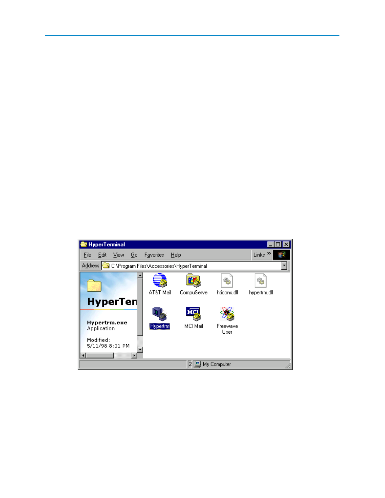
1. Click the Windows Start button and select Programs > Accessories > Communications, and
then select HyperTerminal.
A window similar to the following displays:
2. Double-click the Hypertrm.exe icon.
The following window displays:
LUM0024AB Rev A
9
Page 26
FGR2-PE Wirelss Data Transceiver
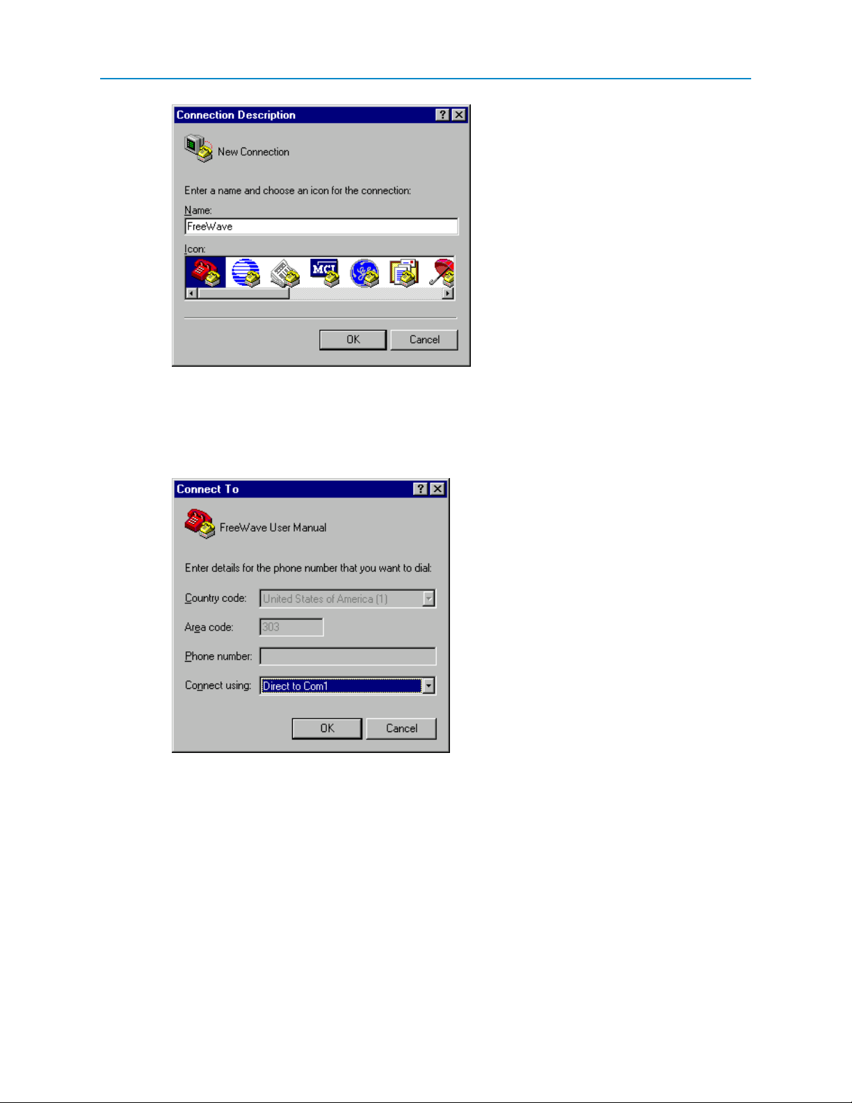
3. In the Name field, enter a descriptive name for the connection and select an icon from the Icon
selection box.
4. Click OK.
The Connect To dialog box displays.
5. In the Connect Using field, select the connection type to use.
Select the active Com Port to which the radio is connected. In most cases the connection type will
either Direct to Com1 or Direct to Com2.
6. Click OK.
The Properties dialog box displays for the selected connection type.
LUM0024AB Rev A
10
Page 27
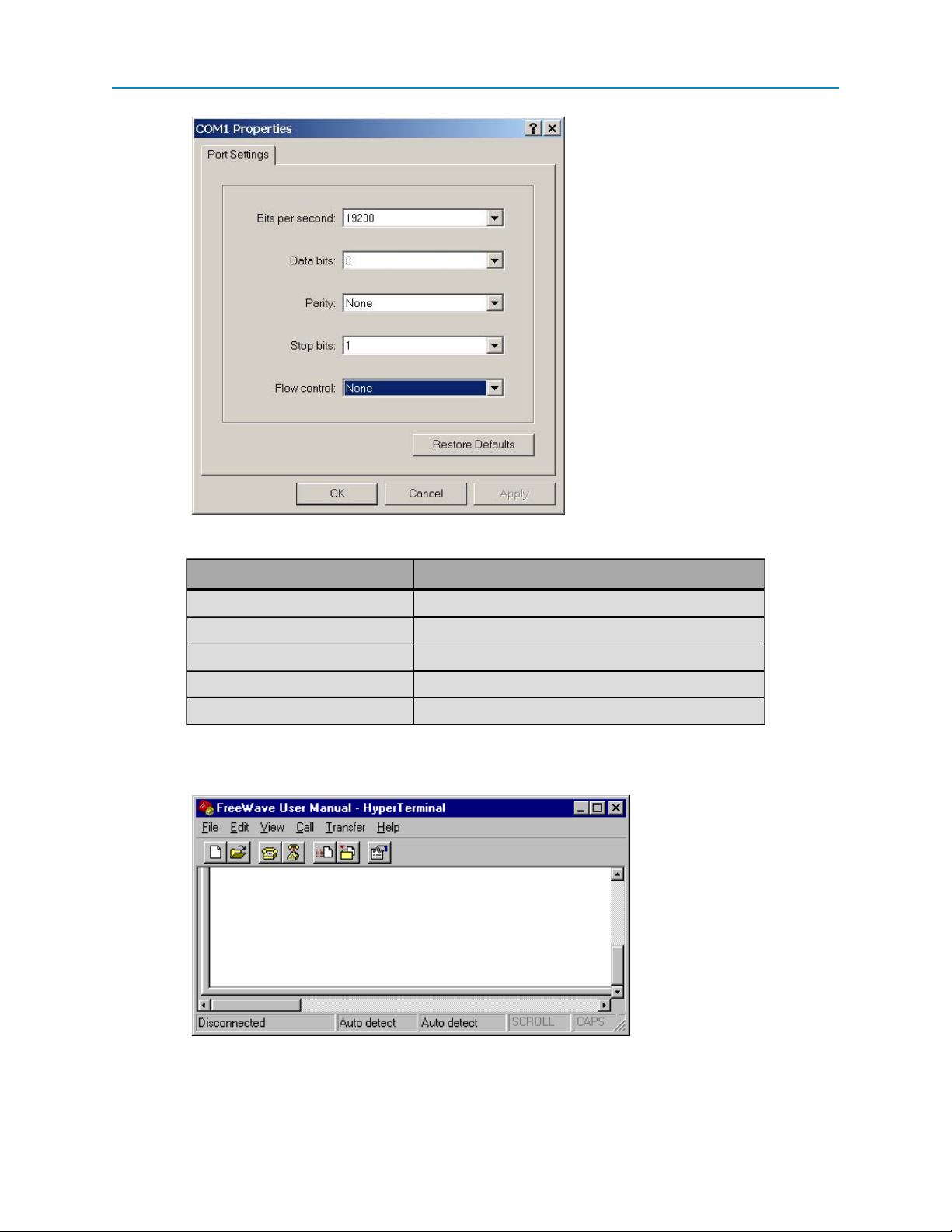
User Manual and Reference Guide
Enter the following port settings for a proper connection:
Port Setting Select
Bits per second 19200
Data bits 8
Parity None
Stop bits 1
Flow control None
7. After selecting the option for each setting, click OK.
The following HyperTerminal dialog box displays:
8. From the File menu, select Save to save the HyperTerminal connection settings
LUM0024AB Rev A
11
Page 28
FGR2-PE Wirelss Data Transceiver
Important: To make changes to the connection properties, you must first disconnect
the terminal session.
To set or determine the transceiver's IP address using HyperTerminal:
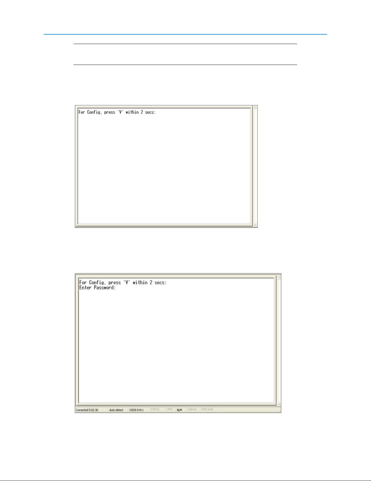
1. With the HyperTerminal session from the above procedure open, connect power to the transceiver.
After a few seconds, the following screen display in the HyperTerminal window:
2. Type a Y or a y within 5 seconds (even though the text says 2 seconds) to access the IP setup of
the transceiver.
Any other key exits, allowing the transceiver to complete the boot-up. After entering a Y, a
password prompt displays:
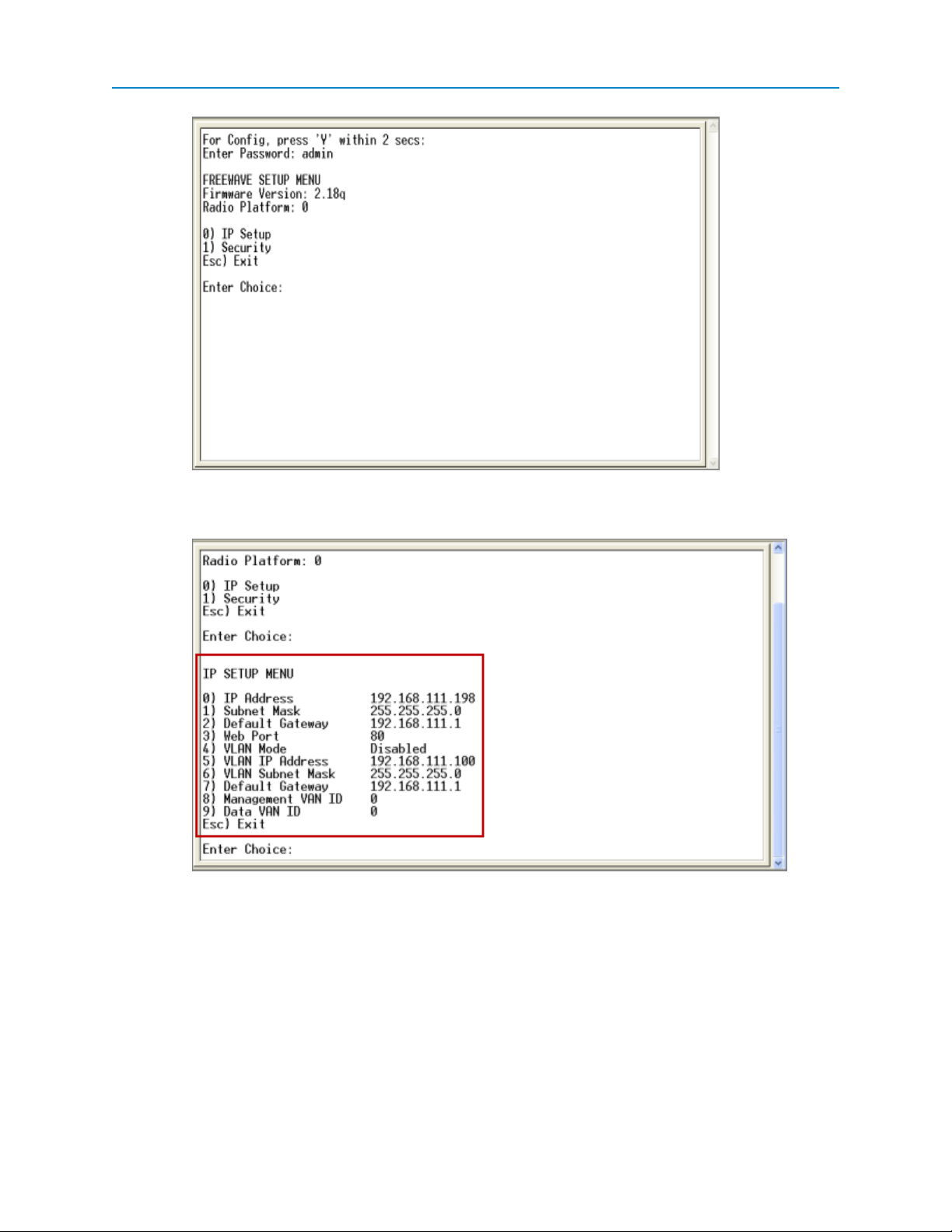
3. Enter the Administrator password (factory default password is admin) to display the Setup menu:
LUM0024AB Rev A
12
Page 29
User Manual and Reference Guide
4. Enter 0 to select the IP Setup Menu to display the IPAddress along with the other IP setup
options:
The transceiver's current IPaddress displays in the IP Address option.
5. To change the IP address or any other setting available here, select the number of the selection
and make the changes. Each setting is described in detail in the next chapter.
Selecting option 1 from the main Setup menu displays the Security menu: From this menu, some
of the security options can be changed. Option 0 clears the MAC Filter list, setting the transceiver
back to allowing all Ethernet traffic.
6. Exit the Setup menu to reboot the transceiver.
LUM0024AB Rev A
13
Page 30
FGR2-PE Wirelss Data Transceiver
Using Discovery Server
You can also determine and a set the IP address of a Plus-style transceiver with a firmware version of 2.8 or
higher using the FreeWave Discovery Server, a free utility available from FreeWave. Discovery Server is
available on the User Manual and System Tools CD and is also available for download from
www.freewave.com.
Note: Firewall software, such as Windows Firewall and McAfee Personal Firewall can
prevent the Discovery Server from operating properly. FreeWave recommends
disabling any Firewall software prior to running the Discovery Server.
This section provides instructions to determine and set the radio's IPaddress using Discovery Server. For
more information about the additional functionality available in the utility, see See "Using the Discovery
Server" on page 115
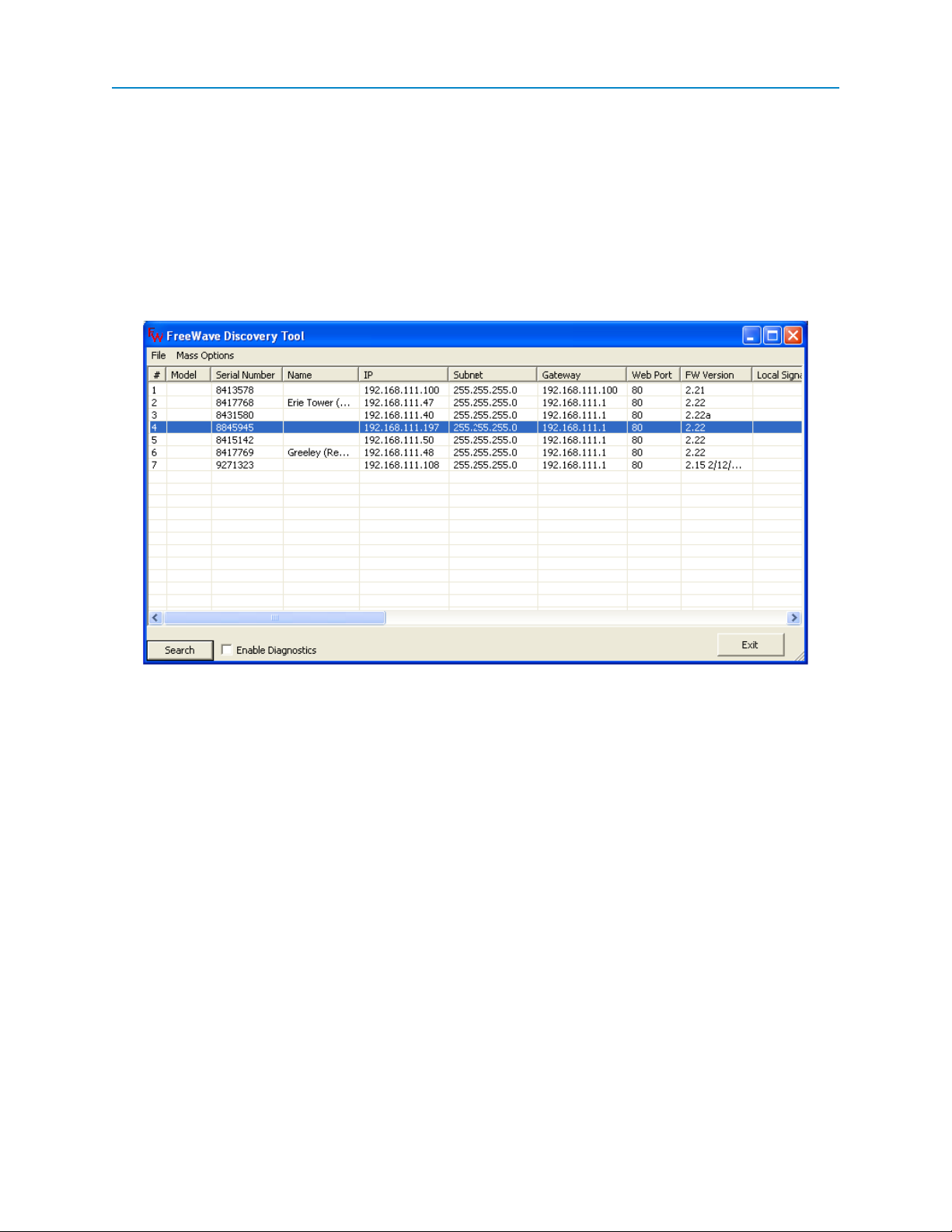
To determine a transceiver's IP address using Discovery Server:
1. Open Discovery Server.
When you open the Discovery Server application, it automatically attempts to discover any Plusstyle transceivers connected via Ethernet. The transceivers broadcast this information, so they
should be successfully discovered if they have a physical Ethernet connection to the network or
are able to communicate back through their Gateway.
Note: In firmware versions 2.13 and higher, Endpoints and Multipoint Repeaters can
only be discovered if the computer running Discovery Server is connected on
the Gateway side of the radio network. If connected to an Endpoint or MultiPoint
Repeater in this situation, only that radio and the Gateway are reported.
To set the transceiver's IPaddress using Discovery Server:
1. Open the Discovery Server application.
2. Right-click the discovered transceiver in the list that you want to change and select Change
Basic Settings.
LUM0024AB Rev A
14
Page 31

User Manual and Reference Guide
3. In the IP Address field, update the IPaddress to the address you want to assign to the
transceiver.
4. In the Password field, enter the current administrator password.
Transceivers running firmware version 2.14 or earlier only accept admin as the valid password.
Transceiver's running a later version of firmware accept any password up to 7 characters long.
Discovery Server can only change the basic settings of a transceiver if that transceiver’s
administrator password is seven characters long or less. Any passwords longer than seven
characters are not accepted in Discovery Server. You can use this password limitation to limit
which transceivers can be changed using the Discovery Server application.
5. Click Change to change the settings on the transceiver.
Resetting Transceivers to the Factory Default Settings
To reset a transceiver to the factory default settings, complete the following steps. For a list of factory
defaults, see "Factory Default Settings" on page 101.
1. Access HyperTerminal as described on page 9
2. With the HyperTerminal session open, connect power to the transceiver.
After a few seconds, the following screen display in the HyperTerminal window:
3. Type a Y or a y within 5 seconds (even though the text says 2 seconds) to access the IP setup of
the transceiver.
Any other key exits, allowing the transceiver to complete the boot-up. After entering a Y, a
password prompt displays:
LUM0024AB Rev A
15
Page 32

FGR2-PE Wirelss Data Transceiver
4. Enter default at the prompt and pressEnter.
The transceiver reboots, and all of the transceiver settings are reset to the factory defaults.
ConfigurationTool Options
After you have determined the Ethernet address of your Plus-style transceiver, you can use either Tool Suite
or the configuration Web pages accessed through any Web browser for general programming and setup.
Note: You can define a Plus-style transceiver's IP setup parameters, such as its
IPaddress, subnet mask, default gateway, and VLAN information using the
IPSetup menu in HyperTerminal or through Discovery Server. For information
about accessing the radio using HyperTerminal, see "Using HyperTerminal" on
page 9. For information about using the Discovery Server, see "Using the
Discovery Server" on page 115.
The parameters and statistics you can set and view for a Plus-style transceiver are grouped in the Web
interface in Pages and in Tool Suite in tabs. The tabs in Tool Suite mirror the configuration Web page menu
options.
LUM0024AB Rev A
16
Page 33

User Manual and Reference Guide
Each page or tab contains parameters that apply to the same area of functionality. For example, to setup a
serial port, you can access all the parameters for the first serial port in the Serial Setup 1 page.
Page Used To
Status View all device status information. For more information, see "Viewing
Transceiver Status and Statistics" on page 85.
IP Setup Setup the IP address, Subnet Mask, and Default Gateway of the radio.
Check with your Network Administrator before adjusting these settings.
Many of these settings are also available through Basic IP Setup in
HyperTerminal and the Discovery Server. For more information, see "IP
and Network Communication Settings" on page 31.
Serial Setup 1 and
Serial Setup 2
Set the port numbers and data settings for each serial port. These settings
need to match the device to which each port is connected. For more
information, see "Serial Port Settings" on page 39.
Radio Setup Set the transceiver’s Operation Mode, Transmission Characteristics,
Multipoint Parameters, and the Call Book. For more information, "Radio
Settings" on page 51.
Security Set the RADIUS server authentication, MAC filtering, and the AES
Encryption information. For more information, "Security Settings" on page
71.
SNMP Set the SNMP management features of the transceiver. The transceiver
supports SNMP versions 1, 2, and 3. All of the SNMP-manageable
objects for FreeWave's radios are contained in a single MIB file:
FREEWAVE-TECHNOLOGIES-MIB. This file is available from
FreeWave upon request. For more information, "SNMP Settings" on page
77.
LUM0024AB Rev A
17
Page 34

FGR2-PE Wirelss Data Transceiver
Page Used To
RMS Set FreeWave Redundant Master System units only. For details about
these settings, see the Redundant Master System User Manual Adden-
dum.
Diagnostics View the signal level, noise level, signal-to-noise delta, and receive rate for
each frequency available to the transceiver. For more information, see
"Viewing Transceiver Status and Statistics" on page 85.
Users Setup logins for the transceiver. Up to nine custom users can be created
for each transceiver, with the admin user being the permanent tenth user.
For more information, see "Creating User Logins" on page 22.
Tools Edit the site information and upgrade the transceiver’s Firmware. In a
MultiPoint Gateway, you can also enable the Global Change functionality.
The description and procedures in this manual are referenced as they appear in Tool Suite. If functionality is
available only through the configuration Web page, or is different than Tool Suite, the information is provided
as it displays in the Web pages, and indicates that you must use the Web page.
For more information about using Tool Suite, see the Tool Suite User Manual available on the User Manual
and System Tools CD or by selecting File > Help in the Tool Suite software. For more information about the
configurationWeb pages, see "Navigating the Web Pages" on page 19.
Reading Plus-Style Transceivers in Tool Suite
Prior to reading a transceiver's settings and programming a transceiver using Tool Suite, you need to know the
transceiver's IPaddress. For more information, see "Determining and Setting a Transceiver's IP Address" on
page 9.
In addition, the computer running Tool Suite must have an IPaddress within the same network. That is, the
first three octets of the IPaddress on the transceiver and the IPaddress on the computer running the Tool
Suite session must match.The last octet is unique. For information about changing a computer's IPaddress,
see "Changing the Computer IP Address in Windows" on page 121.
Note: For more information about using Tool Suite, see the Tool Suite User Manual
available on the User Manual and System Tools CD or by selecting File > Help
in the Tool Suite software.
1. Open Tool Suite and display the Configuration application.
2. Select or create an Ethernet network.
3. Enter the transceiver's IP address in the IPAddress field in the upper left corner of the Plus
Configuration ribbon.
4. Click Read Radio in the Plus Configuration ribbon.
5. Tool Suite attempts to connect to the transceiver and display it in the Discovered Devices tree.
6. Select the transceiver in the Discovered Devices tree to display its current settings in the setup
tabs.
LUM0024AB Rev A
18
Page 35

User Manual and Reference Guide
Accessing Configuration Web Pages
Each Plus-style transceiver has a built in Web interface that you can use to program its settings. To access
the Web interface, you must have a Web browser installed on your computer.
1. Plug the radio into either a computer or a switch/router using an RJ45 cable.
2. Open a Web browser such as Internet Explorer, Netscape, or Firefox and type the IP address of
the radio into the address bar.
For example, to access a radio with an IP address of 192.168.111.90, type http://192.168.111.100
into the address bar of the web browser.
A static IP address on the same subnet may need to be assigned to the router/switch and/or the
computer to access the transceiver. For more information, see "Changing the Computer IP
Address in Windows" on page 121. The default IP address from the factory is 192.168.111.100.
A prompt for a user name and password displays.
3. Enter the user name and password to access the transceiver.
The default user name for the administrator login is admin, the password is admin. The
administrator login has full permission to change all settings on the transceiver, including
upgrading firmware.
The default user name for the guest login is guest, the password is guest. The guest login can
view the settings. When logged in as a guest, you can see the Status, IP Setup, Serial Gateway
Setup, and Radio Setup pages. When logged in as a guest, you cannot save any changes, cannot
see the Security or Tools pages, and cannot reboot the transceiver.
Navigating the Web Pages
The configuration Web pages group the parameters into pages and provides the navigation features described
below.
The Pages menu displays on the left side of all pages. Click the items in this list to
navigate to the different configuration pages available for the transceiver. The currently
selected page is highlighted in teal.
Below the Pages List is the Reboot button. Click this button to force the transceiver to
reboot.
When making changes to the transceiver settings, click the Save/Apply button before
navigating away from a page or rebooting the transceiver to save your changes. No
changes take effect until you click Save/Apply.
When the changes have been successfully saved and applied,
the message Change Succeeded displays under the Reboot
button.
LUM0024AB Rev A
19
Page 36

FGR2-PE Wirelss Data Transceiver
Any change made in the configuration Web pages that is not yet
saved is highlighted in yellow. This highlight indicates that you
need to click Save/Apply before navigating away from the
page, or the changes will be lost.
Some setting changes (such as changes to the IP Setup) require a reboot to complete
the changes. When such a change is made, the Change Succeeded message below
the Reboot button changes to include a link labeled Reboot Required. Click either the
Reboot Required link or the Reboot button to reboot the transceiver and apply the
requested changes.The requested changes are not made until the transceiver is
rebooted. A Reboot Required link displays at the top of every page until the
transceiver is rebooted.
Providing Site Information
For each transceiver in your network, you can provide information to help identify that transceiver, such as a
name and contact information. The site information displays on the Status page in the configuration Web
pages.
To provide site information in Tool Suite:
1. Open Tool Suite and connect to the transceiver you want to set.
For more information, see "Reading Plus-Style Transceivers in Tool Suite" on page 18.
2. Ensure the Configuration application is displayed and clickRead Radio to read the transceiver's
current settings.
3. Click the Tools tab.
4. Provide any of the following information in the fields provided:
Field Description
Site Name Enter any text up to 25 characters that helps to identify the
transceiver.
Site Contact Enter any text up to 25 characters that provides information
about who to contact about the site's status.
System Name Enter any text up to 32 characters that helps to identify the
system in which the transceiver operates.
Notes Enter any additional text up to 50 characters about the
transceiver or the site.
5. Select a Tool Suite program option to send the changes to the transceiver. For more information
about using Tool Suite, see the Tool Suite User Manual available on the User Manual and System
Tools CD or by selecting File > Help in the Tool Suite software.
To provide site information in the configuration Web page:
1. Access the radio's configuration Web pages.
For more information, see "Accessing Configuration Web Pages" on page 19.
LUM0024AB Rev A
20
Page 37

User Manual and Reference Guide
2. In the Pages menu on the left side, click Tools to display the Tools page.
3. In the Change Site Information section of the page, provide any of the following information:
Field Description
Site Name Enter any text up to 25 characters that helps to identify the
transceiver.
Site Contact Enter any text up to 25 characters that provides information
about who to contact about the site's status.
System Name Enter any text up to 32 characters that helps to identify the
system in which the transceiver operates.
Notes Enter any additional text up to 50 characters about the
transceiver or the site.
4. Click Change Site Information to save your changes.
Using the MultiPoint Gateway to Change All Connected Transceivers
Note: The Global Change function can only be enabled or disabled using the
configuration Web pages.
Often, the settings on transceivers in your network should be the same as the settings in the MultiPoint
Gateway. Instead of changing each transceiver individually, you can use the Global Change function to push
the IPSetup, Radio Setup, Security, SNMP, and User settings to all connected transceivers in the network.
1. Access the Gateway's configuration Web pages. For more information, see "Accessing
Configuration Web Pages" on page 19.
2. In the Pages menu on the left side, click Tools to display the Tools page.
3. Click ENABLE Global Change Functionality in the middle of the page.
The button now displays DISABLE Global Change Functionality. Click that button to turn off
global changing.
When enabled, the following message displays at the top of every page for transceivers connected
to the Gateway.
On the pages that allow Global Changes, the Save/Apply button is replaced by the Push Locally button.
Any changes made to the parameters on that page are pushed to all the connected transceivers when you
click Push Globally.
Note: The settings on the MultiPoint Gateway are not changed during a Global
Change.
Note the following when the Global Change functionality is enabled:
l IP Setup page - The IP Address field becomes hidden, as it cannot be part of a Global Change.
l Radio Setup page - The Network Type and Modem Mode fields are hidden, as they do not
change as part of a Global Change.
LUM0024AB Rev A
21
Page 38

FGR2-PE Wirelss Data Transceiver
Important: Changes made to the settings on this page can cause the radios to lose
communication with the Gateway and/or MultiPoint Repeaters. Use caution when
making global changes.
l Security page - All settings on the Security page can be part of a Global Change.
Important: When changing the AES Encryption Key globally, first make the change
on the Multipoint Gateway. After the Gateway has been changed, you can push the
new key to the other transceivers in the network. If not done in this order, changing the
encryption key can cause transceivers to lose connectivity with the Gateway for an
extended period of time.
l SNMP page - All settings on the SNMP page can be part of a Global Change.
l Users page - The Edit Group Level Rights section and the User Accounts Level can be
adjusted using Global Changes; however, user accounts and user passwords cannot be created or
deleted using Global Changes.
Creating User Logins
To limit who can access the Plus-style transceivers in your network and who can edit configuration settings,
you can set up to nine custom user's with login access.
Note: The tenth login is the permanent admin login.
To create a login, do the following.
l Define your login group levels.
l Add users by creating user accounts and assign users to a group level.
l Set a user's password to login. When connecting to the transceiver through Tool Suite or through
the configuration Web pages, a password prompt displays.
Defining User Groups
User groups set the access rights for each Tool Suite tab or configuration Web page for a transceiver. Users
are assigned to a group, and then inherit the access rights that are set for that group.
You can create up to three groups (Groups 1, 2, and 3). Within each group, assign one of the following access
levels to each page or tab:
l No Access - Users cannot see the settings in the tab or page. Any attempt to navigate to the tab
or page displays an “Access Denied” message.
l Read Only - Users can see the settings in the tab or page, but cannot save or apply any changes.
l Full Access - Users are able to see the settings in the tab or page and can save and apply
changes.
When you create a user, you assign the user to a group. The group number corresponds to the user group and
the user inherits the permissions assigned to that group. For example, if Group 1 has Read Only access to
the IPSetup parameters and No Access to the Security parameters, any user assigned to Group 1 can view
IP Setup parameters but not make changes, and receives an Access Denied message if they try to access
the Security tab or page.
LUM0024AB Rev A
22
Page 39

Note: You cannot change the group assigned to the admin user. The admin user
always has Full Access to all pages.
To edit user group rights using Tool Suite:
1. Access the transceiver's settings in Tool Suite.
For more information, see "Reading Plus-Style Transceivers in Tool Suite" on page 18.
2. Click the Users tab to display the User settings.
3. For each level, select the access rights for each group of parameters.
For example, the Level 1 Account IP Setup field represents Group 1's access rights to the IP
Setup page or tab.
Your changes are saved automatically as you make them. However, be sure to apply them to the
transceiver.
To edit user group rights through the configuration Web pages:
1. Access the transceiver's Web page.
For more information, see "Accessing Configuration Web Pages" on page 19.
2. Click Users in the Pages menu to display the Users page.
User Manual and Reference Guide
3. In the Edit Group Level Rights section of the page, use the drop-down menus in each group to
select the access rights for each page.
4. Click Save/Apply to save your changes and apply them to the transceiver.
Adding and Deleting Users
Note: You can only create and edit users using the configurationWeb pages.
You can set up to nine custom users with login access to a Plus-style transceiver. The tenth login is the
permanent admin login.
To add a user:
1. Access the transceiver's Web page.
For more information, see "Accessing Configuration Web Pages" on page 19.
2. Click Users in the Pages menu to display the Users page.
3.
At the bottom of the User Accounts section of the page, click the green plus icon or click Add
User.
4. In the dialog box that displays, enter the following user information:
Field Description
User Name A name that identifies the user, for example guest or a
user's first initial and last name.
User Level Select 1, 2, or 3 to assign the user to a group.For more
Password and Confirm
Password
LUM0024AB Rev A
information, see "Defining User Groups" on page 22.
The user password to enter when accessing restricted
pages.
23
Page 40

FGR2-PE Wirelss Data Transceiver
5.
Click Add User to create the user account, or click the red icon in the upper right corner of the
dialog box to cancel without creating the user.
To delete a user:
1. Access the transceiver's Web page.
For more information, see "Accessing Configuration Web Pages" on page 19.
2. Click Users in the Pages menu to display the Users page.
3.
In the User Accounts section of the page, click the red icon next to the user that you want to
delete.
Changing User Passwords
Note: You can only change user's passwords in the configurationWeb page interface.
When you create a user, you assign that user a password. You can change the password for a user at
anytime.
1. Access the transceiver's configuration Web page.
For more information, see "Accessing Configuration Web Pages" on page 19.
2. Click Users in the Pages menu to display the Users page.
3.
Click the key icon.
4. In the first Confirm Password field, enter the new password and type it again in the second
Confirm Password field.
5.
Click Change Password to save the new password or click the red icon in the upper right
corner of the dialog box to cancel without changing the password.
Upgrading Plus-Style Transceiver Firmware Using TFTPServer
The Plus-style transceivers share a common firmware upgrade platform and process using the FreeWave
TFTP Server and a FreeWave-supplied firmware upgrade file. This section details the step-by-step process of
upgrading firmware either locally (directly connected to the transceiver via an Ethernet cable) or over-the-air
(OTA). Upgrading firmware locally is much faster than if done OTA.
Important: Only attempt an OTA firmware upgrade if the link is stable and of good
quality. If the link is unstable or poor, the firmware upgrade is likely to fail.
Upgrading firmware does not change any transceiver settings. The same is not true for downgrading firmware.
If you are considering downgrading your firmware version, contact FreeWave Technical Support for further
information.
LUM0024AB Rev A
24
Page 41

User Manual and Reference Guide
Warning! Downgrading an Plus-style transceiver from the current firmware version to
a previous firmware version may result in the transceiver settings becoming invalid.
FreeWave recommends resetting any downgraded transceiver to the factory defaults
using the steps provided in "Resetting Transceivers to the Factory Default Settings"
on page 15 before attempting to use or configure the transceiver.
The instructions in the following sections assume you know the IP address of the transceiver you want to
upgrade and that you are able to access the transceiver's configuration Web pages. If you are not able to do
this, contact FreeWave Technical Support for assistance.
Complete the following steps, described in detail below, to upgrade a Plus-style transceiver:
1. Configure the FreeWave TFTP Server.
2. Upgrade the firmware file using the Web configuration pages.
3. Verify the firmware upgrade.
Before You Get Started Upgrading Firmware Using the TFTPServer
Before you can upgrade a Plus-style transceiver's firmware, download the specific firmware file and install
FreeWave TFTP Server from www.freewave.com. If you are unsure which file you need or require
assistance, contact FreeWave Technical Support.
FreeWave recommends creating a folder on your computer desktop called Root and saving the firmware file
in that directory.
Configuring the TFTP Server
The FreeWave TFTP Server enables the transfer of the firmware file from your computer to the Plus-style
transceiver. After you download the FreeWave TFTP Server program, run the installer to gain access to the
executable program, fwTFTP.exe. After the installation, you are ready to configure the TFTP Server.
1. From the Windows Start menu, select All Programs > FreeWave Technologies >fwTFTP >
fwTFTP.exe.
If you installed the TFTP server in another location, follow that directory path and open the
fwTFTP.exe file.
2. After the application displays, click Configure to display the Server Configuration dialog box.
3. In the Root Folder field, click the icon next to the field and locate the folder in which you saved the
firmware upgrade file in "Before You Get Started Upgrading Firmware Using the TFTPServer" on
page 25.
LUM0024AB Rev A
25
Page 42

FGR2-PE Wirelss Data Transceiver
4. Click OK and verify that the folder is listed in the Root Folder field.
5. Click OK to return to the main TFTP Server window.
6. Click Start Server in the upper left of the TFTP Server window.
If the button and text are gray, the server is started.
7. Minimize (do not close) the FreeWave TFTP Server window and continue with "Upgrading
Firmware Using the Web Configuration Pages" on page 26.
Upgrading Firmware Using the Web Configuration Pages
After you have configured the FreeWave TFTPServer, you are ready to complete the firmware upgrade using
the transceiver's configuration Web pages.
1. Access the radio's configuration Web pages.
For more information, see "Accessing Configuration Web Pages" on page 19.
2. In the Pages menu on the left side, click Tools to display the Tools page.
3. In the Address of TFTP Server field in the TFTP Firmware Upgrade section of the page, the
IPaddress of the computer on which the TFTP Server is installed (not the transceivers's
IPaddress).
4. In the File Name field, enter the exact name of the firmware upgrade file you saved in the Root
directory on your desktop in "Before You Get Started Upgrading Firmware Using the TFTPServer"
on page 25.
If the file name includes an extension, such as .bin, include that in the name. For example, http2_
22.bin.
5. Click Upgrade Firmware.
The transceiver attempts to retrieve the firmware file from your computer. To verify that this is
working properly, or to see the status of the firmware retrieval, open the FreeWave TFTP Server
application that you minimized.
LUM0024AB Rev A
26
Page 43

User Manual and Reference Guide
If the firmware file is being uploaded to the transceiver, there is a new entry in the FreeWave TFTP
Server window, with a progress bar.
Over a local connection, for example connected directly from computer to transceiver using an
Ethernet cable, the upgrade can take less than 30 seconds. If the transceiver being upgraded is
not local, for example, an over-the-air firmware upgrade, the process can take significantly longer,
depending on the link quality.
On the Tools page in the configuration Web pages, the status of the firmware upgrade process
updates as the status changes.
After the firmware upgrade is complete, the transceiver reboots itself and returns to its
programmed state.
6. To verify the firmware upgrade, see "Verifying Firmware Upgrades" on page 28
Upgrading Plus-Style Firmware Globally
You can also upgrade firmware to all connected Plus-Style transceivers of the same type using the GLOBAL
Firmware Upgrade option. The Gateway sends a a copy of the firmware update in 1 KB sections to all
connected Endpoints and MultiPoint Repeaters. Each transceiver must successfully receive every section, or
it will not upgrade its firmware. Increasing the Broadcast Repeat setting increases the probability of
success, but slows down the overall process. The Gateway itself will not be upgraded during a Global
Upgrade.
Note: If the GLOBAL Firmware Upgrade button is selected on an Endpoint or a
Multipoint Repeater, that individual transceiver is not upgraded.It sends the
upgrade file to its Gateway, which will be upgraded. No other transceivers will
receive the file.
1. Access the radio's configuration Web pages.
For more information, see "Accessing Configuration Web Pages" on page 19.
LUM0024AB Rev A
27
Page 44

FGR2-PE Wirelss Data Transceiver
2. In the Pages menu on the left side, click Tools to display the Tools page.
3. In the Address of TFTP Server field in the TFTP Firmware Upgrade section of the page, enter the
IPaddress of the computer that is running the TFTP server (not the transceivers's IPaddress).
4. In the File Name field, enter the exact name of the firmware upgrade file you saved in the Root
directory on your desktop in "Before You Get Started Upgrading Firmware Using the TFTPServer"
on page 25.
If the file name includes an extension, such as .bin, include that in the name. For example, http2_
22.bin.
5. Click GLOBAL Firmware Upgrade.
Transceivers that successfully receive the firmware upgrade load the file to memory, and then
reboot. The reboot times are randomized within a short window, to keep every transceiver from
restarting at the same time.
6. To verify the firmware upgrade, see "Verifying Firmware Upgrades" on page 28
Verifying Firmware Upgrades
After the transceiver has taken a firmware upgrade and rebooted to its previously programmed state, you can
verify that the firmware upgrade was successful.
1. Refresh the transceivers's configuration Web pages by refreshing your browser window or opening
a new session.
If you are having problems viewing the Web pages, it may be necessary to clear your Web
browser cache and cookies. This process varies depending on the Web browser you are using. If
you need assistance, contact FreeWave Technical Support.
2. From the Pages menu on the left side, click Status to display the Status page.
This page should load by default when you log in.
The Firmware Version field in the Hardware Information section of the page displays the current
firmware version installed. Ensure this matches the firmware version to which you were upgrading.
You have completed the firmware upgrade process for your Plus-style transceiver!
Common Firmware Upgrade Issues and Solutions
”File Not Found” in either the configuration Web page or the FreeWave TFTP server
Check the filename of the firmware upgrade file. The file name must be typed exactly as the file is named. If
you have checked the name and are still unsuccessful, check the extension of the file. If your computer does
not display file name extensions, use the following instructions to enable file extensions (Windows XP, other
operating systems may vary):
1. Locate My Computer, either on your desktop or through the Start menu.
2. Select Tools from the top menu.
3. Select Folder Options.
4. Click the View tab.
LUM0024AB Rev A
28
Page 45

User Manual and Reference Guide
5. Scroll until you see Hide extensions for known file types and deselect the box next to this
option.
6. Click on Apply, and close the window.
Firmware upgrade times out
Ensure you are connecting to the proper IP address and that the transceiver is powered on. If you are able to
access the configuration Web pages, but the firmware upgrade times out, ensure the FreeWave TFTP Server
is configured properly and is started.
Firmware upgrading taking a long period of time
If the firmware upgrade is being done over-the-air, it can take a significant amount of time to complete the file
transfer. This time can be extended if the quality of the link is poor. FreeWave recommends only attempting
an over-the-air firmware upgrade with links that are stable and of high quality.
LUM0024AB Rev A
29
Page 46

LUM0024AB Rev A 30
Page 47

Chapter 3: IP and Network
Communication Settings
The parameters on the IP Setup tab or IP Setup configuration Web page are typically set by a network
administrator. These are the parameters that set the Ethernet address and other communications for the
transceiver. Within IPSetup, you set the following types of parameters:
l LAN interface configuration (management) - The local area network (LAN) settings.
l VLAN configuration (data) - The virtual local area network (VLAN)settings. A VLAN is a group of
devices with a common set of requirements that communicate as if they were attached to the
same domain, regardless of their network location.
Not every network needs or uses VLAN IDs. The VLAN Mode setting is normally set to Disabled.
Changes to VLAN settings should be approved by a network administrator.
l NTP client - The Network Time Protocol (NTP) settings. The device whose IPaddress you enter
here is the device that the transceivers in your network use to synchronize their internal clocks.
l Syslog server - The system logging settings. Enabling and setting IPaddresses in the system
server settings instructs the transceiver to send all its log entries to a system server. For more
information, see "Viewing the System Log" on page 71.
IP Parameter Reference
This section contains the following information as it applies to the IP setup parameters that you can set for the
transceivers described in this document.
parameter name (as you see it in Tool Suite)
Web Parameter: The name of the field as it appears in the configuration Web pages.
LUM0024AB Rev A
31
Page 48

FGR2-PE Wirelss Data Transceiver
Network Type: Point-to-Point, Point-to-MultiPoint, or Both
Default Setting: The factory default setting for the parameter.
Options: The options to which the parameter can be set.
Description: A description of what the parameter is and how it applies to the transceiver in
your network.
The parameters are listed in alphabetical order by their Tool Suite field name.
Default Gateway
Web Parameter: Default Gateway in the LANNetwork Interface Configuration section of the IP
Setup page.
Network Type: Both
Default Setting: 192.168.111.11
Options: Any valid IPaddress.
Description: The IPaddress of the Gateway's VLAN. This parameter is typically set by a
network administrator.
Note: Putting multiple devices on the network with the same IP address can
cause the entire network to crash.
IP Address
Web Parameter: IPAddress in the LANNetwork Interface Configuration section of the IP
Setup page.
Network Type: Both
Default Setting: 192.168.111.100
Options: Any valid IPaddress.
Description: The IPaddress assigned to the transceiver. Assign an unique IP address to
each transceiver in your network. The IP addresses must be in the proper
subnet.
It is also possible to have a transparent bridge with an IP address of
255.255.255.255, but serial port functionality, the Security features, and
access to the configuration Web pages is lost.
This field is hidden in the configuration Web page when Global Changes are
enabled. For more information about making global changes, see "Using the
MultiPoint Gateway to Change All Connected Transceivers" on page 21.
Note: Putting multiple devices on the network with the same IP address can cause the
whole network to crash.
When the VLAN Mode parameter is set to Tagged or Untagged, this IP information is assigned to the
Management portion of the transceiver (Setup pages, SNMP, Discovery Server). Any communication with the
transceiver's Setup pages, SNMP, or changes made using the Discovery Server need to be addressed to this
IP address and tagged with the Management VLAN ID.
LUM0024AB Rev A
32
Page 49

User Manual and Reference Guide
NTP Client Enable
Web Parameter Enable check box in the NTPClient section of the IP Setup page.
Network Type: Both
Default Setting: Disabled
Options: Disabled, Enabled
Description: Enables the Network Time Protocol (NTP) client on the transceiver. The
transceiver checks with the NTP Server specified in the NTP Client IP
Address parameter and sets its internal clock to the time and date specified
by the NTP server.
The transceiver only checks with the NTP server on its initial startup.
Note: Test the connectivity to the NTP server and its response to NTP
requests. If the transceiver is unsuccessful connecting to the NTP server
upon booting, it makes a new request to the server before every log file entry,
which can cause unnecessary network traffic.
NTP IP Address
Web Parameter IPAddress in the NTP Client section of the IPSetup page.
Network Type: Both
Default Setting: Blank
Options: Any valid IPaddress.
Description: The IP address of the NTP server. If the NTPClient is enabled, the
transceiver checks with this IPaddress upon startup to set its internal clock.
Push to Syslog Server
Web Parameter: Push to Server in the Syslog Server section of the IP Setup page.
Network Type: Both
Default Setting: Disabled
Options: Disabled, Enabled
Description: Enabling this option instructs the transceiver to send its log entries to the
system logging server identified in the Syslog Server 1 and Syslog Server 2
parameters.
Spanning Tree
Web Parameter Spanning Tree Enable check box in the LAN Network Interface
Configuration section of the IP Setup page.
LUM0024AB Rev A
33
Page 50

FGR2-PE Wirelss Data Transceiver
Network Type: Both
Default Setting: Disabled
Options: Disabled, Enabled
Description: Enabling this parameter causes a Gateway to use the Spanning Tree Protocol
(IEEE 802.1D). This protocol eliminates the possibility of the transceivers
creating a network loop, which can cause network-wide problems.
Spanning Tree Protocol does use transceiver bandwidth, as any Spanning
Tree transceivers are constantly communicating their network “location.”
FreeWave recommends leaving Spanning Tree disabled, unless the Spanning
Tree Protocol is required in your application.
Subnet Mask
Web Parameter: Subnet Mask in the LANNetwork Interface Configuration section of the
IPSetup page.
Network Type: Both
Default Setting: 255.255.255.0
Options: Any valid net mask address in your network.
Description: Used to route data in a sub-network. This parameter is typically set by a
network administrator.
Syslog Server 1
Web Parameter: Syslog Server 1 in the Syslog Server section of the IPSetup page.
Network Type: Both
Default Setting: 0.0.0.0
Options: Any valid IPaddress.
Description: The IP address of a system log server. If Push To Server is enabled, the
transceiver sends all log entries to the IP address entered in this parameter.
Syslog Server 2
Web Parameter: Syslog Sever 2 in the Syslog section of the IP Setup page.
Network Type: Both
Default Setting: 0.0.0.0
Options: Any valid IPaddress.
Description: The IP address of a second system log server. If system logging is enabled,
the transceiver sends all log entries to the IP address entered in this field. The
transceiver sends logs to both server entries, Syslog Server 1 and Syslog
Server 2, concurrently. If a second server does not exist, enter 0.0.0.0.
LUM0024AB Rev A
34
Page 51

User Manual and Reference Guide
VLAN Data ID
Web Page: Data VLAN ID in the VLAN Configuration (Data) section of the IP Setup page.
Network Type: Both
Default Setting: 0
Options: Any valid VLAN ID between 1 and 4095.
Description: Data using this VLAN ID is allowed to come into or be sent out of the
transceiver’s local Ethernet port and is allowed to access the serial ports via
the terminal server.
VLAN Default Gateway
Web Parameter Default Gate in the VLANConfiguration (Data) section of the IPSetup page.
Network Type: Both
Default Setting: Blank
Options: Any valid IPaddress.
Description: The IP address for the appropriate default Gateway for the Data VLAN IP
address.
VLAN IP Address
Web Parameter: IP Address field in the VLANConfiguration (Data) section of the IP Setup
page.
Network Type: Both
Default Setting: Blank
Options: Any valid IP Address.
Description: When the VLAN Mode is set to Tagged or Untagged, the IP address entered
in this parameter is assigned to the Data portion of the transceiver (Ethernet
port traffic and terminal server communication).
Any data destined for one of the transceiver's serial ports or its Ethernet port
needs to be addressed to this IP address and tagged with the Data VLAN ID.
.
VLAN Management ID
Web Parameter: Management VLAN ID in the VLANConfiguration (Data) section of the IP
Setup page.
Network Type: Both
Default Setting: 0
LUM0024AB Rev A
35
Page 52

FGR2-PE Wirelss Data Transceiver
Options: Any valid VLAN ID between 1 and 4095.
Description: Computers and devices using the VLAN ID entered here are able to access
the transceiver’s Setup pages, receive SNMP information, send SNMP
commands, and view the transceiver in the FreeWave Discovery Server.
VLAN Mode
Web Parameter: Mode in the VLAN Configuration (Data) section of the IP Setup page.
Network Type: Both
Default Setting: Disabled
Options: l Disabled - VLAN will not be used.
l Tagged - If the data coming into the transceiver’s local Ethernet port is
tagged with a VLAN ID, select this option. The transceiver bridges the data,
leaving the VLAN ID as-is.
l Untagged - If the data coming into the transceiver's local Ethernet port is
not tagged with a VLAN ID, select this option. The transceiver accepts the
data, tags it with the VLAN ID entered in the Data VLAN ID field, and
sends it across the radio link. Data arriving at this transceiver and being
sent out of the local Ethernet port has any VLAN tag removed before being
sent out of the port
Description: Determines whether VLAN is active and in which mode it is used.
Note: Not every network needs or uses VLAN IDs. The Mode setting is
normally kept at Disabled. Your network administrator should approve any
changes.
VLAN Subnet Mask
Web Parameter: Subnet Mask in the VLAN Configuration (Data) section of the IP Setup page.
Network Type: Both
Default Setting: Blank
Options: Any IPV4 net mask address.
Description: The subnet mask for the Data VLAN IP address, for example 255.255.255.0.
Web Page Port (http)
Web Parameter: Web Page Port on the IP Setup page.
Network Type: Both
Default Setting: 80
Options: Any valid TCP port from 1 to 65535.
LUM0024AB Rev A
36
Page 53

User Manual and Reference Guide
Description: Use this setting to change the assigned port for the configuration Web pages.
The default setting is port 80, the standard Web page port. If this setting is
changed from port 80, the proper port number must be included when
accessing the Setup pages.
For example, http://<IP address>:<Port>, where <IP address> is the IP
address of the transceiver, and <Port> is the port number assigned in this
parameter.
If an invalid TCP port is entered, the radio defaults the Web Page Port setting
to 80.
:
LUM0024AB Rev A
37
Page 54

LUM0024AB Rev A 38
Page 55

Chapter 4: Serial Port Settings
Use the settings on the Serial Setup tab or page to set the serial ports on the transceiver. The ports are labeled
1 and 2 on the physical transceiver. See the transceiver illustration in "Getting to Know Your Plus-Style
Transceiver" on page 1. Within Serial Setup, you can set the following parameter types:
l Terminal Server Configuration - The first setting you need to set for either serial port is whether
the port acts as a TCPterminal server, TCP client, UDP client, or Multicast.
l Serial Settings - The data transmission settings such as the Baud Rate and Flow Control. Set
these parameters to match the device to which the port is connected.
Each serial port is setup independently and configured on its own tab or Web page. The ports can have
different baud rates, parity, protocol, and so on, but must match the device to which they are connected. To
access either port, a client needs to call the IPaddress of the transceiver plus its assigned port number.
Note: You can also view the status of each serial port. For more information, see
"Viewing a Serial Port's Status" on page 41.
Setting a Serial Port's Mode
The first parameter you need to set for either serial port is whether the port acts as a TCPterminal server,
TCP client, UDP client, or Multicast.
To set a serial port's Mode inTool Suite:
1. Open Tool Suite and connect to the transceiver you want to set.
For more information, see "Reading Plus-Style Transceivers in Tool Suite" on page 18.
2. Ensure the Configuration application is displayed and clickRead Radio to read the transceiver's
current settings.
3. Click the serial port tab for the port you want to set up.
LUM0024AB Rev A
39
Page 56

FGR2-PE Wirelss Data Transceiver
4. Select Enabled in one of the following fields to enable that mode. If all the fields are set to
Disabled, then the port is disabled.
l TCP Server Enable - Sets the port as a TCP terminal server.
l TCPClient Enable - Sets the port as a TCP client to the IPaddress and port entered in the
TCP Client IP and TCP Client Port fields.
l UDP/Multicast Enable - Enables the transceiver as a UDP terminal server using the port
number entered in the UDP Local Port parameter or as a one-to-many connection from the
MultiPoint Gateway’s serial port to the interested MultiPoint Repeaters’ and/or Endpoints’
serial ports if the Use as Multicast parameter is also enabled.
5. Select a Tool Suite program option to send the changes to the transceiver. For more information
about using Tool Suite, see the Tool Suite User Manual available on the User Manual and System
Tools CD or by selecting File > Help in the Tool Suite software.
To set a serial port's Mode in the configuration Web pages:
1. Access the radio's configuration Web pages. For more information, see "Accessing Configuration
Web Pages" on page 19.
2. In the Pages menu on the left side, click the serial port you want to configure to display that Serial
Port's page.
3. In the Mode field, select from the following options:
l Disabled - Disables the port. This is the default setting.
l TCP Server Enable - Sets the port as a TCP terminal server.
l TCPClient Enable - Sets the port as a TCP client to the IPaddress and port entered in the
TCP Client IP and TCP Client Port fields.
l UDP - Enables the transceiver as a UDP terminal server using the port number entered in the
UDP Local Port parameter.
l Multicast - Allows a one-to-many connection from the MultiPoint Gateway’s serial port to the
interested MultiPoint Repeaters’ and/or Endpoints’ serial ports.
4. Click Save/Apply to save the changes before moving away from the page.
Disabling Serial Ports
If a serial port on the transceiver is not used, you can disable it. If both ports are disabled, the Basic IPSetup
for the transceiver still works through Port 1.
To disable a serial port in Tool Suite:
1. Open Tool Suite and connect to the transceiver you want to set.
2. Ensure the Configuration application is displayed and clickRead Radio to read the transceiver's
current settings.
3. Click the serial port tab for the port you want to set up.
4. Ensure the following fields are set to Disabled:
LUM0024AB Rev A
40
Page 57

l TCP Server Enable
l TCP Client Enable
l UDP/Multicast Enable
5. Select a Tool Suite program option to send the changes to the transceiver. For more information
about using Tool Suite, see the Tool Suite User Manual available on the User Manual and System
Tools CD or by selecting File > Help in the Tool Suite software.
To disable a serial port in the configuration Web pages:
1. Access the radio's configuration Web pages. For more information, see "Accessing Configuration
Web Pages" on page 19.
2. In the Pages menu on the left side, click the serial port you want to configure to display that serial
port's page.
3. In the Mode field, select Disabled.
4. Click Save/Apply to save the changes before moving away from the page.
Using the Serial Port as an Alarm Client
User Manual and Reference Guide
If you select to use either serial port as a TCPServer, you can also enable that port to be an alarm client. To
enable the port as an alarm client, set the Utilize as Alarm field to Enabled (select Enable Alarm Client
check box on the Serial Setup configuration Web page). In addition, you also need to set the following
parameters to determine what constitutes and alarm and the action the transceiver takes when in an alarm
state.
l Alarm IP &Port - Described on next page.
l Drop Link - Described on page 43
l Alarm Retry Limits (Attempts) - Described on page 43.
l TCP Server Inactivity Timeout - Described on page 47.
Viewing a Serial Port's Status
Note: You can view a serial port's status only through the Web Configuration pages.
For each serial port on the transceiver you can view status information.
1. Access the radio's configuration Web pages.
For more information, see "Accessing Configuration Web Pages" on page 19.
2. In the Pages menu on the left side, click either Serial Setup 1 or Serial Setup 2, depending on the
port for which you want to view status information.
3. Click Serial Port Status at the bottom of the page to display the Serial Port Status window.
This page updates every 5 seconds. Click Refresh at the bottom of the page to manually refresh
the page.
The following status information is available for each serial port.
LUM0024AB Rev A
41
Page 58

FGR2-PE Wirelss Data Transceiver
Ethernet (Rx and Tx)
The amount of data received (rx) and transmitted (tx) from the terminal server to the port. Received data
indicates data received on the transceiver from the serial port. Transmitted data indicates data sent from the
transceiver out the serial port. This amount is listed in bytes.
Serial (Rx and Tx)
The amount of data received (rx) and transmitted (tx) from the serial port. Received data indicates data
coming from the connected device into the serial port. Transmitted data indicates data sent out the serial port
to the connected device. This amount is listed in bytes.
Status
The current status of the Terminal Server. For example, Waiting, Connected, and so on.
Serial Port Parameter Reference
This section contains the following information as it applies to the serial port parameters that you can set for
the transceivers described in this manual.
parameter name (as you see it in Tool Suite)
Web Parameter: The name of the field as it appears in the configuration Web pages.
Network Type: Point-to-Point, Point-to-MultiPoint, or Both
Default Setting: The factory default setting for the parameter.
Options: The options to which the parameter can be set.
Description: A description of what the parameter is and how it applies to the transceiver in
your network.
The parameters are listed in alphabetical order by their Tool Suite field name.
Alarm IP & Port
Note: Available only in the Serial Setup configuration Web page.
Web Parameter: Alarm IP& Port in the TCP Server Settings section of the Serial Setup page.
Network Type: Both
Default Setting: Blank
Options: Any valid IPaddress and any valid port number between 0 and 65535.
Description: The IP address and TCP port number the transceiver connects to when it
becomes a client per the Utilize as Alarm setting. Enter the IP address in the
field to the left of the colon. Enter the TCP port number to the right of the colon.
For more information about setting up alarm clients, see "Using the Serial Port
as an Alarm Client" on page 41.
LUM0024AB Rev A
42
Page 59

User Manual and Reference Guide
Alarm Retry Limit (Attempts)
Web Parameter: Alarm Retry Limit in the TCP Server Settings of the Serial Setup page.
Network Type: Both
Default Setting: 0
Options: Any number of retry attempts.There is no limit.
Description: The number of times the transceiver attempts to create an outgoing TCP
connection when acting as an alarm client (when the Utilize For Alarm
parameter is set to Enabled).
When the transceiver reaches the number of retries listed in this setting
without a successful connection, it stops trying and acts as if no alarm was
received. The incoming data is flushed from the transceiver’s data buffer. If
new incoming data is received, the transceiver attempts to connect again. A
setting of 0 means that the transceiver continuously tries to connect to the
alarm server until the transceiver is rebooted.
For more information about setting up alarm clients, see "Using the Serial Port
as an Alarm Client" on page 41.
Drop Link
Web Parameter: Maintain/Drop Link in the TCP Server Settings section of the SerialSetup
page.
Network Type: Both
Default Setting: Disabled
Options: Disabled, Enabled
Description: Enabling Drop Link causes the outgoing connection to the address set in the
Alarm IP & Port field to drop as soon as the serial data is sent. Disabling
Drop Link keeps the connection to the remote IP address and port number
active until the transceiver is rebooted or the server side drops the link.
For more information about setting up alarm clients, see "Using the Serial Port
as an Alarm Client" on page 41.
Multicast IP
Web Parameter: Multicast Address & Port in the Multicast Settings section of the Serial
Setup page.
Network Type: Both
Default Setting: 0.0.0.0
Options: Any valid multicast address from 224.0.0.0 to 239.255.255.255.
Description: The IP address used for Multicast if the serial port is set to Multicast mode. In
a MultiPoint Gateway, this is the sending address. In MultiPoint Endpoints and
MultiPoint Repeaters, this is the address they register interest in.
LUM0024AB Rev A
43
Page 60

FGR2-PE Wirelss Data Transceiver
In the configuration Web pages, enter the IP address in the field to the left of
the colon. Enter the port number in the field to the right of the colon.
Multicast Port
Web Parameter: Multicast Address & Port in the Multicast Settings section of the Serial
Setup page.
Network Type: Both
Default Setting: Blank
Options: Any valid port number between 0 and 65535.
Description: The port used if the serial port is set to Multicast mode.
In the configuration Web pages, enter the IP address in the field to the left of
the colon. Enter the port number in the field to the right of the colon.
Serial Baud Rate
Web Parameter Baud Rate in the Serial Setting section of the Serial Setup page.
Network Type: Both
Default Setting: 19200
Options: 300, 600, 1200, 2400, 4800, 9600, 19200, 38400, 57600, 115200
Description: The actual baud rate for the transceiver’s data port. This setting is the
communication rate between the transceiver and the instrument to which it is
connected, and is independent of the baud rate for the other transceivers in the
network. It is also independent of the other serial port on the transceiver. Set
the baud rate to the highest level supported by the device to which it is
connected. With a poor radio link, however, this may actually result in slower
data communications. For example, a pair of transceivers may be used in an
application to send data from remote process instrumentation to the engineer's
computer. In this application, the baud rate for the transceiver on the
instrumentation might be set to 9600, and the transceiver on the engineer's
computer might be set to 57,600.
Serial CD Mode
Web Parameter: CD Mode in the Serial Settings section of the Serial Setup page
Network Type: Both
Default Setting: Normal
Options: l Normal - CD is asserted when a TCP connection to the associated port is
made, and de-asserted when the TCP connection is closed. Most serial
devices use this option.
l Keyed - CD asserts 500 µs before transmit, and de-asserts 1 ms after the
transmission of the first bit of the last byte of data. This option should be
used with serial devices that require the CD line to be asserted prior to the
LUM0024AB Rev A
44
Page 61

User Manual and Reference Guide
transmission of data.
Description: Controls the function of the CD line on the serial port.
Serial Data Bits
Web Parameter: Data Bits in the Serial Settings section of the Serial Support page.
Network Type: Both
Default Setting: 8
Options: 5, 6, 7, 8
Description: The number of data bits the serial port sends. This setting should match the
number of data bits the connected device requires or is set to.
Serial Flow Control
Web Parameter: Flow Control in the Serial Settings section of the Serial Setup page.
Network Type: Both
Default Setting: None
Options: l None - Uses software flow control (XON / XOFF).
l Hardware - Uses hardware flow control (RTS / CTS).
Description: Indicates whether hardware flow control is used on the serial port.
Serial Interface
Web Page: Interface in the Serial Settings section of the Serial Setup page.
Network Type: Both
Default Setting: RS232
Options: RS232, RS485, RS422
Description: The serial protocol the serial port uses. This protocol should match the
protocol the connected device requires. For pinout information, see "RS422
and RS485 Full Duplex Pinouts" on page 96.
Serial Modbus RTU
Web Parameter Modbus RTU in the Serial Settings section of the Serial Setup page.
Network Type: Both
Default Setting: Enabled
Options: Disabled, Enabled
Description: Adjusts for Modbus RTU timing. When enabled, the transceiver gathers data
on the serial port until there is a break in the data due to Modbus RTU timing
(every 256 bytes). The data is then sent as one TCP packet.
LUM0024AB Rev A
45
Page 62

FGR2-PE Wirelss Data Transceiver
Setting this option is recommended for any serial data that consist of many
small packets of data.
Serial Parity
Web Parameter: Parity in the Serial Settings section of the Serial Setup page.
Network Type: Both
Default Setting: None
Options: None, Even, Odd
Description: The parity type the serial port uses. This type should match the parity the
connected device requires.
Stop Bits
Web Page: Stop Bits in the Serial Settings section of the Serial Setup page
Network Type: Both
Default Setting: 1
Options: 1, 2
Description: The number of stop bits the serial port sends. This number should match the
number of stop bits the connected device requires.
TCP Client Enable
Web Parameter: Mode in the Terminal Server Configuration section of the Serial Setup page.
Network Type: Both
Default Setting: Disabled
Options: Disabled, Enabled
Description: Enabling this parameter sets the operating mode of the transceiver's terminal
server to TCP Client. Your selection determines which other parameters are
available for the serial port. Upon booting up, the radio creates a persistent
outgoing TCP connection to the TCPClient IPand TCP Client Port. Any
data sent to the associated serial port on the transceiver is automatically
directed to the entered IP address and port number.
LUM0024AB Rev A
46
Page 63

User Manual and Reference Guide
TCP Client IP
Web Parameter IPAddress & Port in the TCPClient Settings section of the Serial Setup
page.
Network Type: Both
Default Setting: 0.0.0.0
Options: Any valid IP address.
Description: The IP address the transceiver creates a connection to on boot-up, when the
transceiver is set to TCP Client mode. In the configuration Web page, enter
the IP address to the left of the colon and the TCP port number in the box to
the right of the colon.
TCP Client Port
Web Parameter IPAddress & Port in the TCPClient Settings section of the Serial Setup
page.
Network Type: Both
Default Setting: 0000
Options: Any valid port number between 0 and 65335.
Description: The port number the transceiver creates a connection to on boot-up, when the
transceiver is set to TCP Client mode. In the configuration Web page, enter
the IP address to the left of the colon and the TCP port number in the box to
the right of the colon.
TCP Server Enable
Web Parameter: Mode in the Terminal Server Configuration section of the Serial Setup page.
Network Type: Both
Default Setting: Disabled
Options: Disabled, Enabled
Description: Enabling this parameter sets the operating mode of the transceiver's terminal
server to TCP Server. Your selection determines which other parameters are
available for the serial port.
TCPServer Inactivity Timeout
Web Parameter: Inactivity Timeout in the TCPServer Settings of the SerialSetup page.
Network Type: Both
Default Setting: 10
LUM0024AB Rev A
47
Page 64

FGR2-PE Wirelss Data Transceiver
Options: Any number of seconds.
Description: Controls how long, in seconds, an incoming TCP connection must be idle (that
is, no data being transferred) before the transceiver drops the connection.
A setting of 0 means that the transceiver never disconnects an idle
connection—all disconnects need to come from the client.
Note: In some RTUs, after the RTU is connected to the transceiver as a
client, the RTU does not properly disconnect the TCP session. To help
overcome this potential behavior of some RTUs, FreeWave recommends
setting Inactivity Timeout to 10.
TCPServer Port
Web Parameter: Port in the TCP Server Settings section of the Serial Setup page.
Network Type: Both
Default Setting: Blank
Options: Any valid TCP port between 0 and 65535.
Description: The TCP port the transceiver listens to for incoming TCP connections.
UDP Local IP Port
Web Parameter: Local IP Port in the UDPSettings section of the Serial Setup page.
Network Type: Both
Default Setting: 0000
Options: Any valid IP port number between 0 and 65535.
Description: The UDP port the transceiver listens to for connections when the
UDP/Multicast parameter is set to Enabled.
UDP Power Up IP
Web Parameter Power UP Dest. IP & Port in the UDPSettings section of the SerialSetup
page.
Network Type: Both
Default Setting: 0.0.0.0
Options: Any valid multicast address from 224.0.0.0 to 239.255.255.255.
Description: When the serial port is set to UDP mode, enter the IPaddress where the
transceiver sends any serial data coming into its serial port.
In the configuration Web pages, enter the IP address in the field to the left of
the colon. Enter the port number in the field to the right of the colon.
LUM0024AB Rev A
48
Page 65

User Manual and Reference Guide
UDP Power Up Port
Web Parameter Power UP Dest. IP & Port in the UDPSettings section of the SerialSetup
page.
Network Type: Both
Default Setting: 0000
Options: Any valid port number between 0 and 65535.
Description: The port used if the serial port is set to UDP mode.
In the configuration Web pages, enter the IP address in the field to the left of
the colon. Enter the port number in the field to the right of the colon.
UDP/Multicast Enable
Web Parameter: Mode in the Terminal Server Configuration section of the Serial Setup page.
Network Type: Both
Default Setting: Disabled
Options: Disabled, Enabled
Description: Enables the transceiver as a UDP terminal server using the port number entered in the
UDP Local Port parameter or as a multicast if the Use as Multicast parameter is also
enabled.
If using as a UDP terminal server, the port number entered in the UDP Local Port
parameter is the UDP port that the transceiver listens to for requests. After a request
comes into that port, the transceiver sends any incoming serial data to the IP address of
the requesting device. The transceiver continues doing so until a new device makes a
request on that UDP port. The transceiver always sends the serial data to the address of
the last successful requesting device.
A multicast is a one-to-many connection from the MultiPoint Gateway’s serial port to the
interested MultiPoint Repeaters’ and/or Endpoints’ serial ports.
LUM0024AB Rev A
49
Page 66

FGR2-PE Wirelss Data Transceiver
In a MultiPoint Gateway radio, selecting multicast causes the transceiver to act as
an IP Multicast Sender on the Multicast address and port.
Utilize For Alarm
Web Parameter: Enable Alarm Client check box on the Serial Setup configuration Web page.
Network Type: Both
Default Setting: Disabled
Options: Disabled, Enabled
Description: Enabling the Utilize For Alarm parameter enables the port as an alarm client.
The transceiver acts as a terminal server on the port specified in the Port field.
If there is no current TCP connection to this port and serial data is received on
the local serial port, the transceiver becomes a client and makes a connection
to the IP address and port number specified in the Alarm IP & Port field.
For more information about setting up the alarm client, see "Using the Serial
Port as an Alarm Client" on page 41.
LUM0024AB Rev A
50
Page 67

Chapter 5: Radio Settings
Use the settings on the Radio Setup tab or Radio Setup configuration Web page to set the general functioning
of the transceiver. Within Radio Setup, you can set the following parameter types:
l Operation Mode - Designates the mode the transceiver uses to communicate and the network
type.
l Transmission Characteristics - Transmission characteristics, such as the Frequency Key and
the packet size parameters, are for advanced users only. You must understand the principles of
radio data transmission to change these parameters.
l Point-to-Point - The Transmit Rate and the Call Book are mainly for use in a Point-to-Point
network. For information about setting up the transceiver's Call Book, see "About the Call Book"
on page 66.
l MultiPoint Parameters - A Point-to-MultiPoint network requires that several parameters are set
consistently on all transceivers in the network. This includes RF Data Rate, Min and Max Packet
Size, and Frequency Key. If several independent MultiPoint networks are to be located in close
proximity, the planning becomes more critical. In such cases, it becomes very important to include
as much frequency and time diversity as possible through use of different Frequency Keys and
Packet Sizes.
In a Point-to-Point network, the Gateway determines all settings in an Endpoint or Repeater, except for the
Transmit Power and Retry Timeout. All other settings in a Point-to-Point network are determined by the
Gateway's settings.
Important: Changes made to the transceiver settings in this tab can cause the
transceivers to lose communication with the Gateway and MultiPoint Repeaters. Use
caution if you are making global changes using the Global Change function.
LUM0024AB Rev A
51
Page 68

FGR2-PE Wirelss Data Transceiver
Radio Setup Parameter Reference
This section contains the following information as it applies to the radio setup parameters that you can set for
the transceivers described in this document.
parameter name (as you see it in Tool Suite)
Web Parameter: The name of the field as it appears in the configuration Web pages.
Network Type: Point-to-Point, Point-to-MultiPoint, or Both
Default Setting: The factory default setting for the parameter.
Options: The options to which the parameter can be set.
Description: A description of what the parameter is and how it applies to the transceiver in
your network.
The parameters are listed in alphabetical order by their Tool Suite field name.
Addressed Repeat
Note: This setting must match between the Gateway and all Repeaters.
Web Parameter: Addressed Repeat in the MultiPoint Parameters section of the RadioSetup
page.
Network Type: MultiPoint
Default Setting: 3
Options: Any number between 0 and 9.
Description: In a MultiPoint network where the Repeaters parameter is set to Disabled,
most packets from the Gateway are addressed to a specific MAC address.
This addressing allows the destination device to send an acknowledgement
back to the Gateway that the packet was received successfully.
The Addressed Repeat setting determines the maximum number of times the
Gateway repeats its data packet if it does not receive an acknowledgement
from the destination device. This repeat is a “smart” repeat—the Gateway only
repeats its data if it does not receive an acknowledgement.
Changing this setting to a higher number can increase the reliability of weaker
transceiver links while keeping the maximum possible throughput for that link.
In Endpoints, this setting determines how many times the Endpoint retries a
packet of addressed data before taking the action set in the Slave Connect
Odds parameter.
Broadcast Repeat
Note: This setting must match between the Gateway and all Repeaters.
Web Parameter: Broadcast Repeat in the MultiPoint Parameters section of the Radio Setup
page.
LUM0024AB Rev A
52
Page 69

User Manual and Reference Guide
Network Type: MultiPoint
Default Setting: 3
Options: Any number between 0 and 9.
Description: In a MultiPoint network, Endpoints do not acknowledge transmissions from
the Gateway that are addressed for broadcast MAC addresses. If Endpoints
did acknowledge all broadcast MAC address transmissions, in a large network
the Gateway would soon become overwhelmed with acknowledgments from
the Endpoints.
Without acknowledgements, there is not 100% confidence that every Endpoint
has received every packet. To address this issue, you can modify the
Broadcast Repeat parameter, assigning a value between 0 (the packet is
transmitted once) to 9 (the packet is transmitted 10 times).
For networks with solid RF links, this parameter should be set to a low value such as 1 or 2. If a network has
some weak or marginal links, it should be set to higher values. If an Endpoint receives a good packet from a
Gateway more than once, it discards the repeated packets. Similarly, after a MultiPoint Repeater receives a
good packet from the Gateway more than once, it discards any further repeated packets. In turn, the Repeater
sends the packet out to the next Repeater or Endpoint(s) the number of times corresponding to its own
Broadcast Repeat setting. Increasing the Broadcast Repeat setting increases the probability of a packet
getting through.
In a network that contains transceivers set as a Repeater, all packets from the Gateway are considered
broadcast MAC address packets. Increasing the Broadcast Repeat setting in this type of network increases
the probability of a packet getting through, but it also increases latency and decreases Gateway-to-Repeater
and Gateway-to-Endpoint throughput in the network because each packet from the Gateway or Repeater is
being sent multiple times. Therefore, it is important to find the optimal mix between network robustness,
throughput, and latency. In general, a setting of 2 to 3 works well for most well designed networks.
In Endpoints, this setting determines how many times the Endpoint retries a packet of broadcast data before
taking the action set in the Slave Connect Odds parameter.
Note: The Broadcast Repeat may be set to 0 in the Gateway if the software is
capable of or requires acknowledgment. In this case, if the Gateway sends a
packet that the Endpoint does not receive, the software controls the retries, as
needed.
Broadcast Repeat in MultiPoint Networks with Repeaters
The Broadcast Repeat parameter must also be set in MultiPoint Repeaters because a Repeater appears as
a Gateway to an Endpoint. Therefore, the Repeater sends the packet out the number of times corresponding
to its own Broadcast Repeat parameter setting. If this parameter is set improperly, the reliability of the overall
network may be diminished.
For example, if a Gateway's Broadcast Repeat setting is 3, the link between the Gateway and Repeater
should be robust. If the Repeater's Broadcast Repeat is set to 0, this could cause marginal communications
between the Repeater and the Endpoints. The Endpoints communicating through this Repeater only receives
the initial packet from the Gateway with no repeats. Therefore, if the packet is not received on the first try, the
Endpoint does not respond as expected. This setting should never be set higher on a Repeater than on its
Gateway.
LUM0024AB Rev A
53
Page 70

FGR2-PE Wirelss Data Transceiver
Frequency Key
Web Parameter: Frequency Key in the TransmissionCharacteristics section of the Radio
Setup page.
Network Type: Both
Default Setting: 5
Options: Any number between 0 to 9, or any letter between A to E.
Description: Modifies the hopping patterns of the transceiver. There are 15 choices
available for the Frequency Key setting representing 15 different pseudorandom hop patterns. These hopping patterns minimize the interference with
other FreeWave transceivers operating in the area.
For example, if there were 10 pairs of FreeWave transceivers operating on
different networks in close proximity, setting a different Frequency Key value
for each pair reduces the chance that transceivers hop to the same frequency
at the same time. If two networks were to hop to the same frequency by
chance, the next hop would be to a different frequency for both networks.
Additional network separation can be gained by adjusting the Max and Min
Packet Size settings.
Frequency Zones
Note: Any Endpoint or Endpoint/Repeater takes its Frequency Zone settings from the
Gateway, regardless of network type. Therefore, Frequency Zones should only
be changed in the Gateway.
Web Parameter: Zones in the Transmission Characteristics section of the Radio Setup page.
Network Type: Both
Default Setting: All selected
Options: See description below.
Description: Divides the available band (902 MHz to 928 MHz) into smaller bands—in this
case 16 smaller bands each consisting of 7 or 8 frequency channels. In Tool
Suite, click the Frequency Zones button on the Radio Setup tab to display the
16 zones available. In the configuration Web page, the zones are listed in the
Zones field on the Radio Setup page. The zones listed are in MHz.
Select the check box next to the zone to enable it. A blank, or deselected
check box, indicates the transceiver does not use that frequency.
The transceiver requires at least one zone active to operate. If all Frequency
Zones are deselected, the transceiver operates as if all zones were selected.
Network ID
Web Parameter: Network ID in the MultiPoint Parameters section of theRadio Setup page.
Network Type: MultiPoint
LUM0024AB Rev A
54
Page 71

User Manual and Reference Guide
Default Setting: 255
Options: Any number between 0 and 4095.
Description: Use the Network ID to establish MultiPoint networks without using the Call
Book. To enable the Network ID, the value must be set between 0 and 4095
(excluding 255). Since the Network ID does not use serial numbers,
MultiPoint Gateways and Repeaters may be replaced without reprogramming
all of the Endpoints in the network. An Endpoint links with the first Gateway or
Endpoint that it hears that has a matching Network ID. The Network ID
function should be used in conjunction with the SubNet ID feature, if
necessary.
Without having the serial numbers in the Call Book, an Endpoint may establish
communications with different Gateways, though not at the same time. This is
useful in mobile MultiPoint applications.
FreeWave recommends a Network ID of four characters. For example, the
last four digits of the Gateway's serial number.
Master Tx Beacon
Note: This setting needs to be the same in every Gateway, Repeater, and Endpoint.
Web Parameter: Master Tx Beacon in the MultiPoint Parameters section of the Radio Setup
page.
Network Type: MultiPoint
Default Setting: 1
Options: Any number between 1 and 9.
Description: Controls the Gateway's duty-cycle during idle times. By default, the Gateway
transmits every frame, whether there is “payload” data or not. Selecting a
number larger than 1 causes the Gateway to skip that number of transmit
frames when it has no other data to send. This skip can reduce the power
usage from the Gateway during idle times. If data does come into the
Gateway, the Gateway transmits that data regardless of this setting.
Note: In a network that has the Repeaters parameter set to Enabled, this
setting must be set to 1.
Max Packet Size and Min Packet Size
Note: In MultiPoint networks, the Max Packet Size and Min Packet Size must be set
identically in all transceivers. In Point-to-Point networks the Gateway’s settings
take precedence over the Endpoint.
Web Parameter: Max Packet Size and Min Packet Size in the TransmissionCharacteristics
section of the Radio Setup page.
Network Type: Both
Default Setting: Max Packet Size = 9
Min Packet Size = 1
LUM0024AB Rev A
55
Page 72

FGR2-PE Wirelss Data Transceiver
Options: Any number between 0 and 9.
Description: The Max and Min Packet Size settings and the RF Data Rate determine the
number of bytes in the packets. Throughput can be enhanced when packet
sizes are optimized. In Point-to-Point mode, the Max and Min Packet Size
settings do not have material impact on throughput unless a data rate of 92
kbps is desired. However, this may have an impact on latency. For example, if
small amounts of data are sent and large packet sizes are selected, there
would be a certain amount of time “wasted” between each packet.
The following table defines the minimum packet size (in bytes) by way of charting the Min Packet Size
setting versus the RF Data Rate setting. Using the default settings, the actual minimum packet size for the
transceivers, in bytes, is 21 in the FGR2-PE.
Minimum Packet Size Definition
Min
Setting
Min Packet Size (bytes)
RF Data rate = 154 kbps
Min Packet Size (bytes)
RF Data Rate = 115 kbps
0 15 8
1 21 12
2 26 16
3 31 20
4 37 24
5 42 28
6 47 32
7 53 36
8 58 40
9 63 44
The following table defines the maximum packet size (in bytes) by way of charting the Min Packet Size
setting versus the Max Packet Size setting where the RF Data Rate is set to 154 kbps. Using the default
settings, the actual maximum packet size, in bytes, is 213.
Maximum Packet Size Definition with RFData Rate of 154 kbps (in bytes)
Max Setting (blank area = not recommended)
Min
Setting 0 1 2 3 4 5 6 7 8 9
0 165 186 207
1 170 191 213
2 154 175 197 218
3 159 181 202 223
4 165 186 207 229
5 170 191 213 234
LUM0024AB Rev A
56
Page 73

User Manual and Reference Guide
Maximum Packet Size Definition with RFData Rate of 154 kbps (in bytes)
Max Setting (blank area = not recommended)
Min
Setting 0 1 2 3 4 5 6 7 8 9
6 154 175 197 218 239
7 159 181 202 223 245
8 165 186 207 229 250
9 170 191 213 234 255
Referencing the default settings, the Gateway transmits up to 213 bytes on every hop. If fewer than 213 bytes
are transmitted by the Gateway, the balance is allocated to the Endpoint's transmission, plus the quantity in
the Min Packet Size setting. For example, if a Gateway transmits 100 bytes, the Endpoint then has a total of
134 bytes available [113 (“leftover bytes”) + 21 (Min packet size)].
Maximum Packet Size Definition with RF Data Rate of 115 kbps (in bytes)
Max Setting (blank area = not recommended)
Min Setting 0 1 2 3 4 5 6 7 8 9
0 88 104 120 136 152
1 92 108 124 140 156
2 80 96 112 128 144 160
3 84 100 116 132 148 164
4 88 104 120 136 152 168
5 92 108 124 140 156 172
6 80 96 112 128 144 160 176
7 84 100 116 132 148 164 180
8 88 104 120 136 152 168 184
9 92 108 124 140 156 172 188
The above table defines the maximum packet size (in bytes) by way of charting the Min Packet Size setting
versus the Max Packet Size setting where the RF Data Rate is set to 115 kbps.
Maximum Packet Size Definition with RF Data Rate of 864 kbps (in bytes)
Max Setting (blank area = not recommended)
Min Setting 0 1 2 3 4 5 6 7 8 9
0 114 134 154 174 194
1 119 139 157 179 199
2 124 144 164 184 204
LUM0024AB Rev A
57
Page 74

FGR2-PE Wirelss Data Transceiver
Maximum Packet Size Definition with RF Data Rate of 864 kbps (in bytes)
Max Setting (blank area = not recommended)
Min Setting 0 1 2 3 4 5 6 7 8 9
3 129 149 169 189 209
4 114 134 154 174 194 214
5 119 139 159 179 199 219
6 124 144 164 184 204 224
7 129 149 169 189 209 229
8 114 134 154 174 194 214 234
9 119 139 159 179 199 219 239
Modem Mode
Web Parameter Modem Mode in the Operation Mode section of the Radio Setup page.
Network Type: Both
Default Setting: Endpoint
Options: See below
Description: The Network Type and Modem Mode options designate the method
FreeWave transceivers use to communicate with each other. FreeWave
Ethernet transceivers operate in a Gateway-to-Endpoint configuration. Before
the transceivers can operate together, they must be set up to properly
communicate.
In a standard configuration, the Gateway mode should be used on the end
which will be connected to the LAN. When setting up the transceiver,
remember that a number of parameters are controlled by the settings in the
Gateway. Therefore, deploying the Gateway on the communications end
where it is easier to access is strongly advised
This field is hidden in the configuration Web page when Global Changes are
enabled. For more information, see "Using the MultiPoint Gateway to Change
All Connected Transceivers" on page 21.
Operation Mode Description
Point-to-Point Gateway Designates the transceiver as the Gateway in Point-to-Point mode. The
Gateway may call any or all Endpoints designated in its Call Book.
A quick method of identifying a Gateway is to power the transceiver. Prior
to establishing a communication link with an Endpoint or Repeater, all
three of the Gateway’s lower LEDs (CD, TX, CTS) are solid red.
LUM0024AB Rev A
58
Page 75

User Manual and Reference Guide
Operation Mode Description
Point-to-Point Endpoint Designates the transceiver as an Endpoint in Point-to-Point mode. The
Endpoint communicates with any Gateway in its Call Book—either
directly or through up to four Repeaters. When functioning as an Endpoint,
the Entry to Call feature in the transceiver’s Call Book is not operational.
MultiPoint Gateway Designates the transceiver as a Gateway in MultiPoint mode. This mode
allows one Gateway transceiver to simultaneously be in communication
with numerous Endpoints and Repeaters. A MultiPoint Gateway
communicates only with other transceivers designated as MultiPoint
Endpoints or MultiPoint Repeaters.
MultiPoint Endpoint Designates the transceiver as an Endpoint in MultiPoint mode. This mode
allows the Endpoint to communicate with a MultiPoint Gateway. The
Endpoint may communicate with its Gateway through one or more
Repeaters.
Point-to-Point Repeater
(Single RadioRepeater)
MultiPoint Repeater
(Single Radio Repeater)
FreeWave allows the use of up to four Repeaters in a Point-to-Point
communications link, significantly extending the operating range. When
designated as a Point-to-Point Repeater, a transceiver behaves as a
pass-through link. All settings for the Call Book, baud rates, and radio
transmission characteristics are disabled. A Repeater connects with any
Gateway that calls it. The Repeater must be set up properly in the
Gateway's Call Book.
Note: This operation mode should be used when operating the radio as a
terminal server only (no RF connectivity).
Adding a Repeater to the network results in over 50% less throughput in
your network.
In Point-to-Point mode, the Repeater is not an Endpoint/Repeater. You
must also set the Call Book in Point-to-Point mode. For more information,
see "About the Call Book" on page 66
Allows the transceiver to operate as an Endpoint/Repeater in a MultiPoint
network. Some advanced features of the transceiver do not operate in
networks containing Repeaters. FreeWave does not recommend the use
of single-radio Repeaters.
Adding a Repeater to the radio network results in over 50% less
throughput in your network.
Any Repeater in a Point-to-MultiPoint network is an Endpoint/Repeater.
Set either the Call Book, as described in "Network ID" on page 54.
Network Type
Web Page: Network Type in the Operation Mode section of the Radio Setup page.
Network Type: Both
Default Setting: Point-to-Point
Options: MultiPoint, Point-to-Point
LUM0024AB Rev A
59
Page 76

FGR2-PE Wirelss Data Transceiver
Description: Indicates the type of network the transceiver resides in. This selection and the
selection in the Modem Mode field, determine the operation mode of the
transceiver, for example, a Point-to-Point Gateway. For descriptions of each
network type and modem mode combination, see "Modem Mode" on page 58.
This field is hidden in the configuration Web page when Global Changes are
enabled. For more information, see "Using the MultiPoint Gateway to Change
All Connected Transceivers" on page 21.
Repeaters
Note: This parameter needs to be set in the Gateway radio only.
Web Parameter: Repeaters in the MultiPoint Parameters section of the Radio Setup page.
Network Type: MultiPoint
Default Setting: Disabled
Options: Disabled, Enabled
Description: In a MultiPoint network, it is critical to transmission timing to configure this
parameter correctly. Set to Disabled if there are no Repeaters in the network
and Enabled if any number of Repeaters exist in the network.
Many advanced features of the Plus-style transceiver are restricted in
networks where the Repeaters parameter is Enabled. For best operation,
FreeWave does not recommend the use of single-radio Repeaters.
Retry Timeout
Note: While intended primarily for MultiPoint networks, the Retry Time Out parameter
may also be modified in Point-to-Point networks. However, the value in Point-toPoint mode should not be set to less than 151.
Web Parameter: Retry Timeout in theTransmissionCharacteristics section of the
RadioSetup page.
Network Type: Both
Default Setting: 255
Options: Any number between 0 and 255 in MultiPoint networks.
Any number between 151 and 255 in Point-to-Point networks.
Description: The Retry Time Out parameter in an Endpoint or Repeater sets the delay the
unit waits before dropping the connection to a Gateway or Repeater in
MultiPoint mode. The maximum setting means that if 1 packet in 255 is
received successfully by that transceiver, the link is maintained. The minimum
setting is 8, which allows an Endpoint or Repeater to drop a connection if less
than 1 in 8 consecutive packets is successfully received from the Gateway.
LUM0024AB Rev A
The function in the Gateway is effectively the same. With a setting of 255, the
Gateway allows an Endpoint or Repeater to stay connected as long as 1
packet in 255 is successfully received at the Gateway.
The Retry Time Out parameter is useful when a MultiPoint network has a
60
Page 77

User Manual and Reference Guide
roving Gateway or Endpoint(s). As the link gets weaker, a lower setting allows
a poor link to break in search of a different link.
Note: FreeWave recommends setting the Retry Time Out to 20 in areas where
several FreeWave networks exist. This setting allows Endpoints and Repeaters
to drop the connection if the link becomes too weak, while at the same time
prevents errant disconnects due to interference from neighboring networks.
RF Data Rate
Note: In MultiPoint networks, the RF Data Rate must be set identically in all
transceivers. Any transceiver with an RF Data Rate different from the Gateway
will not establish a link.
In Point-to-Point networks, the Gateway’s settings take precedence over the
Endpoint.
Web Parameter: RF Data Rate in the TransmissionCharacteristics section of the Radio Setup
page.
Network Type: Both
Default Setting: 154 kbps
Options: 115 kbps, 154 kbps
Description: RF Data Rate should not be confused with the serial port Baud Rate. Use a
setting of 154 kbps when the transceivers are close together and data
throughput needs to be optimized. A setting of 154 kbps must also be used
when the full throughput of 92 kbps is necessary.
A setting of 115 kbps should be used when the transceivers are farther away
and a solid data link is preferred over data throughput.
The maximum available throughput in an FGR2-PE is:
l ≈70 kbps at an RF Data Rate of 115 kbps
l ≈92 kbps at an RF Data Rate of 154 kbps
Slave Attempts
Web Parameter: Slave Connect Odds in the MultiPoint Parameters section of the Radio
Setup page.
Network Type: MultiPoint
Default Setting: 9
Options: Any number between 1 and 15.
Description: This setting, in conjunction with the Slave Connect Odds parameter controls
how the Endpoint retries sending its data when it fails to receive a connection
acknowledgement from the Gateway. This setting is important in larger
networks to help manage contention over connecting to the Gateway. The
LUM0024AB Rev A
61
Page 78

FGR2-PE Wirelss Data Transceiver
higher the Slave Connect Odds setting, the more persistent that Endpoint
will be in attempting to acquire the Gateway’s connection.
This setting is a chance out of a total of 15. For example, a setting of 1 means the radio has a 1 in 15 chance
(6.66…%), and a setting of 9 means a 9 in 15 chance (60%). At each slot the Gateway is available, the
Endpoint “rolls the dice” to see if it retries connecting with the Gateway. If the radio retries and still cannot
connect with the Gateway, the cycle starts again. The odds determination (the “dice roll”) can happen an
unlimited number of times. The maximum number of connection retries are determined by the Endpoint’s
Broadcast Repeats and Addressed Repeats setting. After the Endpoint has tried reconnecting with the
Gateway for the number of Broadcast Repeats or Addressed Repeats (depending on the specific packet
type), the Endpoint then takes the action listed Slave Connect Odds parameter (second drop-down in the
Web Page).
Slave Connect Odds
Web Parameter: Salve Connect Odds in the MultiPoint Parameters section of the
RadioSetup page.
Network Type: MultiPoint
Default Setting: Drop Data
Options: l Drop Data - The Endpoint throws away the current data it failed to send.
The pattern begins again upon receipt of new data.
l Drop Link - The Endpoint drops its link with the Gateway or Repeater for a
brief amount of time and then re-links.
l Try Forever - The Endpoint waits a brief amount of time before starting
again with the data retries. It keeps retrying the same packet of data until it
succeeds.
Description: Controls how the Endpoint retries sending its data when it fails to receive a
connection acknowledgement from the Gateway. This can happen when
multiple Endpoints are in contention for the Gateway’s connection at the same
time.
Note: In Tool Suite, set the odds that an Endpoint retires the connection on the
Gateway’s next available slot in the Slave Attempts parameter. In the
configuration Web page, the number in the first drop-down box in the Slave
Connect Odds parameter indicates the odds that an Endpoint retries the
connection on the Gateway’s next available slot.
Subnet ID
Web Parameter: Subnet ID (RX) and Subnet ID (TX) in the MultiPoint Parameters section of
the RadioSetup page.
Network Type: MultiPoint using the Network ID option
Default Setting: F, F
Options: Any number between 0 and 9 or letter between A and F.
Description: In a MultiPoint Network with a Subnet ID (RX) of F and a Subnet ID (TX) of
LUM0024AB Rev A
62
Page 79

User Manual and Reference Guide
F, an Endpoint or Repeater connects with the first Repeater or Gateway that it
hears with the same Network ID. There are scenarios, however, where
communications need to be forced to follow a specific path. Subnet ID is
particularly helpful to force two Repeaters in the same network to operate in
series rather than in parallel, or, if desired, to force Endpoints to communicate
to a specific Repeater for load balancing purposes.
Two components exist with regard to the Subnet ID:
l Subnet ID (RX) - This setting identifies which transceiver a Repeater or Endpoint listens to.
l Subnet ID (TX) - This setting identifies the ID on which this device transmits, and in turn which
devices listen to it. The Subnet ID (TX) parameter is relevant for MultiPoint Gateways and
Repeaters only.
The default (disabled) setting for both Subnet ID (RX) and Subnet ID (TX) is F, which is a good visual way to
indicate that the device is the final in the line and does not use a subnet ID.
In some MultiPoint Networks, the Frequency Key will be at the same setting for all transceivers. In other
networks, where parallel Repeaters are introduced, the Frequency Key value needs to change. For more
information, see "Frequency Key" on page 54.
If both the Subnet ID (RX) and the Subnet ID (TX) settings are set to 0, this is known as Roaming mode.
This setting allows a mobile Endpoint to roam from subnet to subnet and possibly from network to network.
Subnet ID Example
The following drawing shows a network in which subnet IDs are used to force communications. In this
example:
l Repeater1 must talk directly to the Gateway
l Repeater2 must talk directly to Repeater1
l Endpoints 1, 2, and 3 are forced along the direction of the solid lines
l Endpoint4 may link to the first Gateway or Repeater it hears. (Rx, Tx)
LUM0024AB Rev A
63
Page 80

FGR2-PE Wirelss Data Transceiver
The following table shows the subnet IDs for the above example:
Subnet
Transceiver
ID
(RX)
Subnet
ID (TX) Other Information
Gateway F F The Gateway uses 0,0.
Gateway 0-F 0-F The Subnet ID (TX) value may be set in the Gateway.
The default settings (F, F) actually use 0, 0. The Subnet
ID (RX) on the Gateway has no effect on the network.
Repeater 1 0 1 A 0 forces the transceiver to link only to the Gateway.
Repeater 2 1 2 SubnetID (RX) = 1 forces communication through
Repeater1. Repeater1 transmits on SubnetID 1.
Endpoint 1 0 F SubnetID (RX) = 0 forces communication through Gate-
way.
Endpoint 2 1 F SubnetID (RX) = 1 forces communication through
Repeater1.
Endpoint 3 2 F SubnetID (RX) = 2 forces communication through
Repeater2
Endpoint 4 0 0 The 0, 0 setting allows the Endpoint to link with the first
Gateway or Repeater it hears with the correct Network
ID.
LUM0024AB Rev A
64
Page 81

User Manual and Reference Guide
Transmit Power
Web Parameter: Transmit Power in the Transmission Characteristics section of the
RadioSetup page.
Network Type: Both
Default Setting: 10
Options: Any number between 0 and 10.
Description: Sets the output power of the transceiver. A setting of 10 is approximately 1 W
of output power in a Plus-style radio.
Setting Power ( in mW)
0 5
1 10
2 35
3 80
4 140
5 230
6 330
7 480
8 600
9 800
10 1000
Transmit Rate
Web Parameter: Transmit Rate in the Point-to-Point Parameters section of the RadioSetup
page.
Network Type: Point-to-Point
Default Setting: Normal
Options: l Normal - Use for normal transceiver operation.
l Diagnostic - Use to qualitatively gauge signal strength in Point-to-Point
mode. In Point-to-Point operation, a Transmit Rate of Diagnostic should
be used only as a diagnostic tool and not for normal operation.
Description: When set to Diagnostics, the transceivers transmits back and forth
continuously, whether or not the transceivers have received any actual
data.The strength of the signal may be gauged by the Clear to Send (CTS)
LED. A solid red CTS LED indicates a strong signal; a blinking CTS LED
indicates a weaker signal.
LUM0024AB Rev A
65
Page 82

FGR2-PE Wirelss Data Transceiver
About the Call Book
The Call Book is required in Point-to-Point networks. While the Call Book is an option in Point-to-MultiPoint
networks, FreeWave strongly recommends using the Network ID feature in most applications. The
instructions provided in this section are for Point-to-Point mode only. Use of the Call Book for MultiPoint
networks is explained later in this chapter.
Using the Call Book offers both security and flexibility in determining how FreeWave transceivers
communicate with each other.
You must set the following for two FreeWave transceivers to communicate in Point-to-Point mode:
1. The Gateway's serial number must be listed in the Endpoint's Call Book (Endpoint column).
2. The Endpoint's serial number must be listed in the Gateway's Call Book (Endpoint column).
3. The Gateway must be programmed to call the Endpoint (Entry to Call option).
The Call Book allows you to incorporate up to 10 FreeWave transceivers, designate 1 to 4 Repeaters to use
with each transceiver, and designate which Endpoint the Gateway calls. To set the Entry to Call option,
select the number in the Entry to Call field, select All to direct the Gateway to call all Endpoints.
If a Call Book entry uses 3 or 4 Repeaters, then the total number of available Endpoint entries is reduced, as
an extra Call Book line would be in use for Repeaters #3 and #4. To set the Entry to Call option, select the
appropriate Entry number in the Entry to Call drop-down menu.
It is important that the Call Book slots (0-9) are filled sequentially starting with slot 0. When a Gateway is
instructed to Call All, it calls all Endpoints listed until it reaches the first serial number of 000-0000 (or a blank
slot). If a serial number is entered after the all zero number or as a Repeater, the Gateway does not recognize
it as a valid number.
To call an Endpoint through one or more Repeaters, that Endpoint must be called individually. The line
containing the Endpoint and Repeaters must be specifically selected in Entry to Call. With Call All selected,
the Gateway will not connect with any Endpoints through Repeaters. This is because, when Call All is
selected, the Gateway calls every Endpoint in the list and will connect with the first Endpoint that responds.
When calling through a Repeater, the Gateway must first call that Repeater and establish a communication
link with it prior to making contact with the Endpoint.
Programming Point-To-Point Extended Call Book to Use Three or Four Repeaters
In a Point-to-Point configuration, FreeWave transceivers can use up to four Repeaters. To use three or four
Repeaters, program the Call Book with the Endpoint's serial number, followed by the first two Repeaters. On
the next line enter 999-9999 as the transceiver to call. When prompted for the Repeaters enter the third and
fourth Repeaters in the link.
The illustration below shows a Point-to-Point link where an Endpoint is called through four Repeaters. In this
example the Gateway is calling the Endpoint, 571-3872, through Repeater 1, 901-1234, then Repeater 2,9100234, then Repeater 3, 571-3456, and finally Repeater 4, 571-4567. Entering the serial number 999-9999 in
line 1 instructs the Gateway to continue calling through the Repeaters programmed on that line.
LUM0024AB Rev A
66
Page 83

User Manual and Reference Guide
To call an Endpoint through one or more Repeaters, that Endpoint must be called individually. With Call All
selected, the Gateway will not connect with any Endpoints through Repeaters. The Gateway calls every
Endpoint in the list and connects with the first Endpoint that responds. When calling through a Repeater, the
Gateway must first call that Repeater and establish a communication link with it prior to making contact with
the Endpoint.
Programming Point-to-MultiPoint Call Book
Note: FreeWave recommends using the Network ID feature instead of the Call Book
in a MultiPoint network. If the Network ID feature is used in a MultiPoint
network, no entries are needed in the Call Book of any of the transceivers.
In a MultiPoint network, the Endpoints and Repeaters are not listed in the Gateway's Call Book. An Endpoint
must have the Gateway and any Repeater it is going to use in its Call Book.
The following examples show the Call Books of a MultiPoint network comprised of a Gateway, Repeater, and
Endpoint in which the Endpoint can communicate either through the Repeater or directly to the Gateway:
MultiPoint Master Call Book (Unit Serial Number 884-1111)
Entry
(0) 000-0000
(1) 000-0000
No serial number entries are necessary in the Gateway’s Call Book.
MultiPoint Repeater Call Book (Unit Serial Number 884-2222)
Entry
(0) 884-1111
(1) 000-0000
MultiPoint Slave Call Book (Unit Serial Number 884-3333)
Endpoint Serial
Number
Endpoint Serial
Number
Repeater 1 Repeater 2
Repeater 1 Repeater 2
Entry
LUM0024AB Rev A
Endpoint Serial
Repeater 1 Repeater 2
67
Page 84

FGR2-PE Wirelss Data Transceiver
Number
(0) 884-1111
(1) 884-2222
(2) 000-0000
At times, you may want to force an Endpoint to go through a specific MultiPoint Repeater. In this scenario, the
Endpoint's Call Book should contain only the serial number for that Repeater as the entry on line 0.
Programming Point-to-MultiPoint Extended Call Book
In a MultiPoint network, an Endpoint can be programmed to roam between Gateways and Repeaters using the
MultiPoint Extended Call Book function. An Endpoint with its Call Book configured as below communicates
with any transceiver whose serial number appears in any of the three columns. Do the following to enable this
functionality:
1. Set the Network ID to 255.
2. In the Call Book, enter 999-9999 as the last entry in the first and second columns.
3. In the Call Book, set Entry to Call to All.
To set the call book in Tool Suite:
1. In the Tool Suite Configuration application, select the device to program and click the (2) Call
Book tab.
2. In the Number column in Row 0, enter the seven-digit serial number of the transceiver being
called.
3. In the Repeater 1 column, enter Repeater 1’s seven-digit number. If no Repeaters are being used,
leave the column empty.
4. In the Repeater 2 column, enter the second Repeater’s seven-digit number. If only one Repeater
is being used, leave the column empty.
5. If Repeaters are being used, select the appropriate Entry to Call option in the Master's Call Book.
To apply the changes, select either the Quick or All icon. Tool Suite applies the changes to the
transceiver.
LUM0024AB Rev A
68
Page 85

To set the Call Book in HyperTerminal:
1. Select (2) Call Book from the main Setup menu to display the following window:
2. Enter the number or letter associated with the option you want to select.
3. Enter the seven-digit serial number of the transceiver being called.
User Manual and Reference Guide
4. The system prompts for Repeater 1’s serial number. If no Repeaters are being used, press Esc
and continue with step 6. Otherwise, enter the 7-digit serial number of the Repeater.
5. The system prompts for Repeater 2’s serial number. Enter the 7-digit serial number of the second
Repeater. If only one Repeater is being used, press Esc.
The system refreshes the transceiver’s Call Book menu with the new changes.
6. Press Esc to return to the Main menu.
LUM0024AB Rev A
69
Page 86

LUM0024AB Rev A 70
Page 87

Chapter 6: Security Settings
Use the settings on the Security tab or Security configuration Web page to define elements that further
enhance the security of your network and the data being passed within it. Typically, a system administrator
addresses security parameters. Within the Security parameters, you can set the following security features:
l Remote Authentication Dial In Service (RADIUS) server information - Requires
authentication from Endpoints and MultiPoint Repeaters before being able to send or receive
Ethernet data. The radios comply with the RADIUS standards set forth in RFC 2138.The
authentication method used in Plus-style transceivers is PAP.
RADIUSauthentication allows control over which transceivers are allowed to communicate on the
Ethernet network. Without authentication, an Endpoint or MultiPoint Repeater are not allowed to
send or receive Ethernet data across its RF link.
l AESEncryption - Encodes the data in your network.
l MAC Filtering - Limits the addresses that can communicate with the transceiver through its
Ethernet port.
l System Logging - The system automatically writes events to a local system log. You cannot
disable this function, however, you can view the log at anytime. For more information, see
"Viewing the System Log" on page 71.
l Miscellaneous Security Options - Additional security options allow you to disable the Ethernet
port on a transceiver, force viewing of the configuration Web pages through a secure protocol
(HTTPS), and enabling a Gateway to transmit over the radio and not the Ethernet port when data is
received from specific radios in the network.
Viewing the System Log
As activity happens on a Plus-style transceiver and within the configuration Web pages, the system logs the
activity. For example, each time a user logs into the Web pages, the system makes an entry in the log, and
LUM0024AB Rev A
71
Page 88

FGR2-PE Wirelss Data Transceiver
each time a firmware upgrade is initiated, the system makes an entry in the log.
The system log time is pulled from the NTP server, if the NTP Client setting in the IPSetup parameters on
page 33
1. Access the transceiver's configuration Web pages.
For more information, see "Accessing Configuration Web Pages" on page 19.
2. In the Pages menu on the left side, click Security to display the Security page.
3. In the Logging section at the bottom of the page, click View Log. The log file, formatted similar to
the following, displays.
Security Parameter Reference
This section contains the following information as it applies to the security parameters that you can set for the
transceivers described in this document.
parameter name (as you see it in Tool Suite)
Web Parameter: The name of the field as it appears in the configuration Web pages.
Network Type: Point-to-Point, Point-to-MultiPoint, or Both
Default Setting: The factory default setting for the parameter.
Options: The options to which the parameter can be set.
Description: A description of what the parameter is and how it applies to the transceiver in
your network.
The parameters are listed in alphabetical order by their Tool Suite field name.
AES Encryption Key
Note: The encryption key must be the same on every transceiver in the FreeWave
network.
Web Parameter Key in the AES Encryption section of the Security page.
Network Type: Both
Default Setting: Blank
LUM0024AB Rev A
72
Page 89

User Manual and Reference Guide
Options: Any free form text up to 16 characters long.
Description: A user-defined encryption key for the 128-bit AES encryption.
128-bit AES encryption is always enabled, although the encryption key may be
blank.
When changing the AES encryption key globally, first make the change on the
MultiPoint Gateway. After the Gateway has been changed you can push the
new key to the other transceivers. If not done in this order, this change can
cause transceivers to lose connectivity with the Gateway for an extended
period of time. For more information about global changes, see "Using the
MultiPoint Gateway to Change All Connected Transceivers" on page 21.
Detach Local Ethernet
Web Parameter: Detach Local Eth in the Misc section of the Security page.
Network Type: Both
Default Setting: Disabled
Options: Disabled, Enabled
Description: If enabled, the physical Ethernet port on the transceiver is disabled. With this
setting enabled, the transceiver can only be contacted via the radio link.
Force SSL (https)
Web Parameter: Force SSL in the Misc section of the Security page.
Network Type: Both
Default Setting: Disabled
Options: Disabled, Enabled
Description: If enabled, redirects any HTTP requests to the configuration Web pages
through an HTTPS link using SSL. Web page performance is slower with this
option enabled, due to the encryption requirements.
MAC Filter
Note: Available only in the Security configuration Web page or through HyperTerminal.
Web Parameter: MAC Filter in the MAC Filter section of the Security page.
Network Type: Both
Default Setting: Blank
Options: Any valid MAC address.
Description: Devices with MAC addresses in the MAC Filter list are permitted to
communicate over the Ethernet port of the transceiver. Any other traffic is
refused. If the MAC Filter list is blank, all traffic is allowed. This list is specific
for each transceiver.
LUM0024AB Rev A
73
Page 90

FGR2-PE Wirelss Data Transceiver
Entering a hardware (MAC) address in the MAC Filter field and clicking Add
puts that MAC address into the MAC Filter list.
Selecting a MAC address in the MAC Filter list and clicking Delete removes
that address from the list.
Clicking Clear removes every entry in the MAC Filter list.
You can also clear the Mac filter list from the HyperTerminal Security menu.
Selection option 1 in the main Setup Menu to display the Security menu. From
the Security menu, option 0 clears the MAC Filter list, setting the transceiver
back to allowing all Ethernet traffic.
Peer To Peer
Web Parameter: Peer To Peer in the Misc section of the Security page.
Network Type: Both
Default Setting: Disabled
Options: Disabled, Enabled
Description: Allows the Gateway to build a table of Ethernet devices connected over its
radio link. When the Gateway receives a packet over its radio link, it compares
the destination of that packet to its address table. If the destination is found in
the table, the Gateway re-transmits that packet over the radio instead of
applying it to the Ethernet port. If disabled, data the Gateway receives over the
radio link is always applied to the Ethernet port only.
RADIUS Enable
Note: This option is controlled from the Gateway only. It has no functionality on
Endpoints or MultiPoint Repeaters.
Web Parameter: Enable RADIUS in the RADIUS Authentication Configuration section of the
Security page.
Network Type: Both
Default Setting: Disabled
Options: Disabled,Enabled
Description: Enables RADIUS authentication from the Endpoints or MultiPoints through the
Gateway.
Enabling RADIUS authentication on the Gateway requires all of its Endpoints
and MultiPoint Repeaters to authenticate to a central RADIUS server. The
RADIUS server must be connected to the same LAN segment the Gateway is
connected to.
The transceivers do not accept any authentication packets through their own
Ethernet port. If the transceiver cannot contact the RADIUS server, no
Ethernet traffic is sent across its Ethernet port. The configuration Web pages
can be accessed by connecting over the radio link through the Gateway. If the
transceivers are denied access by the RADIUS server, Ethernet traffic is
LUM0024AB Rev A
74
Page 91

User Manual and Reference Guide
neither sent via the Ethernet port, nor via the radio link.
RADIUS IP Address
Note: This option is controlled from the Gateway only. It has no functionality on
Endpoints or MultiPoint Repeaters.
Web Parameter: RADIUSIPAddress in the RADIUSAuthentication Configuration section of
the Security page.
Network Type: Both
Default Setting: 0.0.0.0
Options: Any valid IPaddress.
Description: The IP address of the RADIUS server. DNS names are not accepted.
RADIUS Port
Note: This option is controlled from the Gateway only. It has no functionality on
Endpoints or MultiPoint Repeaters.
Web Parameter: RADIUSPort Number in the RADIUSAuthentication Configuration section
of the Security page.
Network Type: Both
Default Setting: 1812
Options: Any valid port number between 0 and 65535.
Description: The port number of the RADIUS server’s authentication port. By default, the
port number is set to 1812.
Shared Secret
Note: This option is used on Endpoints and MultiPoint Repeaters only. It has no
functionality on Gateways.
Web Parameter: Shared Secret in the RADIUS AuthenticationConfiguration section of the
Security page.
Network Type: Both
Default Setting: Blank
Options: Any free form text.
Description: The secret for the RADIUS server. The IP address of the transceiver should
be entered in the RADIUS server’s “Clients” file. Each transceiver acts as a
client when accessing the RADIUS server for authentication.
User Password
Note: This option is used on Endpoints and MultiPoint Repeaters only. It has no
functionality on Gateways.
Web Parameter: User-Password in the RADIUS AuthenticationConfiguration section of the
LUM0024AB Rev A
75
Page 92

FGR2-PE Wirelss Data Transceiver
Security page.
Network Type: Both
Default Setting: Blank
Options: Any free form text.
Description: The RADIUS password for the transceiver. An entry for the transceiver should
be created in the RADIUS server’s “Users” file. The transceiver always
reports its serial number, minus any hyphens, as its username.
LUM0024AB Rev A
76
Page 93

Chapter 7: SNMP Settings
Use the simple network management protocol (SNMP) settings located in the SNMP tab or page to help
monitor the state of the transceiver for conditions that may warrant special attention.
Note: The information in this chapter assumes that you are familiar with SNMPand its
use in your site.
Each of the SNMP-manageable objects is also contained in the FREEWAVE-TECHNOLOGIES-MIB file that
you can use to import into your system. The basic object tree structure and a description of each element
available in that file is available in "Object Tree for FREEWAVE-TECHNOLOGIES-MIB" on page 125. The
file is available from FreeWave upon request.
Defining SNMP management conditions requires setting the following:
l SNMP agent information - SNMP version and passwords.
l Trap configuration - For example, the fault time and the IP address of the location that is
gathering the fault conditions.
l Trap limits - The high and low limits after which a fault occurs.
SNMP Parameter Reference
This section contains the following information as it applies to the SNMP parameters that you can set for the
transceivers described in this document.
parameter name (as you see it in Tool Suite)
Web Parameter: The name of the field as it appears in the configuration Web pages.
Network Type: Point-to-Point, Point-to-MultiPoint, or Both
Default Setting: The factory default setting for the parameter.
LUM0024AB Rev A
77
Page 94

FGR2-PE Wirelss Data Transceiver
Options: The options to which the parameter can be set.
Description: A description of what the parameter is and how it applies to the transceiver in
your network.
The parameters are listed in alphabetical order by their Tool Suite field name.
Auth Method
Note: This option is only available when v3 is selected in the SNMP Version
parameter.
Web Parameter: Drop-down list next to the Authorization Password in the SNMPAgent
Configuration section of the SNMP page.
Network Type: Both
Default Setting: MD5
Options: MD5, SH1
Description: The encryption algorithm for the SNMP agent.
.
Auth Password (v3)
Note: This option is only available when v3 is selected in the SNMP Version
parameter.
Web Parameter: Authorization Password (v3) in the SNMPAgent Configuration section of
the SNMP page.
Network Type: Both
Default Setting: Blank
Options: Any free form text
Description: The password needed for SNMP v3 authentication. Select the proper
encryption algorithm for the SNMP Agent from the Auth Method field. The
available options are MD5 and SHA1.
Privacy Method
Web Parameter: Drop-down list next to the Privacy Password in the SNMPAgent
Configuration section of the SNMPpage
Network Type: Both
Default Setting: AES
Options: AES, DES
Description: The encryption algorithm for the SNMP Agent.
LUM0024AB Rev A
78
Page 95

User Manual and Reference Guide
Privacy Password (v3)
Note: This option is only available when v3 is selected as the SNMP Version.
Web Parameter: Privacy Password in the SNMPAgent Configuration section of the SNMP
page.
Network Type: Both
Default Setting: Blank
Options: Any free form text.
Description: The password needed for SNMP v3 privacy. Select the proper encryption
algorithm for the SNMP Agent in the Privacy Method parameter. The
available options are AES and DES.
Read Community
Web Parameter: Read Community in the SNMPAgent Configuration section of the
SNMPpage.
Network Type: Both
Default Setting: Blank
Options: Any free form text up to 25 characters.
Description: SNMP community name that has read access.
SNMP Version
Web Parameter: SNMP Version in the SNMPAgent Configuration section of the SNMP page.
Network Type: Both
Default Setting: Disabled
Options: Disabled, v1, v2, v3
Description: The version of the Simple Network Protocol (SNMP) currently used.
Trap Community
Web Parameter: Trap Community in the SNMPTrap Configuration section of the SNMP
page.
Network Type: Both
Default Setting: Blank
Options: Any free form text.
Description: The SNMP Community name that has trap access.
LUM0024AB Rev A
79
Page 96

FGR2-PE Wirelss Data Transceiver
Trap Manager IP
Web Parameter: Trap Manager 1 IP and Trap Manager 2 IP in the SNMPTrap Configuration
section of the SNMP page.
Network Type: Both
Default Setting: 0.0.0.0
Options: Any valid IP address.
Description: The IP addresses of the authorized SNMP Trap Managers. DNS names are
not accepted.
Trap Version
Web Parameter: Trap Version in the SNMP Trap Configuration section of the Security page.
Network Type: Both
Default Setting: Disabled
Options: Disabled, v1, v2
Description: The trap version supported by the SNMP Agent.
Write Community
Web Parameter: Write Community in the SNMP Agent Configuration section of the SNMP
page.
Network Type: Both
Default Setting: Blank
Options: Any free form text up to 25 characters.
Description: SNMP community name that has write access.
SNMP Trap Limit Parameter Reference
This section contains the following information as it applies to the high and low trap limits that you can set for
the transceivers described in this document. In Tool Suite, the fields for the trap limits display when the Trap
Version parameter is set to anything other than Disabled. In the configuration Web pages, use the check
boxes and drop-down lists in the SNMP Trap Limits section of the SNMPpage to set the trap limits.
parameter name (as you see it in Tool Suite)
Web Parameter: The name of the field as it appears in the configuration Web pages.
Network Type: Point-to-Point, Point-to-MultiPoint, or Both
Default Setting: The factory default setting for the parameter.
Options: The options to which the parameter can be set.
Description: A description of what the parameter is and how it applies to the transceiver in
LUM0024AB Rev A
80
Page 97

User Manual and Reference Guide
your network.
The parameters are listed in alphabetical order by their Tool Suite field name.
Delta Alarm Enable
Web Parameter: S-N Delta Enable check box in the SNMPTrap Limits section of the SNMP
page.
Network Type: Both
Default Setting: Disabled
Options: Disabled, Enabled
Description: Enables a trap for the calculated difference between the Signal Level and the
Noise Level of the transceiver. The trap condition is present based on the
settings in the Delta Alarm Below parameter.
Delta Alarm Below
Web Parameter: S-N Delta Alarm Below in the SNMPTrap Limits section of the SNMP page.
Network Type: Both
Default Setting: 30
Options: Any whole number between 10 and 40 db in increments of 5.
Description: If the Delta Alarm Enable option is set to Enabled, a trap condition occurs if
the calculated difference between the transceiver's Signal Level and Noise
Level goes below the value in this parameter.
Min Fault Time
Web Parameter: Min fault Time (Seconds) in the SNMPTrap Configuration section of the
SNMP page.
Network Type: Both
Default Setting: 300
Options: 30, 60, 90, 120, 150, 180, 210, 240, 270, and 300 seconds
Description: The amount of time a trap condition must be continuously present before an
SNMP trap is sent to the Trap Manager(s).
Noise Alarm Above
Web Parameter: Noise Alarm Above in the SNMPTrap Limits section of the SNMP page.
Network Type: Both
Default Setting: -100
LUM0024AB Rev A
81
Page 98

FGR2-PE Wirelss Data Transceiver
Options: Any whole, negative number between -100 and -70 db, in increments of 5.
Description: If the Noise Alarm Enable option is set to Enabled, a trap condition occurs if
the Noise Level goes above the value in this parameter.
Noise Alarm Enable
Web Parameter: Noise Enable check box in the SNMPTrap Limits section of the SNMP page.
Network Type: Both
Default Setting: Disabled
Options: Disabled, Enabled
Description: Enables a trap for the Noise Level of the transceiver. The trap condition is
present based on the settings in the Noise Alarm Above parameter.
Rx Rate Alarm Below
Web Parameter: Rx % Rate Below in the SNMPTrap Limits section of the SNMP page.
Network Type: Both
Default Setting: 50
Options: Any percentage between 50 and 100, in increments of 5.
Description: If the Rx Rate Alarm Enabled option is set to Enabled, a trap condition
occurs if the receive percent goes below the value in this parameter.
Rx Rate Alarm Enable
Web Parameter: Rx % Rate Enable check box in the SNMPTrap Limits section of the SNMP
page.
Network Type: Both
Default Setting: Disabled
Options: Disabled, Enabled
Description: Enables a trap for the receive percentage of the transceiver. The trap condition
is present based on the settings in the Rx Rate Alarm Below parameter.
Signal Alarm Below
Web Parameter: Signal Alarm Below in the SNMPTrap Limits section of the SNMP page.
Network Type: Both
Default Setting: -90
Options: Any whole, negative number between -100 and -70 db, in increments of 5.
Description: If the Signal Alarm Enable option is set to Enabled, a trap condition occurs
if the signallevel goes below the value in this parameter.
LUM0024AB Rev A
82
Page 99

User Manual and Reference Guide
Signal Alarm Enable
Web Parameter: Signal Enable check box in the SNMPTrap Limits section of the SNMP
page.
Network Type: Both
Default Setting: Disabled
Options: Disabled, Enabled
Description: Enables a trap for the Signal Level the transceiver reports. The trap condition
is present based on the settings in the Signal Alarm Belowparameter.
Tx Rate Alarm Below
Web Parameter: Tx % Rate Below in the SNMPTrap Limits section of the SNMP page.
Network Type: Both
Default Setting: 50
Options: Any percentage between 50 and 100, in increments of 5.
Description: If the Tx Rate Alarm Enabled option is set to Enabled, a trap condition
occurs if the transmit percent goes below the value in this parameter.
Tx Rate Alarm Enable
Web Parameter: Tx % Rate Enable check box in the SNMPTrap Limits section of the SNMP
page.
Network Type: Both
Default Setting: Disabled
Options: Disabled, Enabled
Description: Enables a trap for the transmit percentage of the transceiver. The trap
condition is present based on the settings in the Tx Rate Alarm Below
parameter.
VSWR Alarm Above
Web Parameter: Reflected Power Above in the SNMPTrap Limits section of the SNMP page.
Network Type: Both
Default Setting: 2
Options: Any whole J-Units between 0 and 40, in increments of 2.
Description: If the VSWR Alarm Enabled option is set to Enabled, a trap condition occurs
if the reflected power goes above the value in this parameter.
LUM0024AB Rev A
83
Page 100

FGR2-PE Wirelss Data Transceiver
VSWR Alarm Enable
Web Parameter: Reflected Power Enable check box in the SNMPTrap Limits section of the
SNMP page.
Network Type: Both
Default Setting: Disabled
Options: Disabled, Enabled
Description: Enables a trap for the reflected power of the transceiver. The trap condition is
present based on the settings in the VSWR Alarm Above parameter.
Voltage Alarm Above
Web Parameter: Voltage Alarm Above in the SNMPTrap Limits section of the SNMP page.
Network Type: Both
Default Setting: 30
Options: Any whole number between 6 and 30.
Description: If the Voltage Alarm Enable option is set to Enabled, a trap condition occurs
if the voltage goes above the value in this parameter.
Voltage Alarm Below
Web Parameter: Voltage Alarm Below in the SNMPTrap Limits section of the SNMP page.
Network Type: Both
Default Setting: 6
Options: Any whole number between 6 and 30 VDC.
Description: If the Voltage Alarm Enable option is set to Enabled, a trap condition occurs
if the voltage goes below the value in this parameter.
Voltage Alarm Enable
Web Parameter: Voltage Enable check box in the SNMPTrap Limits section of the SNMP
page.
Network Type: Both
Default Setting: Disabled
Options: Disabled, Enabled
Description: Enables a trap for the supply voltage of the transceiver. The trap condition is
present based on the settings in the Voltage Alarm Above and Voltage
Alarm Below parameters.
LUM0024AB Rev A
84
 Loading...