

Page 1
BL-PFS300 & BL-PFS400
Flow Sensor Installation
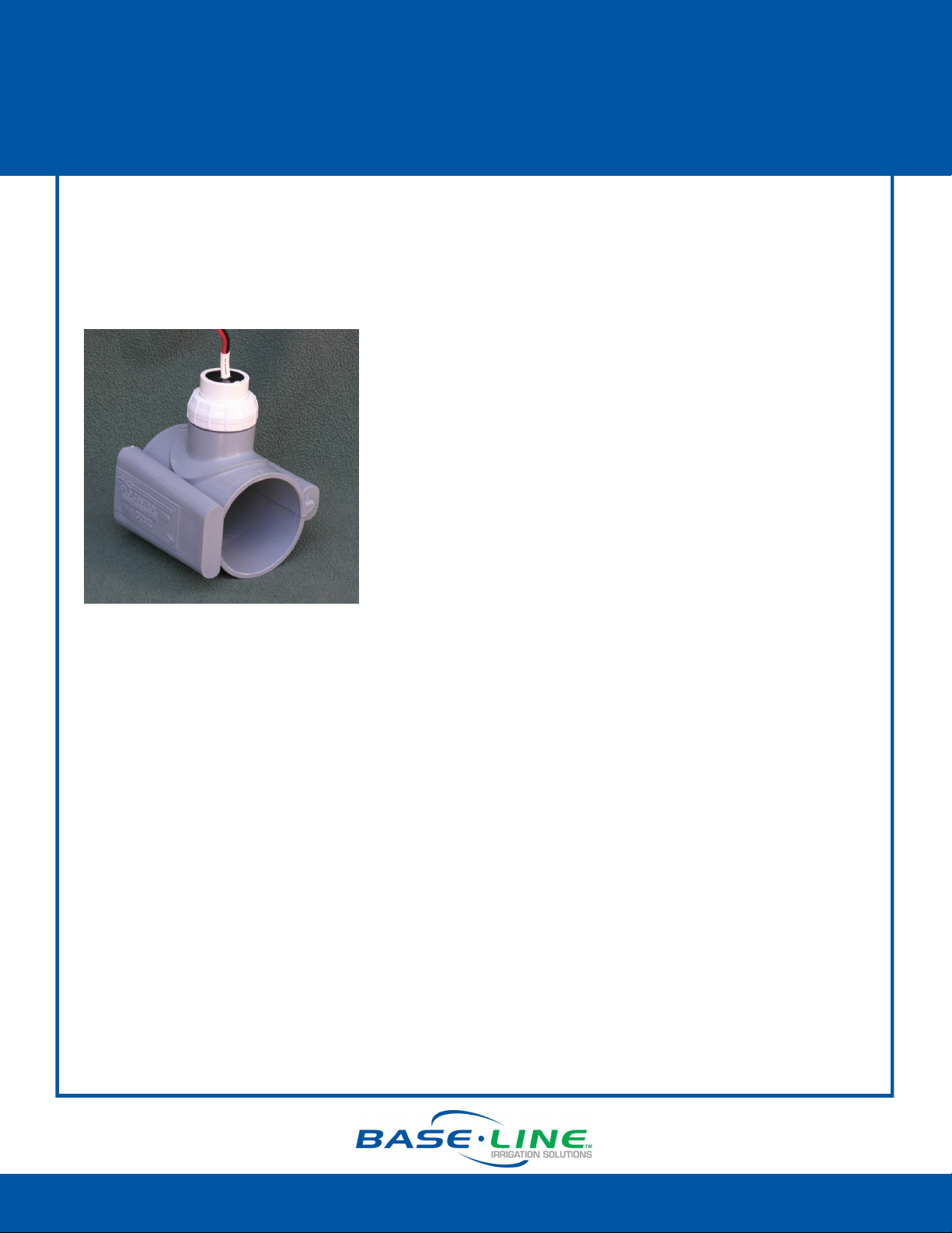
Baseline’s BL-PFS300 and BL-PFS400 are saddle-type, impeller flow sensors that provide
accurate digital output signals proportional to the velocity of the liquid flowing through the
pipe.
Installation Overview
1. Choose the proper location and orientation.
2. Install the sensor in the pipe.
3. Make the electrical connections.
4. Program the controller.
Operation Notes
Make sure the flow sensor is assembled and the retaining nut is tightened (hand tight)
before pressurizing the system.
Fill the pipeline and eliminate all trapped air.
The flow sensor should begin transmitting flow immediately; however, it may take up to
a minute for the flow readings to display in the appropriate screens on the BaseStation
controllers.
Always wait for flow to stabilize before setting control limits. Stabilization may take
several minutes in large piping systems.
1-866-294-5847 Rev 03262013 www.baselinesystems.com
Page 2
BL-PFS300 & BL-PFS400
Flow Sensor Installation
Choosing the Proper Location and Orientation
Because Baseline’s PFS flow sensor measures the velocity of the liquid and converts it to a flow
measurement based on area, proper flow measurement depends on the condition of the pipe
interior and the sensor’s location in the piping system. The pipeline must be full, free from trapped
air, floating debris and built up sediment.
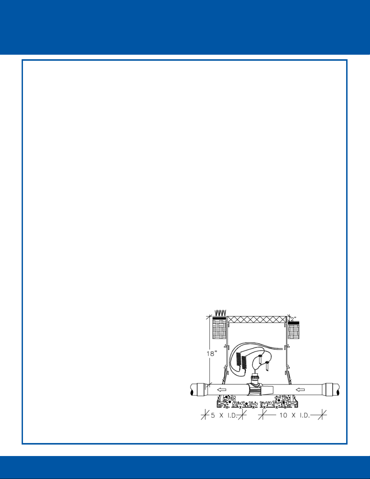
The mounting saddle should be installed with a minimum of 10 diameters of straight pipe (for
example, 30 inches for 3 inch pipe) upstream and a minimum of 5 diameters of straight pipe
(for example, 15 inches for 3 inch pipe) downstream to eliminate irregular flow profiles
caused by valves, fittings or pipe bends.
Always install with the flow arrow on the sensor pointed downstream. Allow 3 ¾” clearance to
remove the PFS flow sensor insert from the saddle for service. The saddle is usually installed
with the housing up in the vertical or 12:00 o’clock position. However, if necessary, it may be
installed with sensor housing at an angle from vertical to provide clearance.
Baseline’s PFS flow sensors may be installed inside a building, outside above grade or
underground. If installed above grade, provide adequate security to prevent damage or
disassembly. If installed below grade, provide access for service.
Baseline’s PFS flow sensors are most typically installed below grade in a horizontal section of
pipe with the sensor housing up. Do not direct bury the flow sensor. Provide a meter pit or
valve box of adequate size and drainage to service the sensor. Provide a service loop in the
wire connections to allowing the sensor housing to be brought above grade.
Baseline’s PFS flow sensors may be
installed on vertical sections of pipe
providing that the piping is full and
does not contain trapped air. A
vertical pipe with rising flow is
preferred over falling flow. The
sensor housing may be oriented in
any direction radially around the
pipe.
1-866-294-5847 Rev 03262013 www.baselinesystems.com
Page 3

BL-PFS300 & BL-PFS400
Flow Sensor Installation
Installing the Baseline PFS Flow Sensor in the Pipe
Important!
Depressurize and drain the pipe before installing the sensor.
Disassemble the PFS Flow Sensor
1. Turn the retaining nut on the PFS flow sensor insert counterclockwise and pull the insert housing straight out of the tee.
Do not pull on the wire leads!
2. Remove the tapered wedge from the side of the saddle
and fold the bottom half of the saddle down to separate it
at the hinge.
Prepare the Pipe
Attach the PFS flow sensor to the outside of a section of PVC pipe with the same nominal size as
the saddle after an entry hole for the sensor insert has been drilled through the pipe. Use best
industry practices to insure that the sensor is installed correctly.
1. Locate a straight section of pipe with a minimum of 15 diameters of straight pipe. Clean a
12” (minimum) section of pipe 10 diameters downstream of any valve, fitting, or change in
size.
2. Use a 1 ¾” hole saw, NEITHER SMALLER NOR LARGER, to drill the entry hole in the center of the
cleaned area of the empty depressurized pipe. Make sure the hole is perpendicular to the
pipe and centered. Remove the pipe coupon with the saw; do not allow it to fall into the
pipe. Remove the burr from the edge of the hole.
1-866-294-5847 Rev 03262013 www.baselinesystems.com
Page 4

Attach the Saddle to the Pipe
O-Ring
BL-PFS300 & BL-PFS400
Flow Sensor Installation
1. Make sure the o-ring seal is in place on the underside of the
saddle around the protruding sensor housing.
2. Place the top half of the saddle with the
alignment slot inside the sensor housing on
the downstream side over the pipe so that
the mount fits into the drilled hole.
Mount
3. Attach the bottom half of the saddle to the top half on the
hinged side of the top half and close it around the pipe.
4. Push the larger end of the tapered wedge over the guides. Slide
it until the pieces of the saddle are clamped together. The
wedge should go on about halfway by hand. Finish setting the
wedge by tapping it a couple times with a rubber mallet.
5. Position the flow sensor insert so the arrow is pointing
downstream, and make sure that the key is aligned with the slot
inside the housing.
6. Push the insert straight in until the o-ring seals the opening.
7. Slide the retaining nut over the wire leads and turn the nut
clockwise by hand until it is tight.
1-866-294-5847 Rev 03262013 www.baselinesystems.com
Page 5

BL-PFS300 & BL-PFS400
Flow Sensor Installation
Making the Electrical Connections
1. Power off the two-wire when installing devices. Leave 24 to 36 inches of slack on the two-wire
to allow the PFS flow sensor housing to be removed from the tee and brought above grade
for servicing.
2. Connect the red and black wire from the PFS flow sensor to the corresponding red and black
wires on the two-wire. It is critical that polarity is maintained. Do not connect flow sensor to
power or valve circuits!
3. Use wire nuts for your initial connections. After you verify communications between the
BaseStation and the PFS flow sensor, replace the wire nuts with DBR/Y or equivalent moistureresistant connectors for all two-wire path connections.
Programming the Controller
In the BaseStation 1000 User Manual, refer to Setting Up Flow biCoders. If you want the PFS flow
sensor to be associated with a water source, refer to Assigning a Flow Sensor to a Water Source.
In the BaseStation 3200 User Manual, refer to Searching for and Assigning Flow Meters. If you
want the PFS flow sensor to be associated with a water source, refer to Assigning Devices to
Water Sources.
BL-PFS300 & BL-PFS400 — Calibration Table
Model K Value Offset
PFS300 2.75 1.58
PFS400 4.53 1.11
1-866-294-5847 Rev 03262013 www.baselinesystems.com
 Loading...