

Page 1
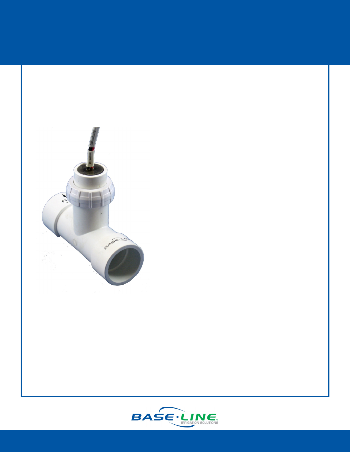
BL-PFS100, BL-PFS150, & BL-PFS200
Two-Wire Ready Flow Sensor Installation
Baseline’s BL-PFS100, BL-PFS150, and BL-PFS300 are PVC tee-type, impeller flow sensors that
provide accurate digital output signals proportional to the velocity of the liquid flowing
through the pipe.
Installation Overview
1. Choose the proper location and
orientation.
2. Install the sensor in the pipe.
3. Make the electrical connections.
4. Program the controller.
Operation Notes
Make sure the flow sensor is assembled and the retaining nut is tightened (hand tight)
before pressurizing the system.
Fill the pipeline and eliminate all trapped air.
The flow sensor should begin transmitting flow immediately; however, it may take up to
a minute for the flow readings to display in the appropriate screens on the BaseStation
controllers.
Always wait for flow to stabilize before setting control limits. Stabilization may take
several minutes in large piping systems.
1-866-294-5847 Rev 03262013 www.baselinesystems.com
Page 2
BL-PFS100, BL-PFS150, & BL-PFS200
Two-Wire Ready Flow Sensor Installation
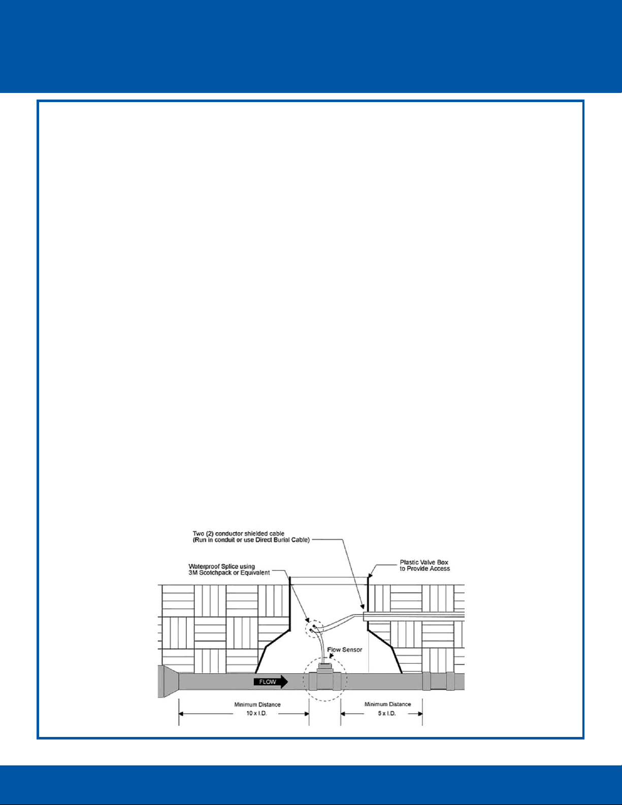
Choosing the Proper Location and Orientation
Because an impeller sensor measures the velocity of the liquid and converts it to a flow
measurement based on area, proper flow measurement depends on the condition of the pipe
interior and the sensor’s location in the piping system. The pipeline must be full, free from trapped
air, floating debris and built-up sediment.
The mounting tee should be installed with a minimum of 10 diameters of straight pipe (15
inches for 1½ inch pipe), upstream and a minimum of 5 diameters of straight pipe (7½ inches
for 1½ inch pipe) downstream to eliminate irregular flow profiles caused by valves, fittings or
pipe bends.
Always install with the flow arrow on the mounting tee pointed downstream.
Allow 3¾” clearance to remove the flow sensor housing from the tee for service. The tee is
usually installed with the housing up in the vertical or 12 o’clock position. However, if
necessary, it may be installed with sensor housing at an angle from vertical to provide
clearance.
Flow sensors may be installed inside a building, outside above grade or underground. If
installed above grade, provide adequate security to prevent damage or disassembly. If
installed below grade, provide access for service.
Flow sensors are most typically installed below grade in a horizontal section of pipe with the
sensor housing up. Do not direct bury the flow sensor. Provide a meter pit or valve box of
adequate size and drainage to service the sensor. Provide a service loop in the wire
connections to allow the sensor housing to be brought above grade.
Flow sensors may be installed on vertical sections of pipe providing that the piping is full and
does not contain trapped air. A vertical pipe with rising flow is preferred over falling flow. The
sensor housing may be oriented in any direction radially around the pipe.
1-866-294-5847 Rev 03262013 www.baselinesystems.com
Page 3

BL-PFS100, BL-PFS150, & BL-PFS200
Two-Wire Ready Flow Sensor Installation
Installing the Sensor in the Pipe
The PVC flow sensor tee features socket ends intended for solvent welding into PVC piping systems. Use
best industry practices to ensure that the sensor is installed in the correct position with strong permanent
joints.
1. Disassemble the flow sensor before joining the tee to the piping system. To
remove the flow sensor housing from the tee turn the retaining nut counter
-clockwise to loosen it, and then pull the housing straight out of the tee.
Do not pull on the wire leads!
3. Use appropriate tools to cut the pipe. Remove all chips, filings, or cuttings
from the pipe.
4. Solvent weld the tee to the pipe using manufacturer’s recommendations.
5. After the joints have set, reattach the sensor housing to the tee. Make sure
the housing and tee are clean and free from dirt or debris. Position the
arrow on the top of the housing in the downstream direction. This aligns
the guide key on the housing with the slot inside the tee. Push straight in so
that the key enters the slot until the o-ring seals the opening.
6. Slide the retaining nut over the wire leads and turn clockwise by hand to
tighten.
Do not use sealant or Teflon tape on the retaining nut
threads!
Making the Electrical Connections
1. Power off the two-wire when installing devices. Leave 24 to 36 inches of slack on the two-wire to allow
the PFS flow sensor housing to be removed from the tee and brought above grade for servicing.
2. Connect the red and black wire from the PFS flow sensor to the corresponding red and black wires on
the two-wire. It is critical that polarity is maintained. Do not connect flow sensor to power or valve
circuits!
3. Use wire nuts for your initial connections. After you verify communications between the BaseStation
and the PFS flow sensor, replace the wire nuts with DBR/Y or equivalent moisture-resistant connectors
for all two-wire path connections.
Programming the Controller
In the BaseStation 1000 User Manual, refer to Setting Up Flow
biCoders. If you want the PFS flow sensor to be associated
with a water source, refer to Assigning a Flow Sensor to a
Water Source.
In the BaseStation 3200 User Manual, refer to Searching for
and Assigning Flow Meters. If you want the PFS flow sensor to
be associated with a water source, refer to Assigning
Devices to Water Sources.
BL-PFS100, BL-PFS150 & BL-PFS200
Calibration Table
Model K Value Offset
PFS100
PFS150
PFS200
0.322
0.650
1.192
0.20
0.75
0.94
1-866-294-5847 Rev 03262013 www.baselinesystems.com
 Loading...