

Page 1

BL-CX-LA
High Gain Antenna
Lightning Arrestor Installation Guide
Installation Instructions
Note: Review the entire guide before beginning the installation.
1. Position the antennas in line of sight to each other to ensure
the best reception. Keep the antenna clear from metal walls
and surfaces.
2. Attach the antenna mount to a ridged 1.25” to 1.75”
diameter pole.
3. Route the antenna coaxial (coax) cable from the antenna
to the radio unit.
4. Use a lightning arrestor and a single point ground to help
protect equipment.
Imp ort ant !
Sin gl e p o in t g rou ndi ng is th e m ost
imp ort ant as pe ct of a g rou ndi ng sc he me
and is th e key to pr ote cti ng you r equ ipm ent
fro m e lec tro ma gn eti c p ul se (EM P) sur ge
and li ght nin g dam age .
1-866-294-5847 Rev 06182013 www.baselinesystems.com
Page 2
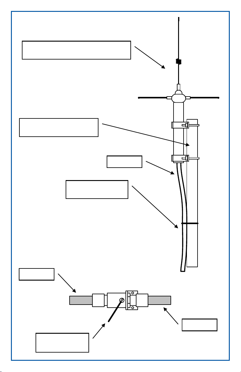
Antenna above surrounding structures
Coax Coax
with unobstructed path to other radios
Antenna mast 1.25” to 1.75”
diameter
Tie-wrap coax along
antenna mast
Coax
To Radio
To “Single Point”
system ground
Lightning Arrestor
To Antenna
Page 3

Lightning and Surge Protection
Lightning strikes are typically pulsed DC, but there is also an RF
component at about 2.2MHz. The first pulse averages 18kA.
Subsequent pulses are usually about half that. An average
lightning strike consists of 3 to 4 pulses.
Antenna and equipment should be connected to a single point
earth ground. The best ground is an 8 ft or longer copper rod
driven into the soil. Alternate grounds are (in order of decreasing
effectiveness): building steel or rebar, cold water pipe, metal
building skin, or electrical system ground.
With pole and tower grounding, use copper braid or strapping for
maximum energy dispersion.
Ground all coax cable at the antenna and where the cable
leaves the tower or mounting pole. If the antenna mounting pole
is properly grounded, then the antenna and coax are grounded
via the antenna mounting bracket system. The coax should also
be grounded as low as possible where the cable leaves the tower
or mounting pole.
Locate the lightning arrestor as close to the radio equipment as
possible.
Ground the lightning arrestor using an AWG #8 wire and crimping
or soldering to the wire lug. The other side of the wire should be
connected to a solid earth ground. The connection point for the
ground wire should always be closer to the single point earth
ground than the radio equipment grounding location.
Ground all of the components mentioned above together to a
common node (such as the antenna mast) if each is a short
distance away. This reduces the possibility of ground loops
through different earth grounds. However, if the distance from the
grounding point to the common node is greater than 20 ft, it may
be better to use separate earth grounds. Test the voltage at each
earth ground node to ensure ground potentials are equal.
Waterproof all connections using a good waterproofing tape
such as a self-annealing rubber tape. Use an outer coating of
high quality vinyl electrical tape. Apply the tape in a spiral pattern
so the overlaps will act as shingles to shed water.
Use DBR/Y or equivalent connectors for all wire connections.
Page 4

BL-CX-LA
High Gain Antenna
Lightning Arrestor Installation Guide
Recommended Tools and Materials
Tools as needed for mounting hardware (drill, screwdriver,
level, pliers, marker, tape measure, etc.)
Tools and materials as needed for installing the mounting
pole (cement, cutter, etc.)
Miscellaneous tools including hammer and screwdriver
Electrical power connection hardware (conduit, wire,
DBR/Y (or equivalent) connectors, wire nuts, etc.) and
related tools as needed
Follow local electrical codes and practices!
1-866-294-5847 Rev 06182013 www.baselinesystems.com
 Loading...