

Page 1
N E T A F I M U S A
Hydrometers
OPERATION AND
MAINTENANCE MANUAL
NETAFIM USA
5470 E. Home Ave. • Fresno, CA 93727
888.638.2346 • 559.453.6800
FAX 800.695.4753
www.netamusa.com
Page 2

This manual is intended for use by the users of this equipment. The information
contained herein is the property of Netam USA and may not be copied, used, or
disclosed to others without the manufacturer’s prior written approval.
Users are cautioned that the material contained herein is subject to change by the
manufacturer at any time and without prior notice. The material in this manual is
intended for informational purposes only.
Page 3

Table of Contents
INTRODUCTION
General Description ............................................................ 4
Water Meter/Registers .........................................................4
Hydraulic Valve (Flow Sensor) ...........................................4
Specications and Dimensions ........................................... 5
Netam USA Hydrometers with Electrical Output ............ 7
Electrical Output Specications (Reed Switch Reg.) ......... 7
Transducer Type ................................................................ 10
Hydrometer Internal Components .....................................12
MAINTENANCE PREPARATION
Preliminary Steps ..............................................................23
Tools .................................................................................. 23
MAINTENANCE 1 ½” – 8” HYDROMETERS
Hydrometer Removal From Pipeline ................................24
Finger Strainer Cleaning and Replacement ......................25
Register Assembly Removal and Replacement ................25
INSTALLATION
A. Installation Requirements .............................................13
B. Unpacking ....................................................................13
C. Pipeline Installation ...................................................... 13
D. Preliminary Steps .........................................................13
E. Installing 1 ½” and 2” Models ......................................13
F. Installing 3” – 8” Models ..............................................13
CONTROL SYSTEM
A. Solenoid Connection ....................................................14
B. Electrical Output ..........................................................14
DRAINAGE VALVE .......................................................15
OPERATIONAL TESTING
A. To test water ow and manual operation .....................16
B. To test automatic and remote operation .......................16
OPERATIONS
A. Manual Operation ........................................................17
B. Automatic Operation ....................................................17
C. Solenoid Operation .......................................................17
TYPICAL APPLICATIONS
Pressure Sustaining ...........................................................18
Pressure Reducing .............................................................19
TROUBLESHOOTING
A. Leakage from Hydrometer Connection to Pipeline .....20
B. No Electrical Output Signal from Hydrometer ............ 20
C. Controller Indicates Water Not Flowing as Instructed .20
D. No Indication of Flow on Meter Dial ...........................20
E. Controller Indicates Valve Opening Failure .................21
F. Controller Indicates Valve Closure Failure ...................21
G. Leakage from Valves or Connectors ............................21
H. Constant Drainage from Pilot Valve ............................21
I. Excess or Insufcient Output Pressure .......................... 22
J. Excess or Insufcient Input Pressure ............................22
K. Excess or Insufcient Flow Rate .................................22
MAINTENANCE 1 ½” & 2” HYDROMETERS
Hydrometer Cover and Base Assemblies ..........................26
Diaphragm/Stem Dis-Assembly .......................................27
Base and Stem Dis-Assembly ........................................... 27
Inlet Spider and Strainer ...................................................28
MAINTENANCE 3” & 4” HYDROMETERS
Hydrometer Dis-Assembly and Re-Assembly ................... 29
Hydrometer Cover and Base Sub-Assemblies .................. 29
Diaphragm/Stem Assembly and Base Assembly ..............30
Inlet Spider and Strainer ...................................................31
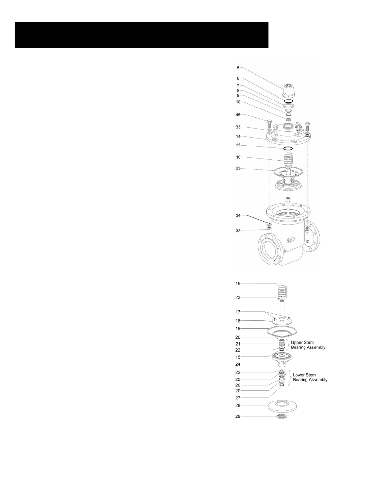
MAINTENANCE 6” HYDROMETERS
Hydrometer Dis-Assembly and Reinstallation .................32
Register ............................................................................. 32
Hydrometer Cover ............................................................32
Diaphragm and Upper Stem Bearing ................................ 33
Lower Stem Bearing and Valve Cover ..............................33
Impeller and Flow Tube Sub-Assemblies ......................... 34
Inlet Spider ........................................................................ 34
MAINTENANCE 8” HYDROMETER
Hydrometer Dis-Assembly and Re-Assembly ................... 35
Register ............................................................................. 35
Hydrometer Cover ............................................................35
Diaphragm Sub-Assembly ................................................35
Diaphragm Sub-Assembly and Dis-Assembly .................36
Lower Chamber Disc Sub-Assembly ................................36
Stem Sub-Assembly and Valve Cover ..............................37
Impellar and Flow Tube Assemblies ................................. 38
Inlet Spider ........................................................................ 38
SCHEMATICS ................................................................39
Page 4
Introduction
GENERAL DESCRIPTION
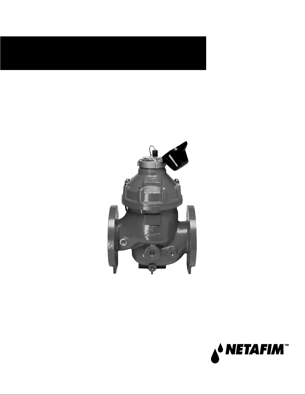
A hydrometer combines a hydraulic master valve, water meter and a
ow sensor in a single unit. Netam USA’s Hydrometer is designed
for high pressure, remote control irrigation and industrial applications.
Body: Horizontal
Available Sizes: 1½”, 2”, 3”, 4”, 6” and 8”
Operation: For automatic and remote operation in a variety
of applications. Remote operation is possible via
an external solenoid valve activated by a remote
controller or control center. Flow rate and volume
data are electronically transmitted to the remote
controller by means of a transducer inserted into
the register dial.
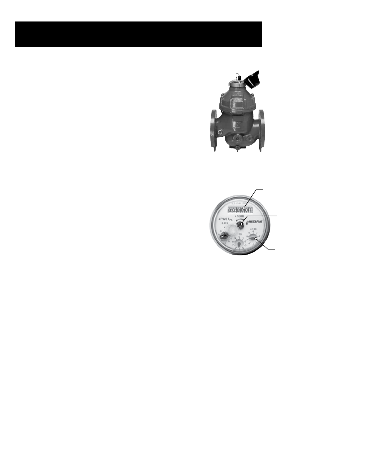
WATER METER/REGISTERS
The hydrometer contains both a dry contact (reed switch) type
magnetic drive and a higher frequency output photo-diode register
transmission water meter, the impeller is the only moving part in
contact with the water. The meter may be calibrated to measure either
gallons or cubic meters. A hermetically sealed register contains the
dial face and all mechanical meter components.
The dial face contains:
• Totalizer
• Three (3) analog pointers
• Rotating ow indicator or leak detector
A magnetic pointer, located over one of the analog pointers, measures
the ow rate and transmits the data to the reed switch transducer in
the register cover.
HYDRAULIC VALVE (FLOW SENSOR)
The hydrometer contains a hydraulic master valve operated either
manually or by remote control. The valve normally remains closed
until a command is received to open it. Hydraulic commands
are transmitted to the valve via an external solenoid valve. The
hydrometer can also be ordered in a Normally Open conguration.
In this case the valve is opened until a command is received and the
valve closes.
Standard Register
Gallon Totalizer
Totalizer
Analog Pointers
Rotating Flow
Indicator or
Leak Detector
4 • Hydrometers Operation and Maintenance Manual
Page 5

Specications and Dimensions
W L
H
SPECIFICATIONS
Size 1 ½”
Maximum Working Pressure (psi) 230 230 230 230 230 230
Minimum Working Pressure (psi) 14 14 14 14 14 14
Regulated Pressure Ratio 1:3 1:3 1:3 1:3 1:3 1:3
Maximum Flow Rate (GPM) 55 95 220 380 860 1500
Minimum Flow Rate (GPM) 4.4 20 53 79 198 357
Accuracy ±2% ±2% ±2% ±2% ±2% ±2%
2”
3” 4” 6” 8”
H
W
W L
L
H
Hydrometer Dimensions
Size 1 ½”
Length (L) 6 5/16” 6 1/4” 9 9/16” 10 15/16” 19 1/2” 20 11/16”
Width (W) 4 3/4” 4 3/4” 8 1/4” 9 1/16” 14 7/8” 17 3/4”
Height (H) 10 5/16” 13 13/16” 16 15/16” 17 3/4” 25 7/16” 25 5/8”
Weight 4 lbs. 7 lbs. 52 lbs. 65 lbs. 245 lbs. 309 lbs.
2”
3” 4” 6” 8”
Hydrometers Operation and Maintenance Manual • 5
Page 6
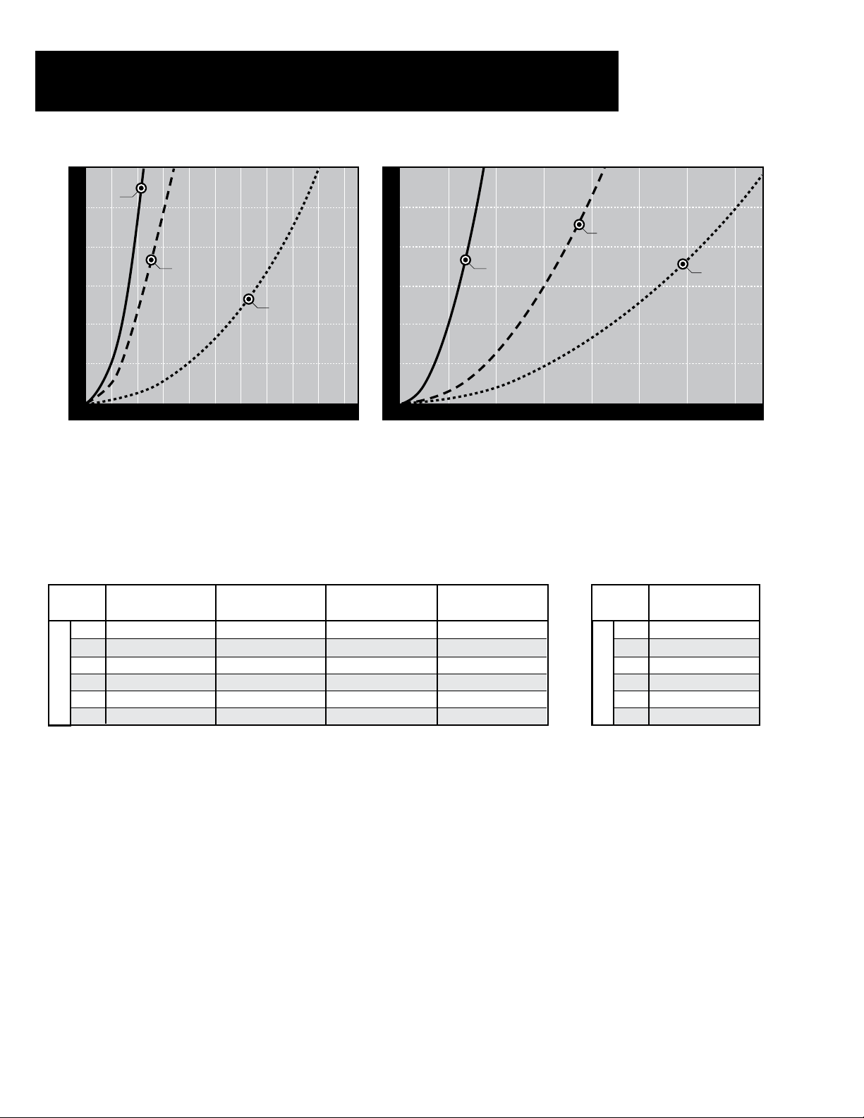
Headloss Charts
1 ½”
5.0
Specications, Cont.
5.0
4.0
2”
3.0
3”
Headloss (psi)
2.0
1.0
0
Pressure loss in psi = (gpm/Cv)
50
100 150 200 250
^2
Example: 2” Hydrometer, design ow @ 97 gpm
(55 gpm/35 gpm)
^2
= 2.5 psi headloss
Performance Data
Size
within ± 5% Accuracy
1 ½”
2”
3”
4”
6”
8”
Lowest Flow
1.8 GPM 4.4 GPM 44 GPM 55 GPM
5.3 GPM 20 GPM 66 GPM 95 GPM
14 GPM 53 GPM 176 GPM 220 GPM
21 GPM 79 GPM 264 GPM 380 GPM
53 GPM 198 GPM 660 GPM 860 GPM
97 GPM 357 GPM 1,189 GPM 1,500 GPM
Lowest Flow
within ± 2% Accuracy
4.0
3.0
Headloss (psi)
2.0
1.0
0
Nominal Flow
within ± 2% Accuracy
4”
200
within ± 2% Accuracy
400 600 800 1000 1200 1400
Maximum Flow
6”
8”
Flow Rate (gpm)Flow Rate (gpm)
Cv Values
Cv (Flow Rate at
1.0 psi of Headloss)
Size
1 ½”
2”
3”
4”
6”
8”
23 GPM
35 GPM
92 GPM
139 GPM
347 GPM
624 GPM
6 • Hydrometers Operation and Maintenance Manual
Page 7

Specications, Cont.
NETAFIM USA HYDROMETERS WITH ELECTRICAL OUTPUT
Netam USA Hydrometers are equipped with electrical output devices that combine the high reliability
of hermetically sealed, magnetically driven registers with a wide variety of electrical output options.
Hydrometers (measuring instruments) provide electrical output information about the ow of water.
When more than just the traditional register is needed, they also provide the solution for automation and
communication with controllers, electronic devices and other water delivery systems.
Netam USA has three types of transducer outputs available which provide three levels of resolution:
• Reed Switch (RS) Register - low frequency pulse output for functions related
primarily to recording volume.
• Photo Diode (PD) Register - standard frequency pulse output (open collector) for
functions such as rate of ow and recording total volume.
• Photo Diode (PDH) Register - high frequency pulse (open collector) for functions
such as rate of ow and recording total volume.
Recommended Register
Transducer Outputs
Manufacturer
Baseline Basestation PDH
Hunter ACC 2-Wire PDH
Rain Bird MDC & Maxi RS
Signature All Models RS
Sentinel PDH
Toro
TDC 2-Wire PDH
Rainmaster All Models
PD (6”, 8”)
Flowmaster
Tucor
& RK Series
Motorola All Models RS
Controller
Model
Recommended
Register Type
RS (1” to 4”)
PDH
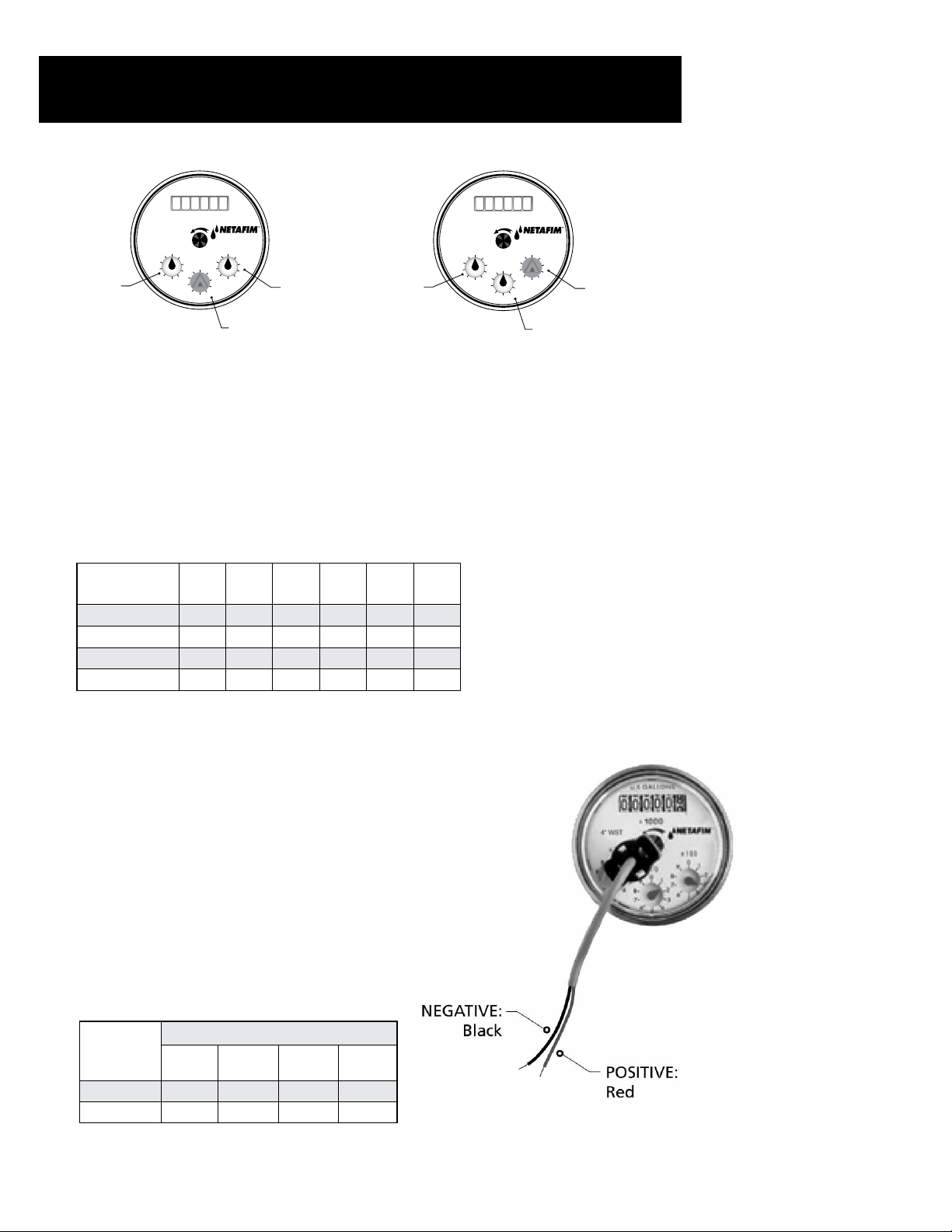
ELECTRICAL OUTPUT SPECIFICATIONS
REED SWITCH (RS) REGISTER
The ow rate is transmitted as periodic electrical pulses are measured by the magnetic pointer in
the dial face. The hydrometer is congured to transmit a pulse according to a pre-dened volume
interval. The following summarizes the available volume intervals for various hydrometer sizes in
either gallons or cubic meters.
• A three pointer register, with a magnet installed on one of the pointers.
• Output denition: Volume Output
• Output type: RS – Reed Switch and PD – Photo Diode
The sensor is installed in a transparent plastic cover that can be mounted on the register in one of
three positions with the pointer facing the magnet. Three values of electrical output are available
in 1:10:100 ratios.
Hydrometers Operation and Maintenance Manual • 7
Page 8
Specications, Cont.
U.S. GALLONS
0 0 0 0 0 0
BM
0
9
1
8
2
0
7
9
3
1
6
8
4
5
Pulse per
1 USG
EXAMPLE for sizes 1½”, 2”, 3”, 4”
(standard pulse = 1 g/p)
7
6
4
5
9
8
7
6
2
3
0
1
2
3
4
5
Pulse per
10 USG
Pulse per
100 USG
Pulse per
10 USG
U.S. GALLONS
0 0 0 0 0 0
x 1000
BM
0
9
1
8
7
6
4
5
EXAMPLE for sizes 6”, 8”
(standard pulse = 10 g/p)
0
9
1
8
2
9
3
8
7
6
2
0
7
3
1
6
4
2
5
3
4
5
Pulse per
100 USG
Pulse per
1000 USG
For sizes 1½”, 2”, 3”, 4”: If the pointer with the magnet is set in the middle position as shown
in the drawing the magnet will make one contact of the reed switch for every 360° rotation - the
result is an output of 1 pulse per 10 USG.
For sizes 6”, 8”: If the pointer with the magnet is set in the right position as shown in the drawing
the magnet will make one contact of the reed switch for every 360° rotation - the result is an
output of 1 pulse per 1000 USG.
Available Impulse Sequences
Available Outputs
(U.S. gallons/pulse)
1
10
100
1000
1 ½”
3” 4” 6” 8”
2”
Reed Switch (RS) Register
Specifications
• Magnet activated.
• Acts as a “dry contact”, uses very little
electric power.
• For “Volume” related functions such as
data recorders or simple counters.
Electrical Specifications
Maximum Contact Current: 50 mA
Maximum Contact Voltage: 28 VDC
Reed Switch (RS)
Low Frequency Pulse Outputs
Reed Switch (RS)
Hydrometer
Size
1½”, 2”, 3”, 4” 1 1 60.00 0
6”, 8” 10 0.1 600.00 0
Gallons/
Pulse
Pulse/
Gallon K Factor Offset
Circuit Diagram
Register with Reed Switch
Output, Two Wires
8 • Hydrometers Operation and Maintenance Manual
Page 9
Specications, Cont.
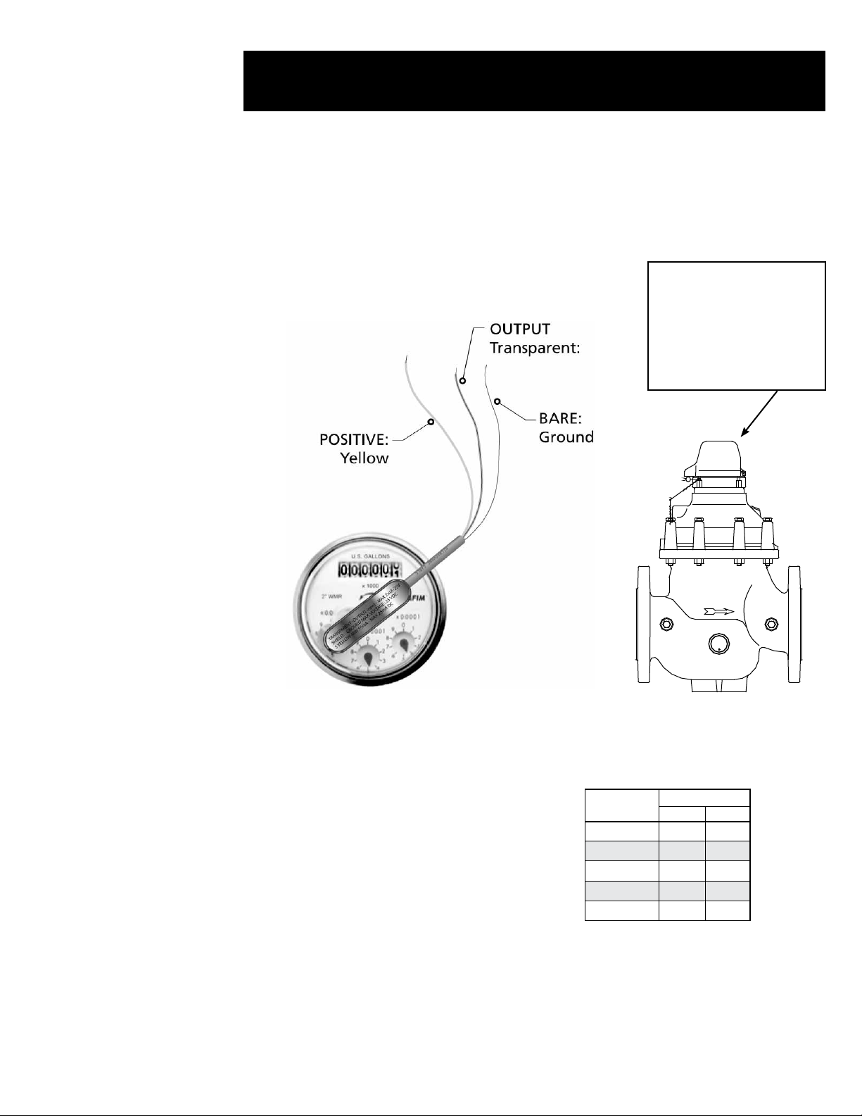
Photo-Diode (PD & PDH) Register
• SensorcombinesanIRlightsourceandalightsensitive
diode in one package.
• Signalsarecreatedwhenthelightbeamcreatedbythe
IRlightisinterruptedbyarotatingelement.
• RequiresaconstantsupplyofDCpower.
Circuit Diagram
Register with Photo Diode
Output and Wire Leads
Note:Sunlightwillinterfere
withtheIRlightandmay
corruptorinterferewiththe
signal—keepdustcapclosed
during operation to ensure
propersignaloutput.
Photo-Diode Electrical
Specifications
POSITIVE powers the IR light
(yellow wire)
Current Min: 15 mA to a maximum of 25 mA DC
through a resistor
•MaximumVoltage:28VDC
OUTPUT (clear wire)
Output–Opencollector
Recommended
Resistor Valves
Voltage (V+)
Ω W
5 180 0.25
6 220 0.25
9 330 0.25
12 470 0.50
24 1000 1.00
Resistor Values
(Max. Load – 2 mA)
GROUND (bare wire)
NOTE: Correct polarity of the leads should be
checked carefully to prevent damage to
the sensor.
Hydrometers Operation and Maintenance Manual • 9
Page 10
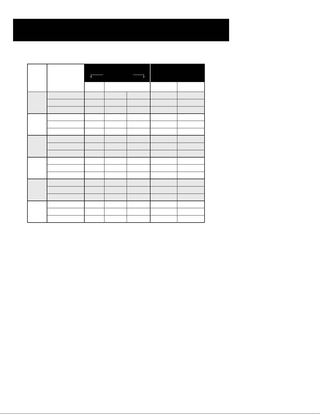
Transducer Type
Transducer Type: Reed Switch and Photo Diode K Factors
Photo Diode (PD) and
Photo Diode High Frequency
Meter
Size
1½”
2”
3”
4”
6”
8”
Reed Switch (RS)
Standard
Output
Gallons per pulse 1 10 100 0.1 0.0053
Pulse per gallon 1 0.1 0.01 10 187.900
K factor 10.00 60.00 600.00 6000.00 6.00 0.319
Gallons per pulse 1 10 100 0.1 0.0085
Pulse per gallon 1 0.1 0.01 10 117.000
K factor 10.00 60.00 600.00 6000.00 6.00 0.5100
Gallons per pulse 1 10 100 0.1 0.0205
Pulse per gallon 1 0.1 0.01 10 48.710
K factor 10.00 60.00 600.00 6000.00 6.00 1.232
Gallons per pulse 1 10 100 1 0.0556
Pulse per gallon 1 0.1 0.01 10 17.993
K factor 10.00 60.00 600.00 6000.00 6.00 3.335
Gallons per pulse 10 100 1000 1 0.1741
Pulse per gallon 0.1 0.01 0.001 1 5.747
K factor 10.00 600.00 6000.00 60000.00 60.00 10.437
Gallons per pulse 10 100 1000 1 0.317
Pulse per gallon 0.1 0.01 0.001 1 3.152
K factor 10.00 600.00 6000.00 60000.00 60.00 19.036
Optional Output PD PDH
Pulse (PDH)
Note: Offset = 0 in all Netafim USA Water Meters
When entering K factors in controllers and/or data recorders please refer to the manufacturer’s
recommendations—some will require the number of gallons per pulse and others will require
the number of pulses per gallon. Some manufacturers will require a “K” and “offset” (for all
Netam USA Water Meters the offset = 0) where the K and offset are calculated using he following equation:
Freq = (GPM/K) – offset
Where:
Freq = pulse/second
GPM = gallons per minute
K = unit less constant specic to each hydrometer pulse output
Offset = correction factor (All Netam USA water meters have an offset = 0)
or:
K = 60/(pulse/gallon)
10 • Hydrometers Operation and Maintenance Manual
Page 11

Specications, Cont.
Ordering Information
FLOW RANGE
Min GPM
PD 10 0.1
1.8 55 1½” Male Pipe Thread PDH 187.900 0.0053
RS 1 1
PD 10 0.1
5.3 95 2” Female Pipe Thread PDH 117.000 0.0085
RS 1 1
PD 10 0.1
14 220 3” Flanged PDH 48.710 0.0205
RS 1 1
PD 10 0.1
21 380 4” Flanged PDH 17.933 0.0556
RS 1 1
PD 1 1
53 860 6” Flanged PDH 5.747 0.1741
RS 0.1 10
PD 1 1
97 1,500 8” Flanged PDH 3.152 0.317
RS 0.1 10
± 5%
Max GPM
± 2%
Meter
Size
Connection
Register
Output
Type
Pulse per
Galon
Gallons
per Pulse
Electric
• LHM15TG01-MEL
• • LHM15TG01-PRMEL
• LHM15TG0053-MEL
• • LHM15TG0053-PRMEL
• LHM15TG1-MEL
• • LHM15TG1-PRMEL
• LHM2TG01-MEL
• • LHM2TG01-PRMEL
• LHM2TG0085-MEL
• • LHM2TG0085-PRMEL
• LHM2TG1-MEL
• • LHM2TG1-PRMEL
• LHM3FG01-MEL
• • LHM3FG01-PRMEL
• LHM3FG0205-MEL
• • LHM3FG0205-PRMEL
• LHM3FG1-MEL
• • LHM3FG1-PRMEL
• LHM4FG01-MEL
• • LHM4FG01-PRMEL
• LHM4FG0556-MEL
• • LHM4FG0556-PRMEL
• LHM4FG1-MEL
• • LHM4FG1-PRMEL
• LHM6FG1-MEL
• • LHM6FG1-PRMEL
• LHM6FG1739-MEL
• • LHM6FG1739-PRMEL
• LHM6FG10-MEL
• • LHM6FG10-PRMEL
• LHM8FG1-MEL
• • LHM8FG1-PRMEL
• LHM8FG317-MEL
• • LHM8FG317-PRMEL
• LHM8FG10-MEL
• • LHM8FG10-PRMEL
Model Number
Pressure
Regulating
Hydrometers Operation and Maintenance Manual • 11
Page 12
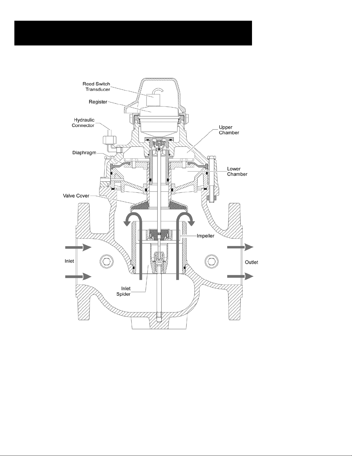
Hydrometer Internal Components
Hydrometer Internal Components
(DoubleChamberNotAvailablein6”)
12 • Hydrometers Operation and Maintenance Manual
Page 13
Installation
A. Installation Requirements
• Globe conguration hydrometers
require no straight pipe installation
requirements. Do not install valves
that will cause a restriction directly
upstream or downstream of the
hydrometer.
• Connections to the hydrometer
should be the same size as the meter.
Example: if a 3” hydrometer is
installed, 3” pipe and ttings should
Globe Configuration
Straight Pipe Installation Requirement
0 x D and 0 x D
Upstream
Size
1 ½” 0” 0” 6 5/16” 6 5/16”
2” 0” 0” 8 5/8” 8 5/8”
3” 0” 0” 11 1/2” 11 1/2”
4” 0“ 0” 14 1/8“ 14 1/8“
6” 0“ 0” 19 1/2“ 19 1/2“
8” 0” 0” 23 5/8“ 23 5/8“
Distance
Downstream
Distance
Meter
Length
Total
Requirement
be connected to the hydrometer.
• Prior to installation of the meter, the
pipeline should be thoroughly ushed.
• Recommendation: Air Vents of proper size and type, Continuous
acting and large acting, be installed to eliminate air.
B. Unpacking
The hydrometer comes fully assembled according to the customer’s specications. The 1½” model
is shipped with the appropriate couplings and gaskets. For larger diameter models installation
hardware is not included for larger diameter models. Pilot valves and other accessories are factory
installed and calibrated according to the customer’s specications.
C. Pipeline Installation
The following tools are required to perform these procedures:
• Flat blade and Phillips head screwdrivers in various sizes
• Open end or box wrenches in various sizes
• Large pipe wrenches
• Pliers
• Dies or pipe threading tools compatible with the pipeline diameter
• Teon tape or similar pipe sealing material
D. Preliminary Steps
1. Before beginning the installation, the line should be thoroughly ushed to remove any
foreign matter.
2. Close the inlet valve in order to shut off the water ow to the pipeline.
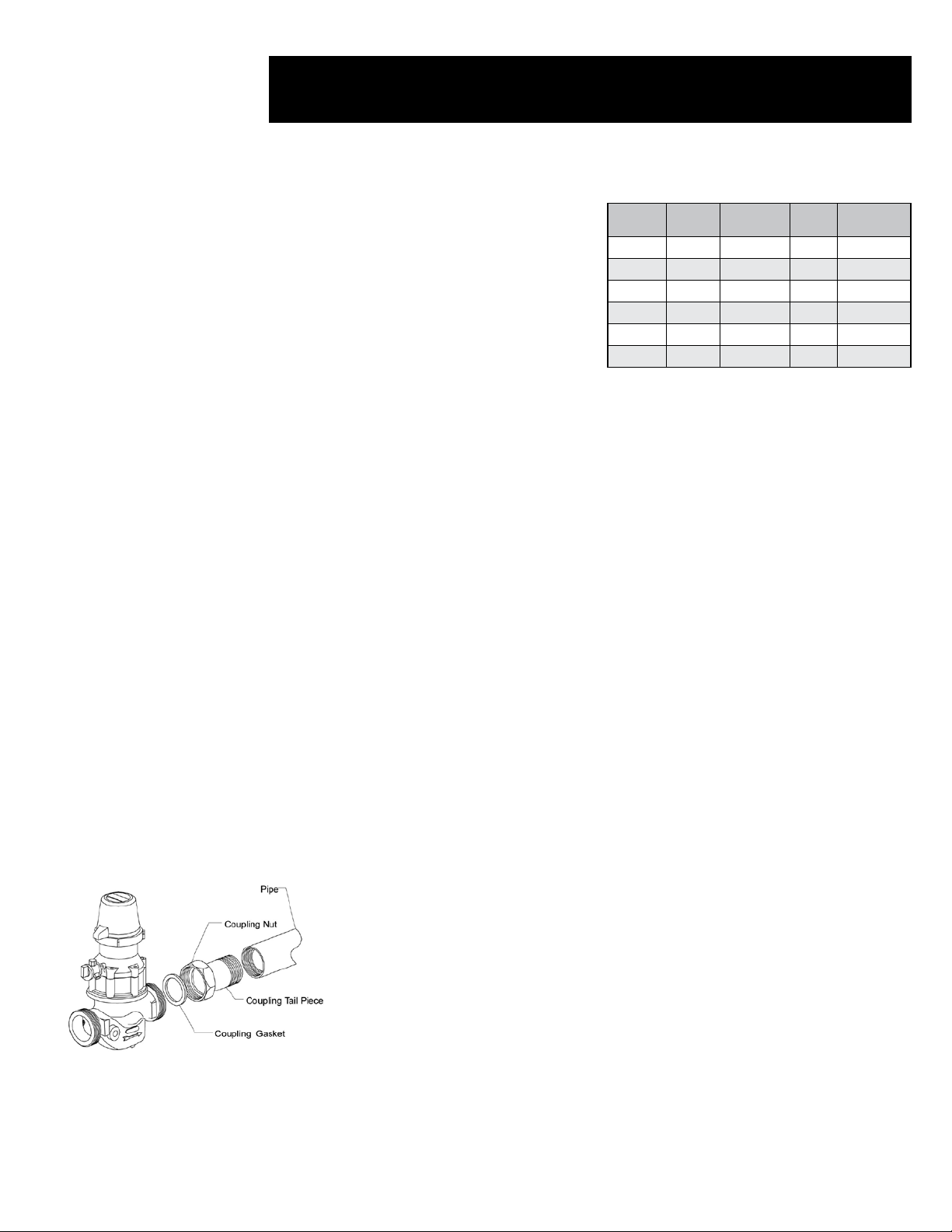
E. Installing 1½” and 2” Models
The 2” hydrometer can be attached directly to a male threaded pipeline or to a female threaded
pipeline using a coupling. The 1½” model can only be attached using a coupling.
Coupling Connection
• Create a female threaded connection on both pipe sections.
• Apply Teon tape or similar material to seal the connections.
• Insert the male coupling connections into the pipeline sections and tighten securely.
• Place a coupling gasket over each male threaded hydrometer connection and
securely tighten the coupling nuts.
Direct Connection
• Create a male threaded connection on both pipe sections that are to be attached.
• Apply Teon tape or similar material to seal the connections.
• Insert the male threaded pipe connection into the hydrometer and tighten securely.
F. Installing 3” – 8” Models
The end user is expected to supply the appropriate gaskets
and bolts according to the diameter of the pipeline.
• Place the appropriate gasket onto each ange.
• Insert the bolts, nuts and washers and tighten securely.
Hydrometers Operation and Maintenance Manual • 13
Page 14

Installation, Cont.
CONTROL SYSTEM
A. Solenoid Connection
The hydrometer receives commands from the controller or control center via an external solenoid
valve. The hydrometer may be ordered with a factory installed solenoid valve or connected to an
solenoid valve supplied by the user.
To connect to a factory installed solenoid:
1. Connect the electric cable from controller to the attached solenoid valve. Position
the three-way selector in the “Auto” position - in this position the hydrometer will be
controlled by the solenoid.
B. Electrical Output
The hydrometer supplies volume and ow rate data to a controller or to an external measuring
device via an electrical connection. A reed switch transducer is factory installed in the register
dial. The cable attached to the reed switch transducer attaches to the controller or measuring
device.
To connect the hydrometer to the controller or measuring device:
1. Install an appropriate connector onto the bare end of the cable exiting from the reed
switch. Refer to the user manual of the controller or measuring device for details
regarding the specic connector type.
2. Connect the cable to the input port of the controller or measuring device.
(See pages 7-10 for more details)
14 • Hydrometers Operation and Maintenance Manual
Page 15
Drainage Valve
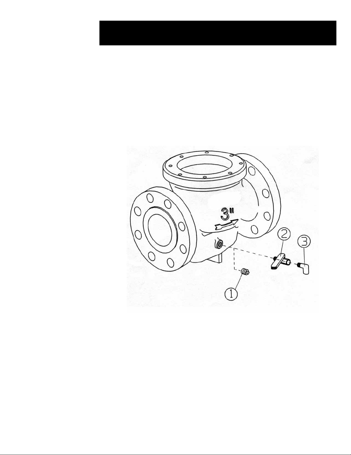
DRAINAGE VALVE
At the beginning of the winter it is necessary to drain the water from the pipeline in order to
prevent the pipes from bursting. (Please refer to the drawing below)
• Before draining, it is very important to ensure that there is no pressure in the line.
• Dissassemble plug (1)
• Assemble the drainage ball valve (2)
• Assemble elbow (3)
CAUTION: Do not use compressed air to blow out hydrometer.
Hydrometers Operation and Maintenance Manual • 15
Page 16

Operational Testing
INSTALLATION
Before the hydrometer is placed into service, you should perform the following tests to verify that
it is operating properly:
A. To test water ow and manual operation:
• Set 3-Way Selector to the “Open position”.
• Turn on the water ow to the hydrometer.
• Visually verify that water is owing downstream from the hydrometer in appropriate
quantities.
• Verify that the leak detector, pointers and the totalizer are functioning properly.
• Check all hoses, connections, pilot valves, etc. for leakage and repair as necessary.
• Set 3-Way Selector to the “Close position”.
• Verify that the water ow downstream has stopped.
B. To test automatic and remote operation:
• Set 3-Way Selector to the “Auto” position.
• Turn on the water ow to hydrometer.
• Verify that the hydrometer output is correctly received by the controller or control center.
• Use the controller or control center to close the hydrometer. Verify that the water ow
downstream has stopped.
• Use the controller software to test operation of the hydrometer under various applications
and conditions such as pressure reducing, pressure sustaining and ow regulation.
• Your hydrometer is now ready for routine use.
16 • Hydrometers Operation and Maintenance Manual
Page 17
3-Way Selector
SOLENOID
Operations
The hydrometer is designed to operate in a variety of automatic and remote control applications.
The hydrometer valve is also capable of manual operation and the register dial may be read as an
ordinary water meter.
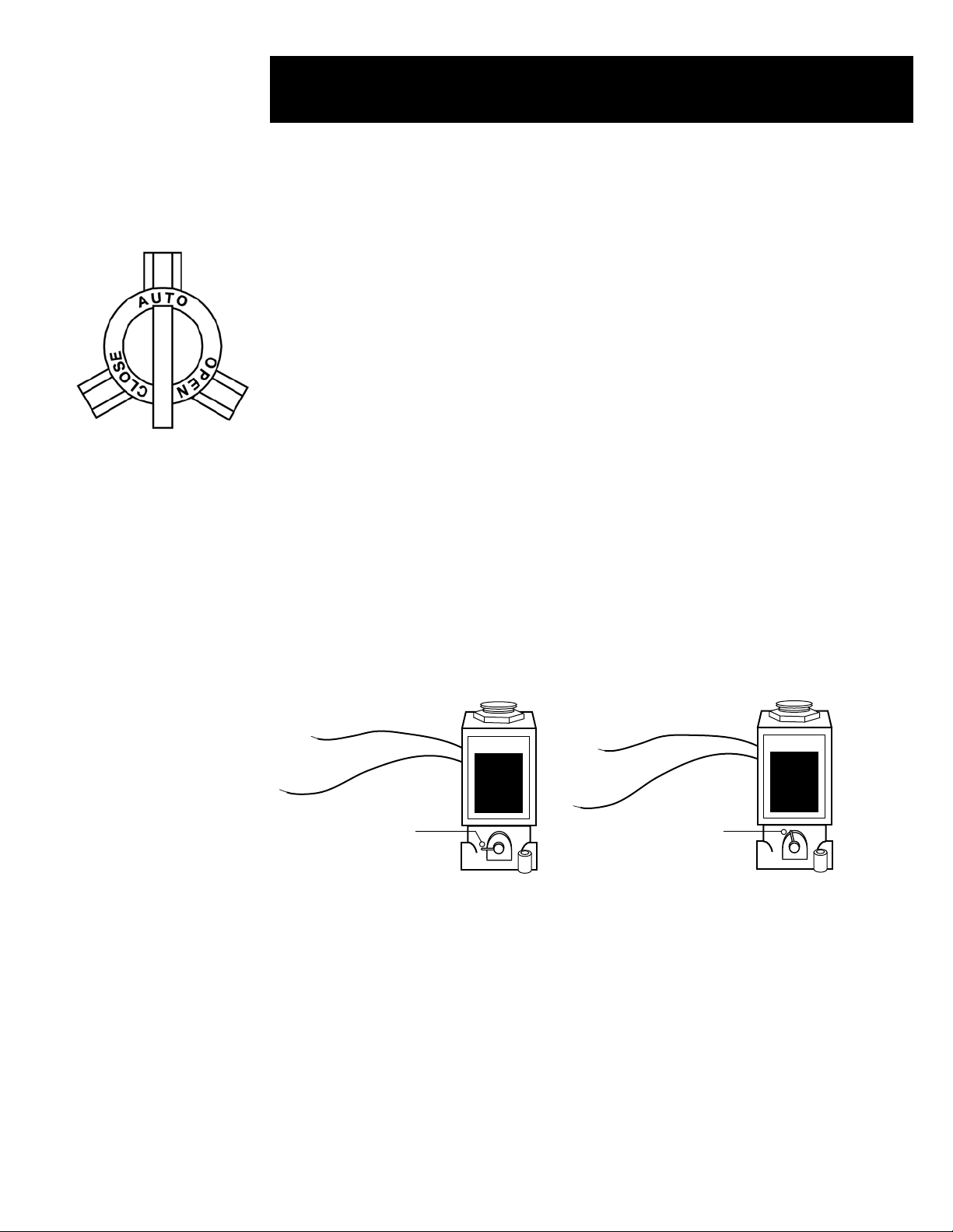
A. Manual Operation
The hydrometer may be manually operated using the 3-Way Selector:
• To manually open the valve: Rotate the 3-Way Selector to the “Open” position.
• To manually close the valve: Rotate the 3-Way Selector to the “Close” position.
B. Automatic Operation
Automatic operation is made possible by direct hydraulic control from a remote controller or
control center. Volume and/or ow data is electronically transmitted to the remote controller
by means of a reed switch transducer. The command to open or close the hydrometer valve is
transmitted from the controller to a solenoid, which, in turn, transmits a hydraulic command to the
hydrometer.
Automatic operation may also be based on a pre-set pressure or ow rate by the use of one or
more Pilot Valves. To enable automatic and/or remote operation, rotate the 3-Way Selector to the
“Auto” position.
C. Solenoid Operation
The hydrometer is always controlled via an external solenoid valve. A “normally open” (NO),
high pressure, 3-Way solenoid valve is required for this purpose resulting in a normally closed
hydrometer. When a normally closed solenoid is used it will result in a normally open hydrometer.
An electric cable connects the controller and the solenoid valve. 8 mm polyethylene tubing runs
from the solenoid valve to the “Auto” connection on the 3-Way Selector.
SOLENOID
Open
Manual Override
Automatic
Position
SOLENOID
Open
Position
Automatic Position
Operated by the Controller
Electric Solenoid Specications
• Operation:
– Solenoid: 24vac 5.5 watts,
0.23 amps inrush
– Manual Override
• Construction: Brass
• Connections: In/Out NPT Threaded
Hydrometers Operation and Maintenance Manual • 17
Page 18
Typical Applications
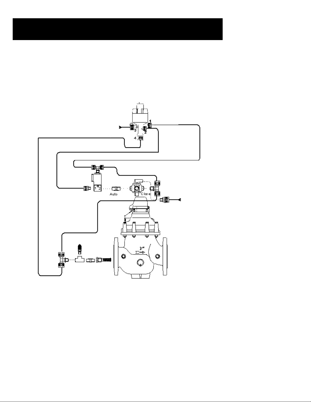
PRESSURE SUSTAINING
The pressure sustaining operation prevents the input pressure from falling below a predetermined
value. This application requires a Netam Pressure Regulating Pilot Valve, or comparable valve.
Rotate the adjusting screw atop the pilot valve counterclockwise to increase the desired input
pressure and clockwise to reduce the desired input pressure.
Connection Information
The sensor connection runs from the input connector on the hydrometer to the controlled input
connector (1) on the pilot valve. The sensor connection also branches off to the “Close” connector
on the 3-Way Selector and to the vent connector (4) on the pilot valve.
The command connection runs from solenoid to the “Auto” connector on the 3-Way Selector
(via the shuttle valve) and continues on to the pressure controlled input connector (2) on the pilot
valve.
The supply connector (3) on the pilot valve serves as a vent. The output connector on the
hydrometer is not used.
18 • Hydrometers Operation and Maintenance Manual
Page 19

Typical Applications, Cont.
PRESSURE REDUCING
The pressure reducing operation prevents the output pressure from increasing above a
predetermined value. This application requires a PC Pressure Regulating Pilot Valve, or
comparable valve. Rotate the adjusting screw on top of the pilot valve counterclockwise to
increase the desired output pressure and clockwise to reduce the desired output pressure.
Connection Information
The sensor connection runs from the output connector on the hydrometer to the pilot valve
controlled input connector (1).
The pressure supply connection runs from the hydrometer input connection to the pilot valve
supply connector (3). This connection branches off to the “Close” connection on the 3-Way
Selector.
The command connection runs from solenoid to the “Auto” connector on the 3-Way Selector and
continues on to the pressure controlled input connector (2) on the pilot valve.
The vent connector (4) on the pilot valve serves as a vent.
Hydrometers Operation and Maintenance Manual • 19
Page 20

Troubleshooting
This chapter provides detailed troubleshooting procedures and solutions for a variety of
common problems. The procedures described below are general in nature and are presented in
a “Quick Reference” style outline format.
We recommend that you perform the steps in order until the specic problem is solved. It may
not be necessary to complete all of the steps in a given procedure.
A. Leakage from Hydrometer Connection to Pipeline
• Inspect and tighten the couplings or ange bolts. Replace the coupling, bolts and nuts
as necessary.
• Apply Teon tape, or other similar material, to seal the connection.
• Inspect and replace gaskets as necessary.
• Inspect and clean the orice and associated gaskets (ow control applications only).
Replace as necessary.
B. No Electrical Output Signal From Hydrometer
• Inspect all cables and electrical connections. Repair or replace cables as necessary.
• Verify that the reed switch transducer is properly inserted into the register dial.
• Verify that the controller is functioning properly. If not, restart the controller and make
certain that your software is properly congured.
• Replace the reed switch transducer.
• Verify that the ow indicator on the meter dial is rotating.
C. The Controller Indicates Water is Not Flowing as Instructed
• Verify that the controller is functioning properly. If not, restart the controller and verify
that your software is properly congured.
• Move the 3-Way Selector to the “Open” position. Check to see if the controller shows
water ow. If so, this indicates that the solenoid is not functioning properly. Repair or
replace as necessary.
• Verify that the reed switch transducer is properly inserted into the register dial.
• Check all electrical connections. Replace cables as necessary.
• Verify that the ow indicator on the meter dial is rotating.
D. No Indication of Flow on Meter Dial
• Remove the register assembly as described on page 25. Place a small magnet on the
bottom of the register assembly and move it in a circular motion. This should cause the
ow indicator to rotate freely. If it does not, replace the register.
• Disassemble the hydrometer as described in Chapter 5.
• Clean or replace the strainer (1½” and 2” models only).
• Verify that the impeller rotates freely. If it does not, inspect the impeller, impeller shaft
and other related components. Replace as necessary.
• Inspect the diaphragm and o-rings. Replace as necessary.
20 • Hydrometers Operation and Maintenance Manual
Page 21

Troubleshooting, Cont.
E. Controller Indicates Valve Opening Failure
• Verify that the 3-Way Selector is in the “Auto” position. If it is not, turn the switch to the
“Auto” position and then check to see if the controller indicates that the valve is open.
• Verify that the controller and your software are functioning properly. If not, restart the
controller and make certain that your software is properly congured.
• Verify if there is water ow downstream from the hydrometer. If there is not, this indicates
that the valve is indeed closed.
• Check the electrical connections as described on page 8.
• Check the register as described in the rst step on page 5.
• Remove the 3-Way Selector. Clean or replace as necessary.
• Verify solenoid operation. Repair or replace as necessary.
• Disassemble the hydrometer as described in the Maintenance section, pages 23-38.
• Clean or replace the strainer (1½” and 2” models only).
• Inspect the diaphragm and o-rings. Replace as necessary.
F. Controller Indicates Valve Closure Failure
• Verify that the 3-Way Selector is in the “Auto” position. If it is not, turn the switch to the
“Auto” position and then check to see if the controller indicates that the valve is open.
• Verify that the controller and your software are functioning properly. If not, restart the
controller and make certain that your software is properly congured.
• Move the 3-Way Selector to the “Close” position. Check to see if the controller indicates
that the valve is closed. If so, this indicates that the solenoid is not functioning properly.
Repair or replace as necessary.
• Verify if there is water ow downstream from the hydrometer. If there is, this indicates that
the valve is indeed open.
• Check the electrical connections as described on page 7.
• Check the register as described in the rst step on page 4.
• Remove the 3-Way Selector. Clean or replace as necessary.
• Remove and clean the nger strainer. Replace if necessary.
• Disassemble the hydrometer as described in the Maintenance section, pages 22-37.
• Inspect the diaphragm, valve cover and o-rings. Replace as necessary.
G. Leakage from Valves or Connectors
• Inspect the control hoses, connectors, shuttle valves and adapters. Tighten and replace as
necessary.
H. Constant Drainage from Pilot Valve
• Repair or replace the pilot valve.
Hydrometers Operation and Maintenance Manual • 21
Page 22

Troubleshooting, Cont.
I. Excess or Insufcient Output Pressure
• Inspect the control hoses, connectors, shuttle valves and
adapters. Replace as necessary.
• Rotate the adjustment screw atop of the pilot valve. Rotate
clockwise to increase pressure or counterclockwise to reduce
pressure as necessary.
• Remove and clean the nger strainer. Replace if necessary.
• If this fails to balance the pressure, try the following procedure:
- Unscrew and remove the throttle housing (12) at the
bottom of the pilot valve.
- Remove the throttle pin (14) from inside the housing.
- Wrap the throttle pin (14) with Teon tape and re-insert
it into the housing.
- Re-insert and tighten the throttle housing into the pilot
• Replace the pilot valve.
J. Excess or Insufcient Input Pressure
• Inspect the control hoses, connectors, shuttle valves and adapters. Tighten and replace as
necessary.
• Remove and clean the nger strainer. Replace if necessary.
• Repair or replace the pilot valve.
K. Excess or Insufcient Flow Rate
• Inspect the control hoses, connectors, shuttle valves and
adapters.
• Tighten and replace as necessary.
• Rotate the adjustment screw on the top of the pilot valve.
Rotate clockwise to increase ow rate or counterclockwise
to reduce the ow rate as necessary.
• Clean and check the orice and gaskets. Replace as
necessary.
• Remove and clean the nger strainer. Replace if necessary.
• If this fails to balance the pressure, try the following
procedure:
- Unscrew and remove the throttle housing (12) at the
bottom of the pilot valve.
- Remove the throttle pin (14) from inside the
housing.
- Wrap the throttle pin (14) with Teon tape and
re-insert it into the pilot valve.
• Replace the pilot valve.
22 • Hydrometers Operation and Maintenance Manual
Page 23

Maintenance Preparation
The hydrometer requires no routine periodic maintenance. In the unlikely event that the
hydrometer fails to operate as expected, please follow the troubleshooting procedures as outlined
on pages 20-22. If and when the troubleshooting procedures necessitate the inspection
or replacement of internal parts, use the procedures contained in this chapter to perform the
required action.
This chapter contains step-by-step instructions for the dis-assembly of the hydrometer as well as
the inspection, cleaning and replacement of its component parts.
PRELIMINARY STEPS
The following steps should be undertaken before attempting to remove the hydrometer from the
pipeline or performing any repairs:
1. Flush the pipeline to remove impurities and foreign matter.
2. Close the inlet valve in order to shut off the water ow to the pipeline.
3. Drain all water from the hydrometer.
4. Remove the reed switch from the register dial. Gently turn and pull the switch mechanism
up to release it.
5. Disconnect all control hoses from the inlet and outlet connectors.
6. Disconnect all control hoses and shuttle valves from the 3-Way Selector.
TOOLS
The following tools are required to perform these procedures:
• Flat blade and Phillips head screwdrivers in various sizes
• Socket and open end wrenches in various sizes
• Hammer
• Large pipe wrench
• Special box wrench for removal of the upper spindle bolt – Model Number: 00360-000071
• Special extractor tool for removal of the valve cover – Model Number: 00360-000072
• Teon tape or similar sealing material
• Grease for sealing gaskets and o-rings
IMPORTANT NOTE:
Use plumbing grease. DO NOT USE petroleum base grease, it will degrade the o-rings.
Hydrometers Operation and Maintenance Manual • 23
Page 24

Maintenance 1½” - 8” Hydrometers
HYDROMETER REMOVAL FROM PIPELINE
The hydrometer is designed for easy site repairs. Removal from the pipeline is not required for
dis-assembly and most repairs. The following removal instructions are included
in the unlikely event that the hydrometer needs to be disassembled and repaired in the shop.
1½” and 2” Models
The 1½” model may only be attached, using a coupling, to a male threaded pipeline.
Coupling Connection
• Unscrew the coupling nuts on both sides of the hydrometer counterclockwise.
• Slide the coupling nuts away from the hydrometer and remove the hydrometer from the
pipeline. Retain the coupling gaskets.
Direct Connection
• If the hydrometer is attached directly to the pipeline, unscrew the pipeline on both sides of the
hydrometer.
• Remove the hydrometer from the pipeline.
3” - 8” Models
• Unscrew and remove the bolts from the anged connections on both sides of the hydrometer.
• Remove the hydrometer from the pipeline.
• Inspect the gaskets and replace as necessary.
24 • Hydrometers Operation and Maintenance Manual
Page 25

Maintenance 1½” - 8” Hydrometers, Cont.
FINGER STRAINER CLEANING AND REPLACEMENT
It is not necessary to remove the hydrometer from the pipeline or to disassemble it in order to
perform this procedure.
To Remove the Finger Strainer:
• Locate the inlet connection on the hydrometer body.
• Remove the angle nipples and other connection devices.
• Turn the nut counter-clockwise to loosen the nger strainer.
• Gently pull the nger strainer out.
• Clean or replace as necessary.
To Replace the Finger Strainer:
• Insert the nger strainer into the inlet connection and turn clockwise to tighten.
• Apply Teon tape or similar material to seal the connections.
• Re-install the angle nipples and other connection devices.
REGISTER ASSEMBLY REMOVAL
AND REPLACEMENT
It is not necessary to disassemble the hydrometer to perform this procedure.
Removal:
• Remove the reed switch transducer (4) from
the register dial.
Gently turn and pull the switch (4) upward to
release it.
• Close the register cover (1).
• Using a large pipe wrench, turn the register
cover assembly (1, 2) counterclockwise until
you can remove it from the hydrometer cover
(12).
• Remove and set aside the sliding ring (3).
• Lift the register assembly (5) out of the
hydrometer body.
• Remove the register o-ring (6) and the adapter
ring (7) from
the register.
• Inspect and replace as necessary.
Replacement:
• Close the register cover (1).
• Place the register o-ring (6) around the register assembly. Insert the register assembly into
the adapter ring (7) and place them inside the hydrometer cover (12).
• Replace the sliding ring (3) over the register assembly.
• Replace the register cover assembly (1, 2) over the register. Turn it clockwise to tighten.
• Insert the reed switch (4) into its hole in the register dial. Gently turn the reed switch until
it is fully seated.
Hydrometers Operation and Maintenance Manual • 25
Page 26
Maintenance 1½” and 2” Models
1½” and 2” Hydrometers
The dis-assembly of the hydrometer is divided into the following assemblies:
• Cover Assembly
• Diaphragm/Stem and Base Assemblies
• Inlet Spider/Strainer Assembly
Perform only those procedures necessary to inspect and replace parts as directed by the
troubleshooting procedures. It is recommended to replace the various o-rings and gaskets
during dis-assembly as well as to inspect certain other parts. All gaskets and o-rings must
be covered with grease prior to installation.
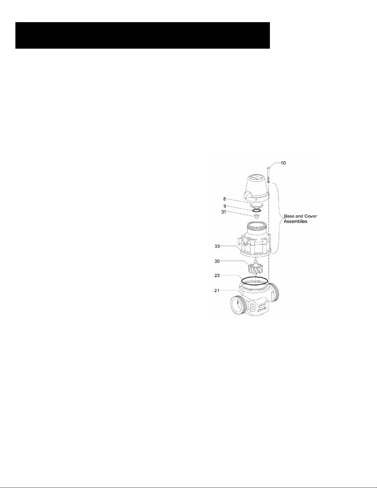
HYDROMETER COVER AND BASE ASSEMBLIES
Removal
• Remove the register assembly as described on page 25.
• Loosen and remove the upper bearing bolt (8) using the specially
sized box wrench. Model number: 03640-000071
• Remove the upper bearing bolt o-ring (9) from the groove in the
underside of the bolt. Inspect and replace as necessary.
• Loosen and remove the six cover screws (10), with the washers.
• Lift the base and cover assemblies off of the hydrometer body (21).
• Be especially careful not to damage the impeller.
• Place the two assemblies upside down. Pull the impeller (30) up
and out.
• Some force may be required to free the impeller.
• Remove the magnet housing (31) from inside the cover assembly.
The magnet housing was freed from the impeller shaft during the
previous step.
• Inspect the impeller and its components for signs of excessive wear
or damage.
• Verify that the impeller shaft is straight. Replace as necessary.
Re-assembly
• Carefully place the base and cover assemblies over the impeller shaft
(30).
• Push the magnet housing (31) down over the top of the impeller shaft (which extends
through the hole in the cover). Tap the magnet housing with a hammer to ensure that it
is properly secured to
the shaft.
• Place the base and cover assemblies onto the hydrometer body (21).
• Replace and tighten the six cover screws (10).
• Place the upper bearing bolt o-ring (9) into the groove on the underside of the bolt (8).
• Screw in the upper bearing bolt “O” (8) using the specially sized
box wrench.
• Replace the register assembly and cover as described on page 25.
26 • Hydrometers Operation and Maintenance Manual
Page 27
Maintenance 1½” and 2” Models, Cont.
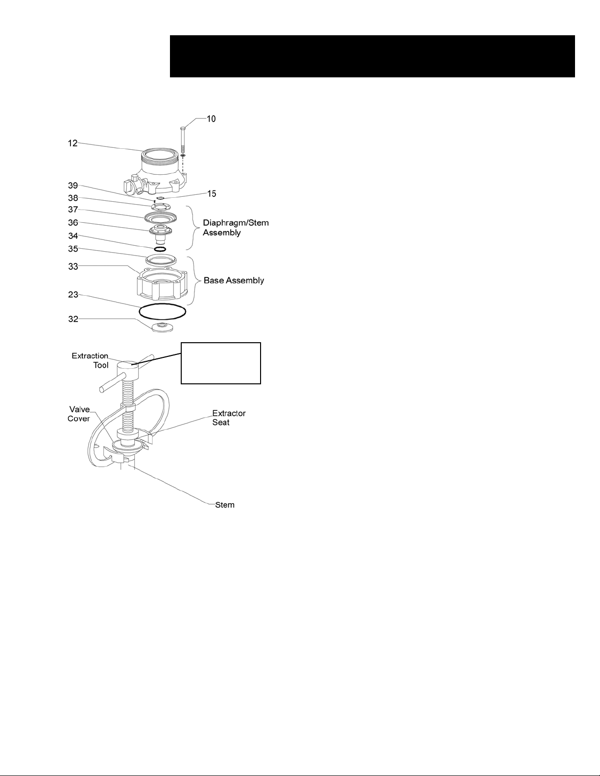
DIAPHRAGM/STEM DIS-ASSEMBLY
• Separate the base assembly from the cover (12).
• Visually inspect the diaphragm (37), valve cover (32) and stem
assembly (36) for damage or excessive wear. If replacement is
needed, continue with the following steps.
• Remove the six screws (39) from the diaphragm retaining ring (38).
• Lift the ring off of the diaphragm (37).
• Lift the diaphragm (37) off of the stem (36).
BASE AND STEM DIS-ASSEMBLY
• Place the base and stem assemblies upside down on a at surface.
• Use the extraction tool to remove the valve cover (32) as follows:
- Slide the lower prongs of the extraction tool under the cover.
- Turn the bolt on the extraction tool clockwise until the
extractor seat ts securely into the stem.
- Continue turning the bolt until the valve cover slides off
of the stem (36).
• Invert the base and pull the stem (36) out of the base (33).
• Remove the base o-ring (23) from the underside of the base. Inspect
and replace as necessary.
Extraction Tool
Model Number:
00360-000072
• Remove the stem o-ring (34) from the groove in the hole in the
center of the base. Inspect and replace as necessary.
• Remove the diaphragm support ring (35) from the base (33).
• Inspect the base (33) for cracks or excessive wear. Replace as
necessary.
WARNING
You must use the extraction tool to remove the valve cover. Use
of any other tool may damage the valve cover and the stem.
Re-assembly
• Insert the diaphragm (37) into the grooves on the top of the stem
(36).
• Place the diaphragm retaining ring (38) over the diaphragm. Secure
the ring with the six screws (39). Apply Loctite 270 or similar glue
to the screws.
• Set the lower diaphragm support ring (35) inside the base (33).
• Insert the re-assembled diaphragm and stem assembly into the base.
• Push the valve cover (32) up onto the bottom of the diaphragm/stem
subassembly. It should easily snap into place.
• Remove and replace the central bushing o-ring (15) at the bottom of
the central bushing (14 not shown), located in the underside of the
cover (12).
• Set the cover (12) onto the re-assembled base subassembly. These
subassemblies are now ready for reinstallation onto the hydrometer
body.
Hydrometers Operation and Maintenance Manual • 27
Page 28

Maintenance 1½” and 2” Models, Cont.
INLET SPIDER AND STRAINER
Dis-assembly
• Loosen the impeller bushing (29) located atop the inlet
spider screw (24) and bushing (28). Pull the entire inlet
spider screw assembly up and out.
• Pull the inlet spider (27) upward and remove it from the
hydrometer body (21). Inspect for cracks or excessive
wear and replace as necessary.
• Remove and replace the body o-ring (26).
• Remove the strainer (25). Clean and inspect for damage or
excessive wear.
• Replace as necessary.
Re-assembly
• Place the body o-ring (26) in the small ange inside the
hydrometer base.
• Place the strainer (25) into the hydrometer base.
• Insert the inlet spider into the body so that the end rests on
the top of the strainer and the ange rests over the body
o-ring (26).
• Place the inlet spider screw assembly through the holes
in the input spider (27) and strainer (25). Use a socket
wrench to tighten the impeller bushing (29) atop the
assembly.
28 • Hydrometers Operation and Maintenance Manual
Page 29
Maintenance 3” and 4” Models
HYDROMETER DIS-ASSEMBLY AND REASSEMBLY
Dis-assembly of the 3” and 4” hydrometer is divided into the following
assemblies:
• Cover Assembly
• Diaphragm/Stem and Base Assemblies
• Inlet Spider/Strainer Assembly
Perform only those steps necessary to inspect and replace parts as directed
by the troubleshooting procedures. It is recommended to replace the
various
o-rings and gaskets during dis-assembly as well as to inspect certain
other parts. All gaskets and o-rings must be covered with grease prior to
installation.
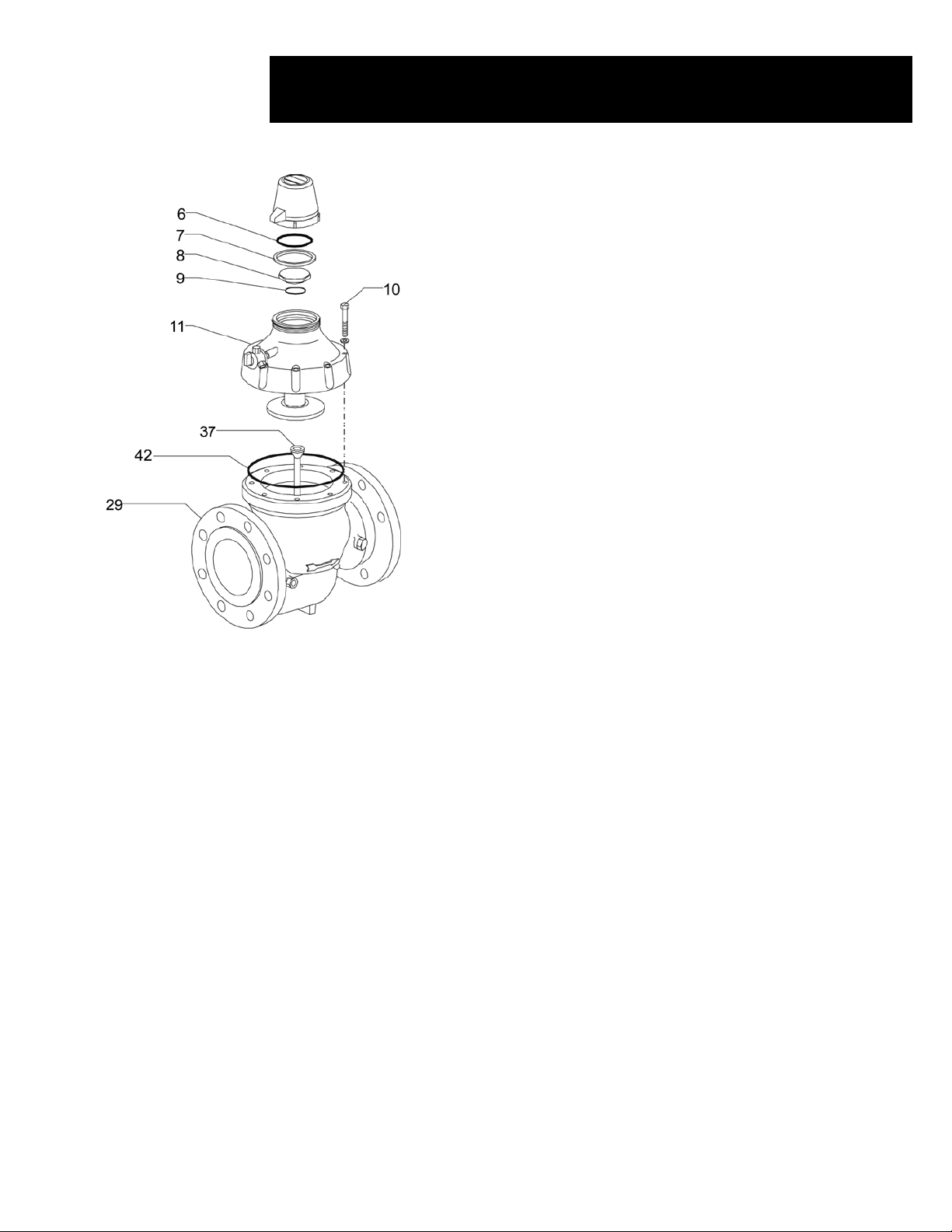
HYDROMETER COVER AND BASE SUBASSEMBLIES
Removal
• Remove the register subassembly as described on page 24.
• Loosen and remove the cover screws (10) along with the washers.
• Lift the cover off of the hydrometer body (29). Be especially careful
not to damage the impeller.
• Carefully remove the impeller assembly (37) from the hydrometer
body.
• Inspect the impeller and its components for signs of excessive wear
or damage. Verify that the impeller shaft is straight. Replace as
necessary.
• Inspect the base o-ring (42) for excessive wear or damage. Replace as
necessary.
Re-assembly
• Insert the impeller (37) into the inlet spider (located inside the
hydrometer base).
• Insert the base “O” ring (42) into the groove on the upper body ange.
• Carefully place the cover over the impeller shaft (37) and onto the
hydrometer body (29).
• Replace and tighten the cover screws (10).
• Replace the register subassembly as described on page 24.
Hydrometers Operation and Maintenance Manual • 29
Page 30
Maintenance 3” and 4” Models, Cont.
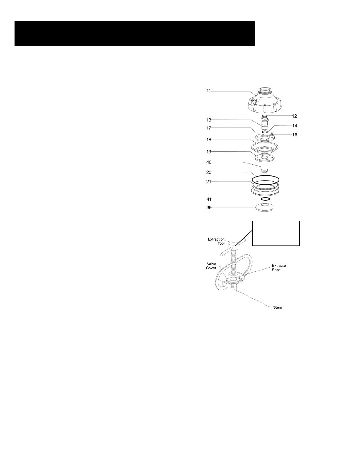
DIAPHRAGM/STEM ASSEMBLY
AND BASE ASSEMBLY
Diaphragm/Stem Dis-assembly
• Pull the diaphragm and stem assemblies up and out from the
hydrometer cover (11). The central bushing (13) remains attached
to the cover.
• Unscrew and remove the central bushing (13) from the cover (11).
• Inspect the upper and lower central bushing o-rings (12,14).
Replace as necessary.
• Visually inspect the diaphragm (18), valve cover (39) and stem
(40) for damage or excessive wear. If repair or replacement is
required, continue with the following steps.
Diaphragm and Base Dis-assembly
• Remove the six screws (16) from the upper diaphragm ring (17).
Lift the upper diaphragm ring off of the diaphragm (18).
• Lift the diaphragm off of the lower diaphragm support ring (19)
and the stem (40). The stem remains attached to lower diaphragm
support ring.
• Place the stem subassembly upside down on a at surface.
• Use the extraction tool to remove the valve cover (32) as follows:
- Slide the lower prongs of the extraction tool under the
valve cover.
- Turn the bolt on the extraction tool clockwise until the
extractor seat ts securely into the stem.
- Continue turning the bolt until the valve cover slides
off of the stem.
• Visually inspect the base o-ring (20) and replace as necessary.
• Visually inspect the stem o-ring (41), located in the groove in the
hole in the center of the base. Replace as necessary.
• Inspect the base (21) for cracks or excessive wear. If replacement
is necessary, pull the base off of the stem. Push the replacement
base onto the stem as far as it can go.
Extraction Tool
Model Number:
00360-000072
WARNING
You must use the extraction tool to remove the valve cover
(39). Use of any other tool may damage the valve cover and
the stem assembly.
Re-assembly
• Insert the diaphragm (18) into the grooves on lower diaphragm support ring (19).
• Place the upper diaphragm ring (17) over the diaphragm. Secure it to the lower diaphragm ring (19)
with the six screws (16). Apply Loctite 270 or similar glue to the screws.
• Push the base up onto the stem as far as it will go.
• Push the valve cover (39) up onto the bottom of the stem. It should easily snap into place.
• Insert the re-assembled diaphragm, stem base assemblies into the cover (11).
• Replace the impeller assembly into the inlet spider, located inside the hydrometer body.
30 • Hydrometers Operation and Maintenance Manual
Page 31
Maintenance 3” and 4” Models, Cont.
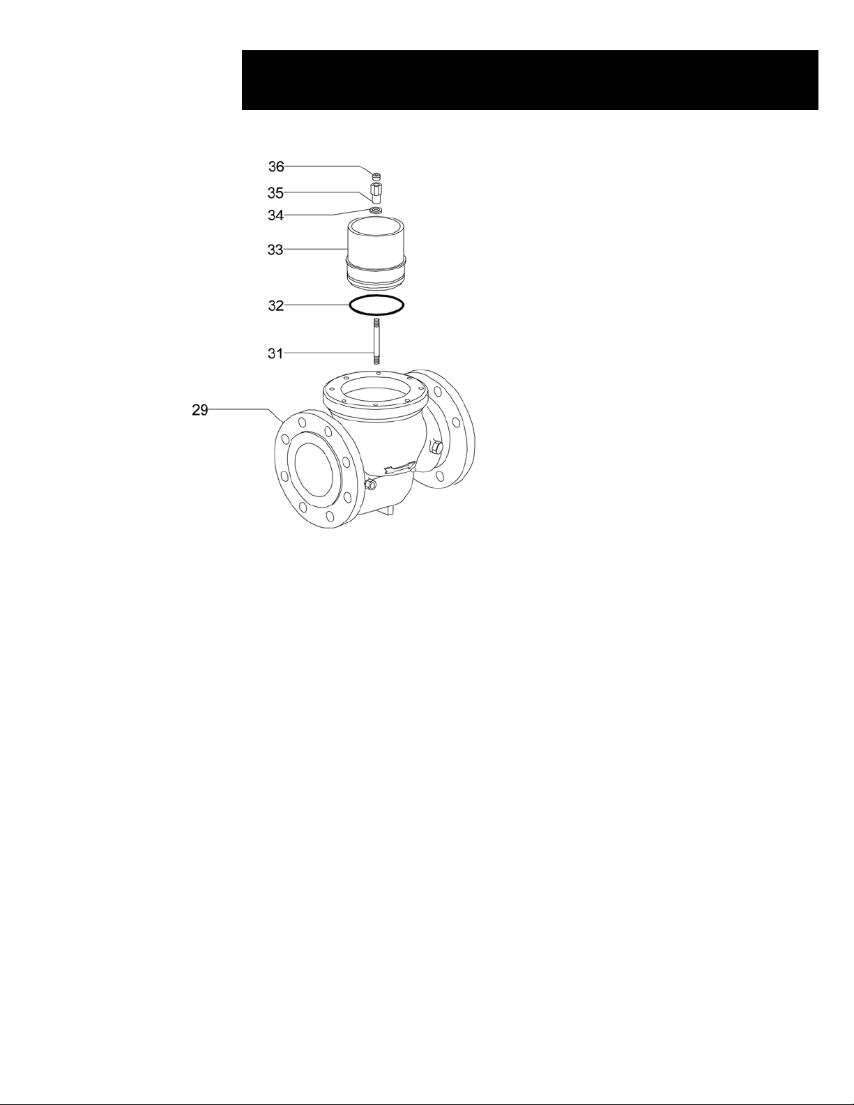
INLET SPIDER AND STRAINER
Dis-assembly
• Loosen and remove the impeller bushing (36), the inlet
spider bearing nut (35) and the inlet spider bearing
washer (34).
• Remove the inlet spider tube (33).
• Inspect the inlet spider o-ring (32) and replace as
necessary.
Re-assembly
• Replace the inlet spider tube (33)
• Replace the inlet spider bearing washer (34) and nut
(35) onto the inlet spider shaft (31) and tighten.
• Replace the impeller bushing (36) into the inlet spider
nut (35).
Hydrometers Operation and Maintenance Manual • 31
Page 32
Maintenance 6” Models
HYDROMETER DIS-ASSEMBLY AND REINSTALLATION
The dis-assembly of the 6” hydrometer is divided into the following
subassemblies:
• Register
• Hydrometer Cover
• Diaphragm and Stem Assemblies
• Stem and Valve Seal Assemblies
• Impeller and Flow Tube Assemblies
• Inlet Spider Assembly
Perform only those procedures necessary to inspect and replace parts as
directed by the troubleshooting procedures. It is recommended to replace the
various o-rings and gaskets during dis-assembly as well as to inspect certain
other parts. All gaskets and o-rings must be covered with grease prior to
installation.
REGISTER
Dis-assembly
• Remove the register assembly as detailed on page 24.
• Using a large box wrench, unscrew and remove the upper bearing bolt (8).
Use spacing tool, Model number 00360-000072.
• Inspect the upper bearing o-ring (9). Replace as necessary.
• Using a screwdriver or a special key, loosen the guide tube nut (10). It is
not necessary to remove the nut.
Re-assembly
• Tighten the guide tube nut (10). Use spacing tool, Model number
00360-000072.
• Screw the upper bearing bolt (8) back into the cover.
• Replace the register assembly.
HYDROMETER COVER
Disassembly
• Loosen and remove the six cover hex bolts (46) along with their nuts (32)
and washers (33).
• Remove the spring (16).
• Lift out the guide tube (23).
• Inspect and replace as necessary.
• Pull the diaphragm/stem assembly out of the hydrometer body. Be careful
not to damage the impeller during removal.
Re-assembly
• Carefully replace the diaphragm/stem assembly over the impeller shaft and
into the hydrometer body. Be careful not to damage the impeller.
• Place the guide tube (23) over the impeller shaft.
• Place the spring (16) over the guide tube (23).
• Replace the hex cover bolts (46) together with their washers and nuts.
32 • Hydrometers Operation and Maintenance Manual
Page 33

Maintenance 6” Models, Cont.
DIAPHRAGM AND UPPER STEM BEARING
Dis-assembly
• Unscrew and remove the 12 screws (17) and remove the upper
diaphragm ring (18).
• Remove the diaphragm (19).
• Inspect for cracks or excessive wear and replace as necessary.
• Inspect the upper stem wiper (20) and replace as necessary.
• Remove the upper stem bearing (21) from inside the stem
(24). Inspect the upper stem bearing (21) along with the upper
stem bearing o-ring (22) and the stem o-ring (15). Replace as
necessary.
Re-assembly
• Replace the upper stem wiper (20) onto the upper stem bearing
(21)
• Replace the upper stem bearing (21) into the stem (24).
• Place the diaphragm (19) into the grooves on the stem (24).
• Place the upper diaphragm ring (18) over the diaphragm and
screw the 12 stem screws (17) into place.
LOWER STEM BEARING AND VALVE COVER
Dis-assembly
• Unscrew and remove the stem lock nut (29).
• Pull the valve cover (28) from the stem. Inspect the rubber for
cracks or excessive wear. Replace as necessary.
• Inspect the lower valve cover o-ring (26) and replace as
necessary. It is located in a groove inside the valve cover
opening.
• Using a screwdriver, remove the lock ring (27) from inside the
bottom of the stem (24).
• Inspect the lower stem bearing wiper (20) and the lower stem
bearing o-ring (22) and replace as necessary.
• Inspect and replace the lower stem bearing (25) as necessary.
Use a pipe wrench to remove it from the stem (24).
• Apply Loctite 270 or similar glue to the threads of the lower
stem bearing (25).
• Screw it back into the stem (24).
Re-assembly
• Replace the lower stem wiper (20) into the bottom of the stem
(24).
• Snap the wiper locking ring (27) into the stem (24).
• Push the valve cover (28) onto the lower stem bearing (25).
• Apply Loctite 270 or similar glue to the threads of the stem
lock nut (29).
• Screw the stem lock nut (29) into the stem (24). Do not over
tighten. Make sure that the valve cover is free to move up and
down slightly.
Hydrometers Operation and Maintenance Manual • 33
Page 34

Maintenance 6” Models, Cont.
IMPELLAR AND FLOW TUBE SUB-ASSEMBLIES
Dis-assembly
• Remove valve seat base (45) from atop the ow tube (41). Be careful not
to damage the impeller shaft. Inspect for excessive wear and replace as
necessary.
• Remove the impeller assembly (43). Inspect for cracks or excessive
wear and check that the impeller shaft is perfectly straight. Replace if
necessary.
• Remove the ow tube (41).
• Inspect and replace as necessary.
• Inspect the upper and lower ow tube o-rings (40) and replace as
necessary.
• Remove the inlet spider assembly (38). Inspect and repair as necessary.
Re-assembly
• Replace the inlet spider assembly (38) into the hydrometer body.
• Place the lower ow tube o-ring (40) onto the ow tube (41).
• Place the upper ow tube o-ring into the valve seat base (45).
• Replace the ow tube (41) atop the inlet spider assembly (38) in the
hydrometer body.
• Replace the impeller assembly (43) into the ow tube (41) so that the
impeller shaft rests in the lower bearing bushing (39).
• Place the valve seat base (45) over the impeller shaft so that it rests atop
the ow tube (41).
INLET SPIDER
Dis-assembly
• Unscrew and remove the cap (35). Inspect and replace as necessary.
• Remove the lock nut (36).
• Unscrew and remove the lower bearing screw (37) from the inlet spider
(38). Inspect and replace as necessary.
• Inspect the inlet spider (38) and the lower bearing bushing (39) and
replace as necessary.
Re-assembly
• Screw the lower bearing bushing (37) back into the inlet spider (38).
• Replace the lower bearing screw (37) into bottom of the inlet spider.
Tighten approximately eight turns.
• Replace the lock nut (36) and the spider cap (35).
34 • Hydrometers Operation and Maintenance Manual
Page 35
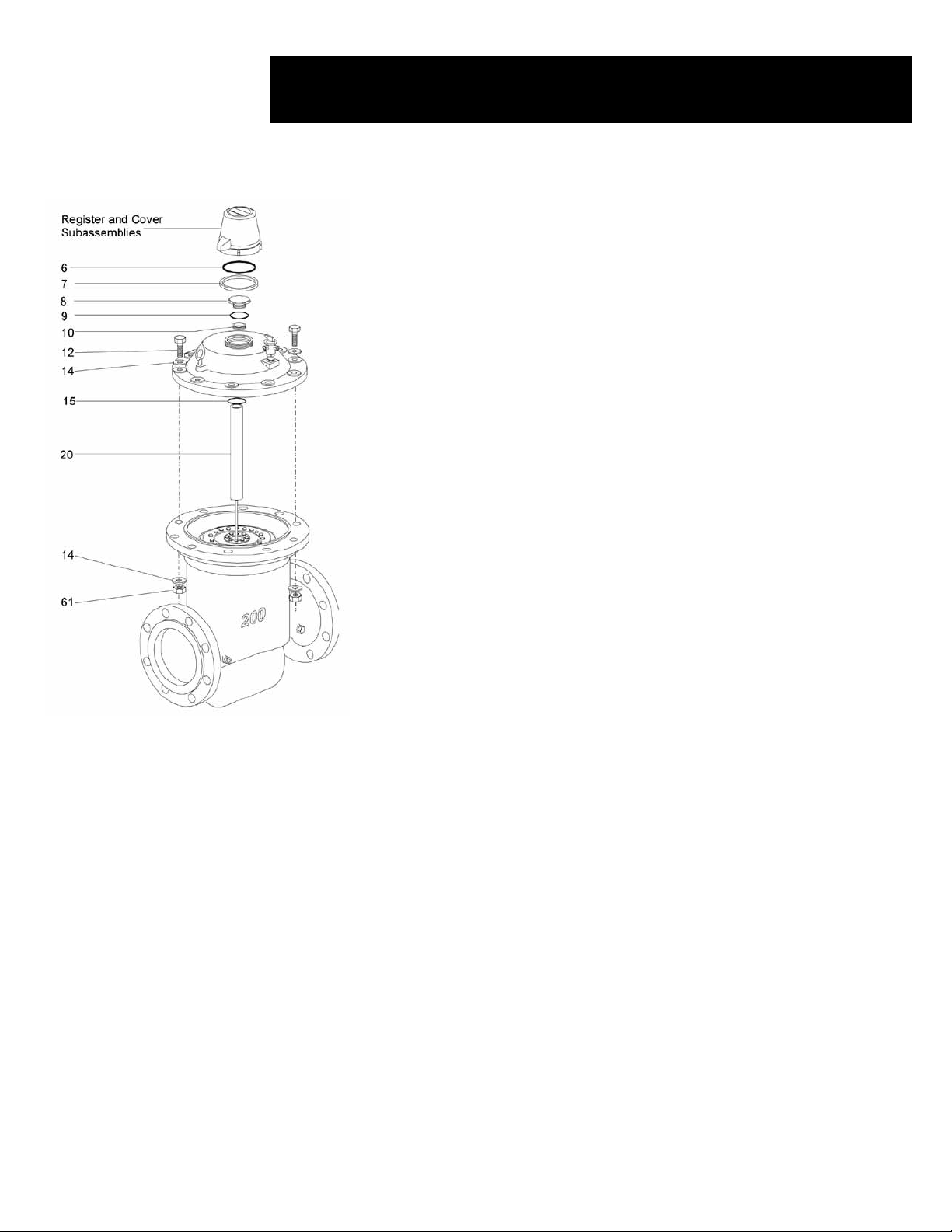
Maintenance 8” Models
HYDROMETER DIS-ASSEMBLY AND RE-ASSEMBLY
The dis-assembly of the 8” hydrometer is divided into the following logical assemblies:
• Register
• Hydrometer Cover
• Diaphragm Sub-assembly
• Lower Chamber Disc Sub-assembly
• Stem and Valve Cover Sub-assemblies
• Impeller and Flow Tube Assemblies
• Inlet Spider Assembly
Perform only those procedures necessary to inspect and replace parts as directed by the
troubleshooting procedures. It is recommended to replace the various o-rings and gaskets
during dis-assembly as well as to inspect certain other parts. All gaskets and o-rings must be
covered with grease prior to installation.
REGISTER
Dis-assembly
• Remove the register assembly as detailed on page 24.
• Using a large box wrench, loosen and remove the upper bearing bolt (8).
• Remove upper bearing o-ring (9). Inspect and replace as necessary.
• Using a screwdriver or a special key, loosen the guide tube nut (10). It is not necessary to
remove the nut.
Re-assembly
• Re-tighten the guide tube nut (10).
• Replace the upper bearing o-ring (9).
• Replace and tighten the upper bearing bolt (8).
• Replace the register assembly.
HYDROMETER COVER
Disassembly
• Loosen and remove the cover hex bolts (12) along with their nuts (61) and washers (14).
• Attach a hoist cable or chain to the rings on the hydrometer cover (14). Use the hoist to
lift the cover off of the hydrometer body. Be careful not to damage the impeller shaft.
• Lift out the guide tube (20).
• Inspect and replace as necessary.
• Inspect the cover o-ring (15) and replace as necessary. The o-ring is located on the
underside of the cover in the upper opening.
Re-assembly
• Replace the guide tube (20) over the impeller shaft.
• Replace the hydrometer cover (24) onto the body.
• Replace the cover hex bolts (12) along with their washers (14) and nuts (61).
• Tighten the nuts.
DIAPHRAGM SUB-ASSEMBLY
Removal of Diaphragm Assembly
• Remove all eight screws from the inner circle of screws on the lower diaphragm disc
(25). Four of the screws are ½” length (21) and four are 7∕8” length (24).
• Insert the four 7∕8” screws (24) into the holes from which you removed the four ½”
(21) screws and tighten. This will lift the entire diaphragm subassembly off of the stem
subassembly.
• Pull the diaphragm subassembly up and remove it from the hydrometer body.
• Inspect the diaphragm (23) for cracks or excessive wear. Continue with the following
steps to replace the diaphragm only if necessary.
Hydrometers Operation and Maintenance Manual • 35
Page 36

Maintenance 8” Model, Cont.
DIAPHRAGM SUB-ASSEMBLY DIS-ASSEMBLY
Dis-assembly and Re-assembly
• Remove the sixteen ½” screws (21) from the upper diaphragm ring (22).
• Lift the upper diaphragm ring (22) off of the diaphragm (23).
• Lift the diaphragm (23) off of the lower diaphragm disc (25).
• Place the replacement diaphragm (23) onto the lower diaphragm disc (25).
• Place the upper diaphragm ring (22) over the diaphragm.
• Replace and tighten the ½” screws (21) into the upper diaphragm ring.
Replacement in the Body
Perform the preceding steps in the reverse order to reassemble the diaphragm
assembly.
1. Replace and tighten the four ½” screws (21) and the four 7∕8” screws (24)
into the lower diaphragm disc (25).
2. Place the diaphragm assembly over the impeller shaft onto the lower
chamber disc and stem assemblies.
LOWER CHAMBER DISC SUB-ASSEMBLY
Dis-assembly
The following steps are performed following removal of the diaphragm
sub-assembly as described on page 24.
• Remove the six 6 mm screws (33) from the top of the lower chamber disc (27).
• Remove the two lower chamber disc locking rings (26).
• Temporarily replace the diaphragm subassembly onto the lower chamber
disc (27).
• Insert and tighten the four 7∕8” screws (24) into the lower diaphragm disc
(innermost ring) on the diaphragm subassembly, temporarily re-attaching
it to the stem.
• Pull upward and lift to remove the diaphragm subassembly, together with
the lower chamber disc and stem subassemblies, from the hydrometer body.
• Remove, once again, the four 7∕8” screws (24) and pull the diaphragm
subassembly up from the stem.
• Lift the lower chamber disc (27) off of the stem (41).
• Inspect the two lower chamber o-rings (28) and (29) on outside of the
lower chamber disc (27). Replace as necessary.
• Remove the four ½” screws (21) that fasten the lower chamber ring (35)
to bottom of the lower chamber disc (27) and remove the lower chamber
ring.
• Inspect the lower chamber bearing wiper (32). Replace as necessary.
• Remove the lower chamber bearing (30) from inside the lower chamber
disc (27). Inspect and replace as necessary.
• Inspect the lower chamber bearing o-rings (31 and 34). Replace as
necessary.
Re-assembly
• Replace the lower chamber bearing (30) into the lower chamber disc.
• Replace the lower chamber bearing ring (35) onto the lower chamber
disc.
• Insert and tighten the four ½” screws (21).
• Perform the rest of the above steps in the reverse order.
36 • Hydrometers Operation and Maintenance Manual
Page 37

Maintenance 8” Model, Cont.
STEM SUB-ASSEMBLY AND VALVE COVER
Follow this procedure only if it is necessary to replace the stem
bearings or the valve cover. Otherwise, skip this section:
Dis-assembly and Re-assembly
• Inspect the upper stem bearing wiper (36). Replace as necessary.
• Remove the upper stem bearing (37) from the stem (41).
• Inspect the upper stem bearing o-rings (38,39). Replace as
necessary.
• Unscrew and remove the stem locking nut (48), located at the
bottom of the stem subassembly.
• Remove the valve cover (47) from the stem. Inspect the rubber for
cracks and excessive wear. Replace as necessary.
• Inspect the valve cover o-ring (43) and replace as necessary.
• Remove the retaining ring (46) that holds the lower stem bearing
wiper (45) in place. Inspect the lower stem bearing wiper (45) and
replace as necessary.
• Inspect the lower stem bearing o-ring (44) and replace as
necessary.
• Inspect the lower stem bearing (42) for scratches or wear. Replace
as necessary.
• Apply Loctite 270 or similar glue to the threads of the lower stem
bearing and screw it into the stem assembly (41).
• Replace the valve cover (47) onto the stem assembly.
• Apply Loctite 270 or similar glue to the threads of the stem
locking nut (48) and screw into the stem assembly.
• Push the upper stem bearing (37) onto the stem assembly.
Hydrometers Operation and Maintenance Manual • 37
Page 38

Maintenance 8” Models, Cont.
IMPELLAR AND FLOW TUBE ASSEMBLIES
Dis-assembly
• Remove valve seat base (49) from atop the ow tube (55). Be careful not
to damage the impeller shaft. Inspect the valve seat base for excessive
wear and replace as necessary.
• Remove the impeller (50).
• Inspect for cracks or excessive wear and check that the impeller shaft is
perfectly straight. Replace if necessary.
• Remove the ow tube (55).
• Inspect and replace as necessary.
• Inspect the upper and lower ow tube o-rings (54) and replace as
necessary.
• Remove the inlet spider (57) assembly. Inspect and repair as necessary.
Re-assembly
• Replace the inlet spider assembly (57) into the hydrometer body.
• Place the two lower ow tube o-rings (54) onto the ow tube (55).
• Place the upper ow tube o-ring (54) into the valve seat base (49).
• Replace the ow tube (55) atop the inlet spider assembly (57) in the
hydrometer body.
• Replace the impeller assembly (51) into the ow tube (55) - the impeller
shaft should rest in the lower bearing bushing (56).
• Place the valve seat base (49) over the impeller shaft so that it rests atop
the ow tube (55).
INLET SPIDER
Dis-assembly
• Unscrew and remove the cap (60). Inspect and replace as necessary.
• Remove the lock nut (59).
• Unscrew and remove the lower bearing screw (58) from the inlet spider
(57). Inspect and replace as necessary
• Inspect the inlet spider (57) and the lower bearing bushing (56) and
replace as necessary.
Re-assembly
• Screw the upper bearing bushing (56) back into the top of the inlet
spider (57).
• Replace the lower bearing screw (58) into bottom of the inlet spider.
Tighten approximately eight turns.
• Replace the lock nut (59) and the cap (60).
38 • Hydrometers Operation and Maintenance Manual
Page 39

Schematics
SCHEMATICS TABLE OF CONTENTS
Manual Electric
1½”, 2” Hydrometer, Manual Electric Normally Closed, 8mm Tubing .................................. 40
1½”, 2” Hydrometer, Manual Electric Normally Open, 8mm Tubing ..................................... 41
3”, 4” Hydrometer, Manual Electric Normally Closed, 8mm Tubing ..................................... 42
3”, 4” Hydrometer, Manual Electric Normally Open, 8mm Tubing ........................................ 43
6”, 8” Hydrometer, Manual Electric Normally Closed, 8mm Tubing ..................................... 44
6”, 8” Hydrometer, Manual Electric Normally Open, 8mm Tubing ....................................... 45
Pressure Reducing, Manual Electric
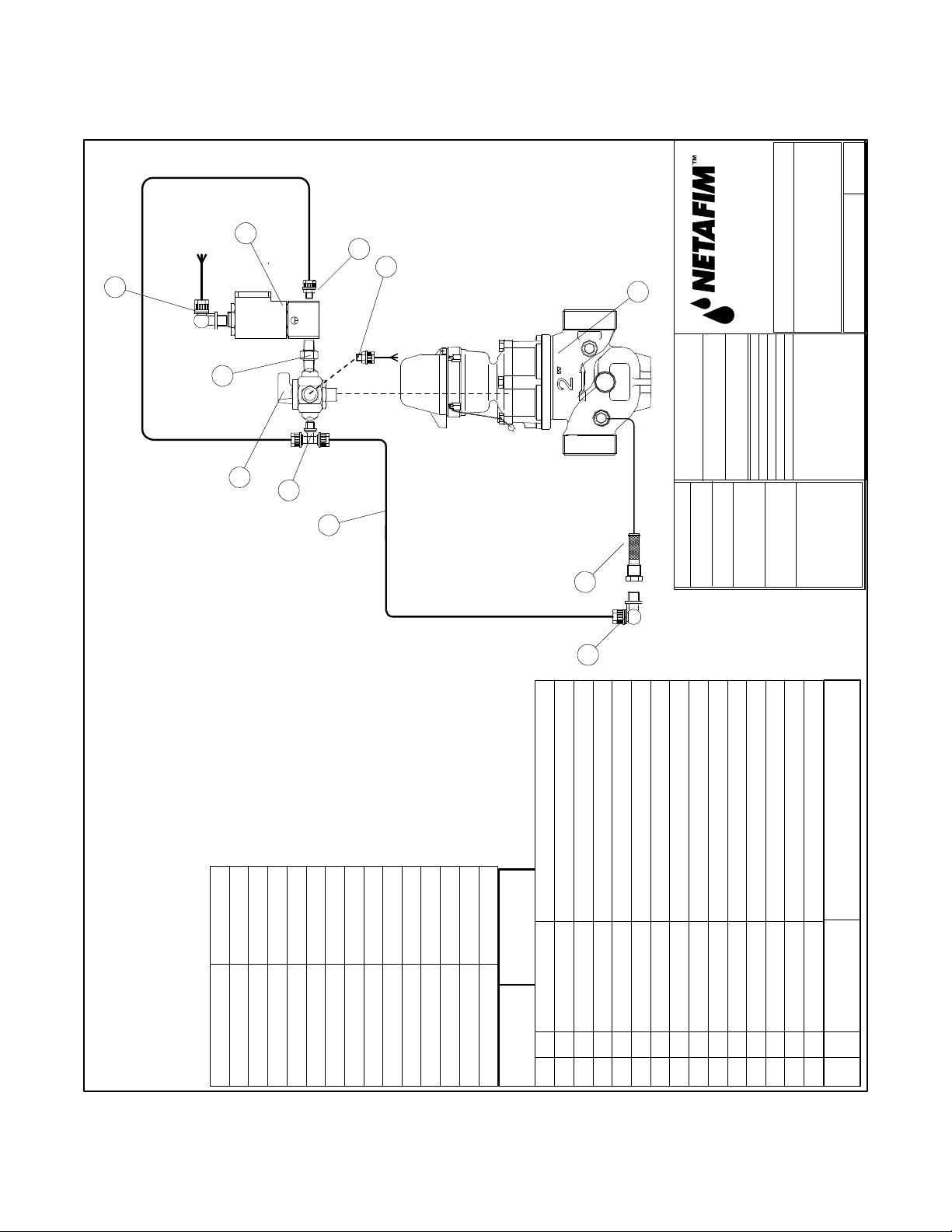
1½”, 2” Hydrometer, Pressure Reducing Manual Electric Normally Closed, 8mm Tubing ... 46
1½”, 2” Hydrometer, Pressure Reducing Manual Electric Normally Open, 8mm Tubing ...... 47
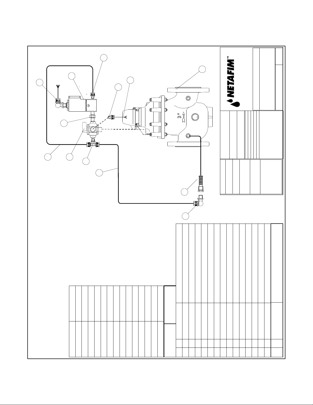
3”, 4” Hydrometer, Pressure Reducing Manual Electric Normally Closed, 8mm Tubing ...... 48
3”, 4” Hydrometer, Pressure Reducing Manual Electric Normally Open, 8mm Tubing ......... 49
6”, 8” Hydrometer, Pressure Reducing Manual Electric Normally Closed, 8mm Tubing ...... 50
6”, 8” Hydrometer, Pressure Reducing Manual Electric Normally Open, 8mm Tubing ......... 51
Hydrometers Operation and Maintenance Manual • 39
Page 40

1½”, 2” HYDROMETER, MANUAL ELECTRIC, NORMALLY CLOSED, 8MM TUBING
0
rev
3
5
2 1
2
AUTO
CLOSED
7
7
1
5470 E Home Ave.
Fresno, CA 93727
T (888) 638-2346
F (800) 695-4753
N
E
P
O
Approved: P C
8MM PE TUB ING
1.5", 2" Hydrometer
MANUAL ELECTRIC NC
Part Number: LHMxxTG- MEL-NC
4
6
Material: ASTM 102 0
prepared by PC
Date: 9-6-08
8
9
Scale: 1=1
Units: English [metri c]
Quantity: 1
Surface Finish: N/A
Heat Treatment: N /A
Tolerances:
5
LHM1.5TG-MEL-NC
LHM2TG-MEL-NC
40 • Hydrometers Operation and Maintenance Manual
Basic Hydrometer 1.5 and 2 "
BRASS HEX NIPPLE 1/8"
SOLENOID 3-WAY 24VAC N.O.
LHMxxTG
55B216P2
1111212
Part No. Part No.
Variable Finished Goods
1234567
noitpircseDtnenopmoCYTQmetI
3-WAY VALVE 1/8" X 1/ 8"
Plastic male 90-Elbow 8mm x 1 /8" npt
Plastic male branch tee 8mm x 1 /8" npt
Plastic male connector 8mm x 1 /8" npt
PE TUBING 8MM
BRASS FINGER FILTER 1/4" X 1/8 "
Part No.
36SOLNO-024
62SV21/8M
55P4694802
55P4724802
55P4684802
15CONT-8-I
61SF25SB
2
1
8
9
1011121314
15
Page 41
1½”, 2” HYDROMETER, MANUAL ELECTRIC, NORMALLY OPEN, 8MM TUBING
0
rev
3
7
7
5470 E Home Ave.
Fresno, CA 93727
T (888) 638-2346
5
1
2 1
N
E
P
O
2
AUTO
CLOSED
Material: ASTM 102 0
4
prepared by PC
F (800) 695-4753
Approved: P C
Date: 9-6-08
8MM PE TUB ING
1.5", 2" Hydrometer
MANUAL ELECTRIC NO
Part Number: LHMxxTG -MEL-N O
6
8
Scale: 1=1
Units: English [metri c]
Quantity: 1
Surface Finish: N/A
Heat Treatment: N /A
9
Tolerances:
5
noitpircseDtnenopmoCYTQmetI
Basic Hydrometer 1.5 and 2 "
BRASS HEX NIPPLE 1/8"
SOLENOID 3-WAY 24VAC N.C.
3-WAY VALVE 1/8" X 1/ 8"
Plastic male 90-Elbow 8mm x 1 /8" npt
Plastic male branch tee 8mm x 1 /8" npt
Plastic male connector 8mm x 1 /8" npt
PE TUBING 8MM
BRASS FINGER FILTER 1/4" X 1/8 "
Part No.
LHMxxTG
55B216P2
36SOLNC-024
62SV21/8M
55P4694802
55P4724802
55P4684802
15CONT-8-I
61SF25SB
111
Part No. Part No.
Variable Finished Goods
LHM1.5TG-MEL-N O
LHM2TG-MEL-N O
123
12122
45678
1
9
1011121314
15
Hydrometers Operation and Maintenance Manual • 41
Page 42

3”, 4” HYDROMETER, MANUAL ELECTRIC, NORMALLY CLOSED, 8MM TUBING
7
0
rev
1
3
5
2 1
N
E
P
O
2
8
AUTO
CLOSED
4
6
8
7
5470 E Home Ave.
Fresno, CA 93727
T (888) 638-2346
F (800) 695-4753
Material: ASTM 102 0
Date: 9-6-08
prepared by PC
8mm tubin g
3",4" Hydrometer
MANUAL ELECTRIC NC
Approved: Perry Contine nte
Part Number: LHMxFG- MEL-NC
8
9
Scale: 1=1
Units: English [metri c]
Quantity: 1
Surface Finish: N/A
Heat Treatment: N /A
Tolerances:
5
noitpircseDtnenopmoCYTQmetI
SOLENOID 3-WAY 24VAC N.O.
Basic Hydrometer 3",4"
LHMxFG
111121221
Part No. Part No.
Variable Finished Goods
LHM3FG-MEL-NC
LHM4FG-MEL-NC
123456789
3-WAY VALVE 1/8" X 1/8" MAL E
BRASS HEX NIPPLE 1/8"
PLASTIC MALE 90-ELBOW 8MM X 1/8"
PLASTIC MALE BRANCH-TEE 8MM X 1/8"
PLASTIC MALE CONNECTOR 8MM X 1/8"
PE TUBING 8MM
BRASS FINGER FILTER 1/4" X 1/8 "
Part No.
36SOLNO-024
55B216P2
62SV21/8M
55P4684802
55P4714802
55P4684802
15CONT-8-I
61SF25SB
1011121314
15
42 • Hydrometers Operation and Maintenance Manual
Page 43
3”, 4” HYDROMETER, MANUAL ELECTRIC, NORMALLY OPEN, 8MM TUBING
7
0
rev
1
3
5
2 1
N
E
P
O
2
8
4
AUTO
CLOSED
8
7
5470 E Home Ave.
Fresno, CA 93727
T (888) 638-2346
F (800) 695-4753
Material: ASTM 102 0
prepared by PC
Date: 9-6-08
8mm tubin g
3",4" Hydrometer
MANUAL ELECTRIC NO
Approved: Perry Contine nte
Part Number: LHMxFG -MEL-NO
6
8
Scale: 1=1
Units: English [metri c]
Quantity: 1
Surface Finish: N/A
Heat Treatment: N /A
9
Tolerances:
5
noitpircseDtnenopmoCYTQmetI
Basic Hydrometer 3",4"
BRASS HEX NIPPLE 1/8"
SOLENOID 3-WAY 24VAC N.C.
3-WAY VALVE 1/8" X 1/8" MAL E
PLASTIC MALE 90-ELBOW 8MM X 1/8"
PLASTIC MALE BRANCH-TEE 8MM X 1/8"
PLASTIC MALE CONNECTOR 8MM X 1/8"
PE TUBING 8MM
BRASS FINGER FILTER 1/4" X 1/8 "
Part No.
LHMxFG
55B216P2
36SOLNC-024
62SV21/8M
55P4684802
55P4714802
55P4684802
15CONT-8-I
61SF25SB
111
Part No. Part No.
Variable Finished Goods
LHM3FG-MEL-N O
LHM4FG-MEL-N O
123
12122
45678
1
9
1011121314
15
Hydrometers Operation and Maintenance Manual • 43
Page 44

6”, 8” HYDROMETER, MANUAL ELECTRIC, NORMALLY CLOSED, 8MM TUBING
7
16
3
0
rev
15
12
8
PC
2 1
5470 E Home Ave.
Fresno, CA 93727
T (888) 638-2346
N
E
P
11
O
AUTO
F (800) 695-4753
8MM PE TUB ING
6", 8" Hydrometer MEL - NC
Approved:
Part Number: LHMxFG- MEL-NC
6
11
CLOSED
13
5
14
Engr:
Date: 09/20/08
Material: ASTM 102 0
1
8
2
9
Scale: 1=1
Units: English [metri c]
Quantity: 1
Surface Finish: N/A
Heat Treatment: N /A
Tolerances:
4
6
11
10
LHM6FG-MEL-NC
LHM8FG-MEL-NC
LHM8FG
LHM6FG
44 • Hydrometers Operation and Maintenance Manual
noitpircseDtnenopmoCYTQmetI
BASIC 6" HYDROMETER
IN-LINE FILTER BRS LONG 1/4"
PLASTIC MALE 90-ELBOW 8MM X 1/8"
BALL VALVE BRASS 1/4"
3-WAY VALVE 1/4" X 1/4" MAL E
BRASS STREET TEE 1/4"F X 1/4"M
PLASTIC MALE CONNECTOR 8MM X 1/8"
PLASTIC MALE CONNECTOR 8MM X 1/4"
BRASS ADAPTER 1/4"F X 1/4"M
SHRADER VALVE
BRASS BUSHING 1/4"M X 1/8"F
BRASS HEX NIPPLE 1/8"
BRASS ADAPTER 1/4"F X 1/8"M
61SF25LB
55P4684802
62SBV25
62SV41/4M
55B2225P4
55P4684802
55P4684804
55B222P44
61APS1/8
55B209P42
55B216P2
LHM6FG
111
Part No. Part No.
Variable Finished Goods
123
1111211211121
45678
9
1011121314
55B222P42
SOLENOID 3-WAY 24VAC N.O.
MALE BRANCH TEE 8MM X 1/4" NPT
PE TUBING 8MM
SOLENOID 3-WAY 24VAC N.O. WITH
Part No.
55P4714804
15CONT-8-I
36SOLNO-02416
1
15
171819
Page 45

6”, 8” HYDROMETER, MANUAL ELECTRIC, NORMALLY OPEN, 8MM TUBING
15
7
0
rev
16
3
PC
8
5470 E Home Ave.
Fresno, CA 93727
T (888) 638-2346
2 1
N
E
P
11
O
AUTO
F (800) 695-4753
8MM PE TUB ING
6", 8" Hydrometer MEL- NO
Approved:
Part Number: LHMxFG -MEL-NO
12
6
11
CLOSED
5
14
13
Engr:
Date: 09/20/08
Material: ASTM 102 0
1
8
2
9
Scale: 1=1
Units: English [metri c]
Quantity: 1
Surface Finish: N/A
Heat Treatment: N /A
Tolerances:
4
6
11
10
noitpircseDtnenopmoCYTQmetI
BASIC 6" HYDROMETER
IN-LINE FILTER BRS LONG 1/4"
PLASTIC MALE 90-ELBOW 8MM X 1/8"
BALL VALVE BRASS 1/4"
3-WAY VALVE 1/4" X 1/4" MAL E
BRASS STREET TEE 1/4"F X 1/4"M
PLASTIC MALE CONNECTOR 8MM X 1/8"
PLASTIC MALE CONNECTOR 8MM X 1/4"
BRASS ADAPTER 1/4"F X 1/4"M
SHRADER VALVE
BRASS BUSHING 1/4"M X 1/8"F
BRASS HEX NIPPLE 1/8"
BRASS ADAPTER 1/4"F X 1/8"M
LHM6FG-MEL-NO
LHM8FG-MEL-NO
61SF25LB
55P4684802
62SBV25
62SV41/4M
55B2225P4
55P4684802
55P4684804
55B222P44
61APS1/8
55B209P42
55B216P2
LHM6FG
111
Part No. Part No.
LHM8FG
LHM6FG
Variable Finished Goods
123
111121121
45678
9
1011121314
55B222P42
112
SOLENOID 3-WAY 24VAC N.C.
MALE BRANCH TEE 8MM X 1/4" NPT
PE TUBING 8MM
SOLENOID 3-WAY 24VAC N.O. WITH
Part No.
55P4714804
15CONT-8-I
36SOLNC-02416
1
1
15
171819
Hydrometers Operation and Maintenance Manual • 45
Page 46

1½”, 2” HYDROMETER, PRESSURE REDUCING MANUAL ELECTRIC,
NORMALLY CLOSED, 8MM TUBING
11
8
6
13
9
0
rev
10
8mm tubing
12
12
Close
3
12
14
4
Auto
2
1
1
Material: ASTM 102 0
5470 E Home Ave.
Fresno, CA 93727
Engr:
Date: 4/21/08
T (888) 638-2346
F (800) 695-4753
Approved: P C
Pressure Reducing Electric NC
1.5", 2" HYDRO METER GLOBE,
Part Number: LHMxxTG-PR MEL-NC
2
Scale: 1=1
Units: English [metri c]
Quantity: 1
Surface Finish: N/A
Heat Treatment: N /A
5
15
8
Tolerances:
6
7
noitpircseDtnenopmoCYTQmetI
1.5"'2" HYDRO METER FLANGED GLOBE
BRASS FINGER FILTER
BASIC PLASTIC PRESSURE REDUCING PILOT
3-WAY VALVE 1/8" X 1/8" MAL E
PLASIC MALE 90-ELBOW 8MM X 1/8"
PLASTIC MALE BRANCH-TEE 8M X 1/8"
PE CONTROL TUBE 8MM
PLASTIC MALE CONNECTOR 8MM X 1/8"
BRASS BUSHING 1/4" X 1/8" F
BRASS STREET TEE 1/4" X 1/4"
SHRADER VALVE
PILOT FITTING X 8MM TUBIN G
PLASTIC MALE CONNECTOR 8MM X 1/4"
BRASS HEX NIPPLE 1/8"
SOLENOID 3-WAY 24 VAC N.O.
LHMxxTG-PRMEL
Part No.
61APS1/8
3624235309
55P4684804
55B216P2
LHM1.5,2TG
61SF25SB
36PIL29-117-GRY
62SV21/8M
55P4694802
55P4724802
15CONT-8-I
55P4684802
55B209P42
55B2225T4
111112521113111
Part No. Part No.
Variable Fini shed Goods
LHMxxTG
123456789
1011121314
36SOLNO-024
15
46 • Hydrometers Operation and Maintenance Manual
Page 47

1½”, 2” HYDROMETER, PRESSURE REDUCING MANUAL ELECTRIC,
NORMALLY OPEN, 8MM TUBING
8mm tubing
Pressure Reducing Electric NO
1.5",2" HYDRO METER GLOBE,
Tolerances:
0
rev
Part Number: LHMxxTG-P RMEL-NO
11
6
13
8
12
9
10
5470 E Home Ave.
Fresno, CA 93727
T (888) 638-2346
F (800) 695-4753
12
Approved: PC
Close
3
12
14
4
Auto
2
1
1
Engr:
Date: 4/21/08
Material: AST M 102 0
2
Scale: 1=1
Units: English [metri c]
Quantity: 1
Surface Finish: N/A
Heat Treatment: N/A
15
5
8
6
7
noitpircseDtnenopmoCYTQmetI
1.5"'2" HYDRO METER FLANGED GLOBE
BRASS FINGER FILTER
BASIC PLASTIC PRESSURE REDUCING PILOT
3-WAY VALVE 1/8" X 1/8" MAL E
PLASIC MALE 90-ELBOW 8MM X 1/8"
PLASTIC MALE BRANCH-TEE 8M X 1/8"
PE CONTROL TUBE 8MM
PLASTIC MALE CONNECTOR 8MM X 1/8"
BRASS BUSHING 1/4" X 1/8" F
BRASS STREET TEE 1/4" X 1/4"
SHRADER VALVE
PILOT FITTING X 8MM TUBING
PLASTIC MALE CONNECTOR 8MM X 1/4"
BRASS HEX NIPPLE 1/8"
SOLENOID 3-WAY 24 VAC N.C.
Part No.
LHM1.5,2TG
61SF25SB
36PIL29-117-GRY
62SV21/8M
55P4694802
55P4724802
15CONT-8-I
55P4684802
55B209P42
55B2225T4
61APS1/8
3624235309
55P4684804
55B216P2
36SOLNC-024
111112521113111
Part No. Part No.
Variable Fini shed Goods
LHMxxTG LHMxxTG-PRMEL
123456789
1011121314
15
Hydrometers Operation and Maintenance Manual • 47
Page 48
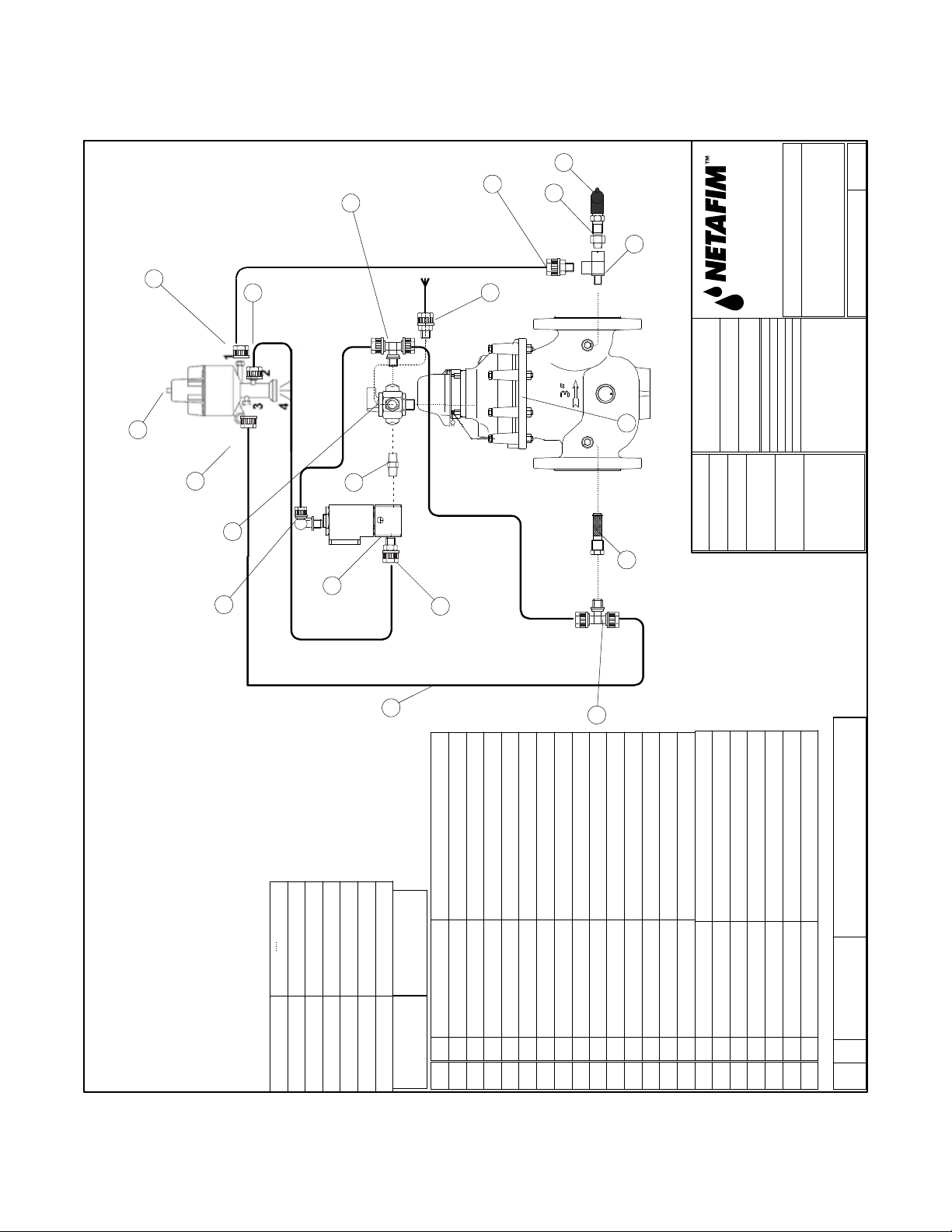
3”, 4” HYDROMETER, PRESSURE REDUCING MANUAL ELECTRIC,
NORMALLY CLOSED, 8MM TUBING
8mm tubing
3",4" HYDRO METER GLOBE,
Pressure Reducing Electric NC
Tolerances:
0
rev
Part Number: LHMxxFG-P RMEL-NC
11
6
13
9
10
5470 E Home Ave.
Fresno, CA 93727
T (888) 638-2346
Engr:
Quantity: 1
F (800) 695-4753
Date: 4/21/08
Surface Finish: N/A
Heat Treatment: N/A
Approved: PC
12
12
Close
3
12
14
4
Auto
2
1
8
1
Material: AST M 102 0
Scale: 1=1
Units: English [metri c]
2
15
5
8
7
3"'4" HYDRO METER FLANGED GLOBE
BRASS FINGER FILTER
BASIC PLASTIC PRESSURE REDUCING PILOT
3-WAY VALVE 1/8" X 1/8" MAL E
PLASIC MALE 90-ELBOW 8MM X 1/8"
PLASTIC MALE BRANCH-TEE 8M X 1/8"
PE CONTROL TUBE 8MM
LHM3FG-PRMEL
LHM4FG-PRMEL
LHM3,4FG
61SF25SB
36PIL29-117-GRY
62SV21/8M
55P4694802
55P4724802
15CONT-8-I
111112521113111
Part No. Part No.
Variable Fini shed G oods
LHM3FG
LHM4FG
123456789
6
PLASTIC MALE CONNECTOR 8MM X 1/8"
BRASS BUSHING 1/4" X 1/8" F
BRASS STREET TEE 1/4" X 1/4"
SHRADER VALVE
55P4684802
61APS1/8
55B209P42
55B2225T4
1011121314
PILOT FITTING X 8MM TUBING
PLASTIC MALE CONNECTOR 8MM X 1/4"
BRASS HEX NIPPLE 1/8"
SOLENOID 3-WAY 24 VAC N.O.
3624235309
55P4684804
55B216P2
noitpircseDtnenopmoCYTQmetI
Part No.
36SOLNO-024
15
48 • Hydrometers Operation and Maintenance Manual
Page 49

3”, 4” HYDROMETER, PRESSURE REDUCING MANUAL ELECTRIC,
NORMALLY OPEN, 8MM TUBING
8mm tubing
Pressure Reducing Electric NO
3",4"" HYDRO METER GLOBE,
Tolerances:
0
rev
Part Number: LHMxxTG-P RMEL-N O
11
6
13
9
10
5470 E Home Ave.
Fresno, CA 93727
T (888) 638-2346
Engr:
Quantity: 1
F (800) 695-4753
Date: 4/21/08
Surface Finish: N/A
Approved: PC
Heat Treatment: N/A
12
12
Close
3
12
14
4
Auto
2
1
8
1
Material: AST M 102 0
Scale: 1=1
2
Units: English [metri c]
15
5
8
6
7
noitpircseDtnenopmoCYTQmetI
3",4" HYDRO METER FLANGED GLOBE
BRASS FINGER FILTER
BASIC PLASTIC PRESSURE REDUCING PILOT
3-WAY VALVE 1/8" X 1/8" MAL E
PLASIC MALE 90-ELBOW 8MM X 1/8"
PLASTIC MALE BRANCH-TEE 8M X 1/8"
PE CONTROL TUBE 8MM
PLASTIC MALE CONNECTOR 8MM X 1/8"
BRASS BUSHING 1/4" X 1/8" F
BRASS STREET TEE 1/4" X 1/4"
SHRADER VALVE
PILOT FITTING X 8MM TUBIN G
PLASTIC MALE CONNECTOR 8MM X 1/4"
BRASS HEX NIPPLE 1/8"
SOLENOID 3-WAY 24 VAC N.C.
LHMxxFG-PRMEL
LHM3,4FG
SOLNC-024
61SF25SB
36PIL29-117-GRY
62SV21/8M
55P4694802
55P4724802
15CONT-8-I
55P4684802
55B209P42
55B2225T4
61APS1/8
3624235309
55P4684804
55B216P2
36
111112521113111
Part No. Part No.
Variable Fini shed Goods
LHMxxFG
123456789
1011121314
15
Part No.
Hydrometers Operation and Maintenance Manual • 49
Page 50

6”, 8” HYDROMETER, PRESSURE REDUCING MANUAL ELECTRIC,
NORMALLY CLOSED, 8MM TUBING
11
6
12
12
8
8
9
6
17
18
Close
5470 E Home Ave.
Fresno, CA 93727
T (888) 638-2346
F (800) 695-4753
Approved: PC
0
rev
8mm tubing
6", 8" HYDRO METER GLOBE,
Pressure Reducing Electric NC
Part Number: LHMxxFG-P RMEL-NC
3
14
12
4
5
15
Auto
2
1
9
6
8
13
1
Engr:
Date: 4/21/08
Material: AST M 102 0
Scale: 1=1
Units: English [metri c]
Quantity: 1
Surface Finish: N/A
Heat Treatment: N/A
2
16
9
Tolerances:
17
11
noitpircseDtnenopmoCYTQmetI
LHMxxFG LHMxxFG-PR MEL
50 • Hydrometers Operation and Maintenance Manual
6",8"" HYDRO METER FLANGED GLOBE
IN-LINE FILTER BRS LONG 1/4"
BASIC PLASTIC PRESSURE REDUCING PILOT
3-WAY VALVE 1/4" X 1/4" MAL E
PLASIC MALE 90-ELBOW 8MM X 1/8"
PLASTIC MALE BRANCH-TEE 8M X 1/4"
PE CONTROL TUBE 8MM
PLASTIC MALE CONNECTOR 8MM X 1/4"
BRASS BUSHING 1/4" X 1/8" F
BRASS STREET TEE 1/4" X 1/4"
LHM6,8fG
61SF25LB
36PIL29-117-GRY
62SV41/4M
55P4694802
55P4714804
15CONT-8-I
55P4684804
55B209P42
55B2225T4
111112523223111
Part No. Part No.
Variable Fini shed G oods
3456789
1
2
1011121314
SHRADER VALVE
PILOT FITTING X 8MM TUBING
PLASTIC MALE CONNECTOR 8MM X 1/8"
61APS1/8
3624235309
55P4684802
BRASS HEX NIPPLE 1/8"
SOLENOID 3-WAY 24 VAC N.O.
BRASS ADAPTER 1/4"F X 1/4"M
BALL VALVE BRASS 1/4"
BRASS ADAPTER 1/4"F X 1/8"M
55B216P2
36SOLNO-024
55B222P44
62SBV25
55B222P42
121
15
161718
Part No.
Page 51

6”, 8” HYDROMETER, PRESSURE REDUCING MANUAL ELECTRIC,
NORMALLY OPEN, 8MM TUBING
0
rev
8mm tubing
Pressure Reducing Electric NO
Part Number: LHMxxFG-P RMEL-NO
12
12
11
6
8
8
17
9
6
5470 E Home Ave.
Fresno, CA 93727
T (888) 638-2346
F (800) 695-4753
Approved: PC
6",8" HYDRO METER GLOBE,
18
Close
3
14
12
4
Auto
2
1
9
1
Engr:
Date: 4/21/08
Material: AST M 102 0
Scale: 1=1
Units: English [metri c]
Quantity: 1
Surface Finish: N/A
Heat Treatment: N/A
Tolerances:
2
6
5
15
13
8
16
9
17
11
noitpircseDtnenopmoCYTQmetI
6",8"" HYDRO METER FLANGED GLOBE
IN-LINE FILTER BRS LONG 1/4"
BASIC PLASTIC PRESSURE REDUCING PILOT
3-WAY VALVE 1/4" X 1/4" MAL E
PLASIC MALE 90-ELBOW 8MM X 1/8"
PLASTIC MALE BRANCH-TEE 8M X 1/4"
PE CONTROL TUBE 8MM
PLASTIC MALE CONNECTOR 8MM X 1/4"
BRASS BUSHING 1/4" X 1/8" F
BRASS STREET TEE 1/4" X 1/4"
LHM6,8FG
61SF25LB
36PIL29-117-GRY
62SV41/4M
55P4694802
55P4714804
15CONT-8-I
55P4684804
55B209P42
55B2225T4
111112523223111
Part No. Part No.
Variable Fini shed G oods
LHMxxFG LHMxxFG-PR MEL
123456789
1011121314
PLASTIC MALE CONNECTOR 8MM X 1/8"
SHRADER VALVE
PILOT FITTING X 8MM TUBIN G
61APS1/8
3624235309
55P4684802
BRASS HEX NIPPLE 1/8"
SOLENOID 3-WAY 24 VAC N.C.
BRASS ADAPTER 1/4"F X 1/4"M
BALL VALVE BRASS 1/4"
BRASS ADAPTER 1/4"F X 1/8"M
55B222P44
62SBV25
55B216P2
36SOLNC-024
55B222P42
121
15
161718
Part No.
Hydrometers Operation and Maintenance Manual • 51
Page 52

52 • Hydrometers Operation and Maintenance Manual
NETAFIM USA
5470 E. Home Ave. • Fresno, CA 93727
888.638.2346 • 559.453.6800
FAX 800.695.4753
www.netamusa.com
LSHYDRO-OM 01/09
 Loading...