

Page 1

BaseStation 6000 Quick Start Guide
Basic System Configuration Guide for Installers
This Quick Start Guide will help you perform the steps to get the Baseline BaseStation 6000 set up as quickly as
possible with a basic watering program so you can make sure that all points of installation have been completed
correctly, and you can begin irrigating as soon as possible.
This guide is for the initial set up only and does not cover the use of soil moisture sensors or flow devices. Consult
the complete BaseStation 6000 User Manual to take full advantage of the powerful water-saving strategies provided
by the BaseStation 6000 system.
Before you begin programming, we strongly recommend that you have your list of zones, their associated biCoder
numbers, their associated Remote Base Units, and a layout of your property organized by hydrozones. If you have
any questions before you begin, please give Baseline a call at 1.866.294.5847.
After you have installed and set up your computer as described in BaseStation 6000 User Manual, complete the four
basic steps covered in this guide to get your system up and running:
1. Set up the Remote Base Units
2. Enter the Baseline biCoder addresses for the zones
3. Set up the start times and water windows for the programs
4. Adjust the default zone run time
BaseStation 6000 Standard Support
Baseline supports every Baseline product, on every project, for every customer – every time.
Every BaseStation 6000 purchase usually includes up to 10 hours of assisted setup and support (more if required).
Baseline’s support staff will host a series of one to two hour setup and training sessions that can be scheduled at
your convenience.
These training sessions are conducted live, via a special WebEx® tool that allows Baseline support to take control of
your BaseStation 6000 computer and walk you through each screen and explain how to perform each function. You
can begin to program your controller while Baseline is monitoring the system and answering your questions.
Note: The BaseStation 6000 computer must have Internet access for these sessions.
We recommend that the end user or landscape manager be involved in these training sessions whenever possible.
Depending on the complexity of the site, one or more of these sessions may be combined or expanded to meet your
needs. Whenever you have a question, you are welcome to contact our support staff for additional help.
Baseline Inc.
Phone: 866.294.5847 · Fax: 208.323.1834 · www.baselinesystems.com
1
Page 2
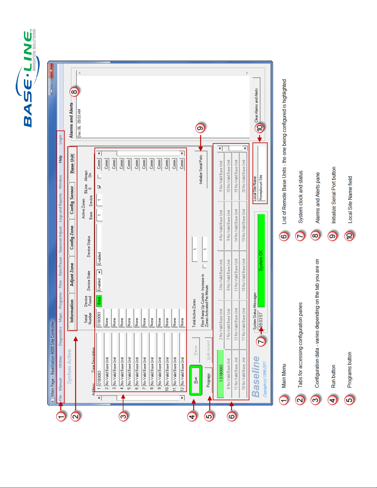
Features of the BaseStation 6000 Main Window
2
Page 3
Step One: Set Up the Remote Base Units
1. Using the designated communication method, connect the computer that is operating as your BaseStation
6000 site controller to the Remote Base Unit (RBU) or Bridge Unit.
2. Turn on the computer. The BaseStation 6000 software starts automatically.
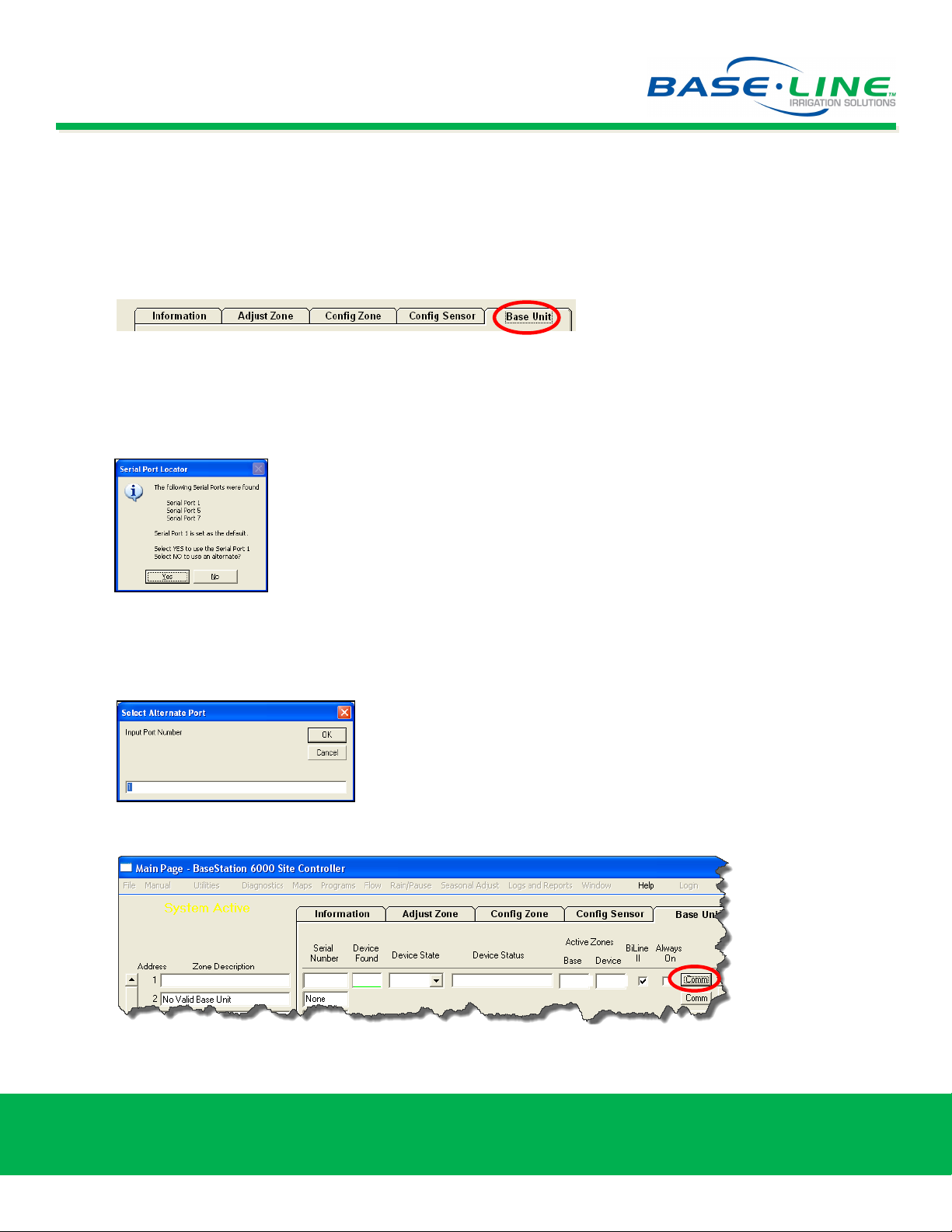
3. On the Main Page, click the Base Unit tab.
4. If the BaseStation 6000 computer connects to the RBU through a network, skip to Step 6. If the computer is
connected with a cable, continue with Step 5.
5. Click the Initialize Serial Ports button in the lower-right corner of the Base Unit tab. The computer “talks”
to the RBUs through the serial ports. The Serial Port Locator message box displays all available serial ports.
Note: If the computer was purchased from Baseline, there is
likely only one available serial port.
If the list of serial ports and the default displayed in the message box is correct, click Yes.
If the serial port is not correct, click No. The Select Alternate Port dialog box displays. Type the serial
port number in the field, and then click OK. If you need help, please consult with your IT Department or
call Baseline Technical Support (866.294.5847).
6. On the Base Unit tab, click the Comm button located at the right end of the row for the first RBU.
No Valid Base Unit
None
Baseline Inc.
Phone: 866.294.5847 · Fax: 208.323.1834 · www.baselinesystems.com
3
Page 4
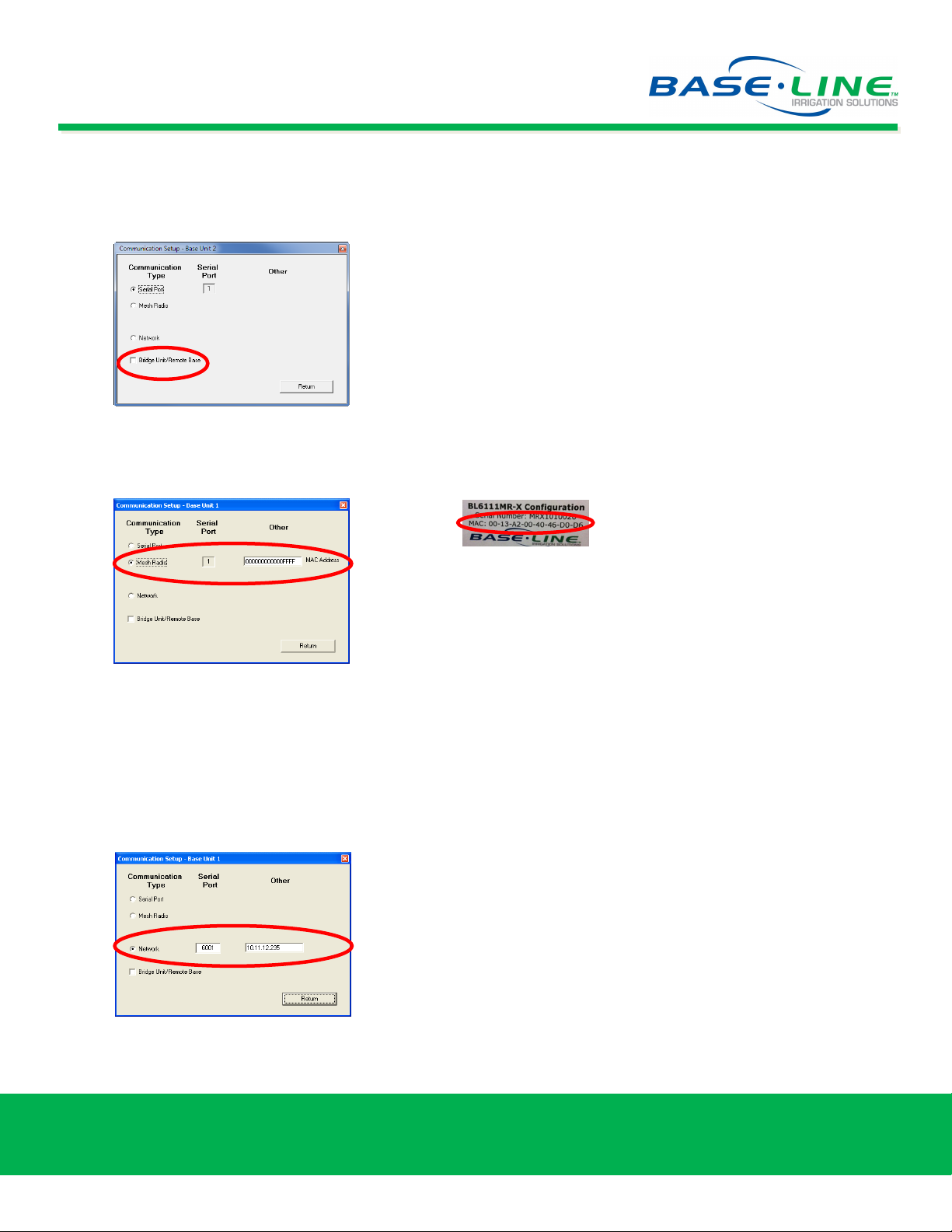
7. In the Communication Setup dialog box, select the Communication Type for the RBU.
If a serial to wired backbone Bridge Unit is part of the system configuration, be sure to select the check
box in the Communication Setup dialog box for each RBU that you are setting up.
If Mesh Radio is the Communication Type for the selected RBU, select that option, and then type the
MAC address that is listed on the Mesh Radio Module of the RBU.
Mac Address found on the
Mesh Radio Module sticker
If Radio to Radio to Bridge is the Communication Type for the selected RBU, select the Mesh Radio
option, and then type the MAC address that is listed on the Mesh Radio Module of the RBU. Also select
the Bridge Unit/Remote Base check box at the bottom of the Communication Setup dialog box.
If Network is the Communication Type for the selected RBU, select that option, and then type the serial
port number and the IP address for your network.
8. Click Return to save your changes and go back to the Base Unit tab.
Baseline Inc.
Phone: 866.294.5847 · Fax: 208.323.1834 · www.baselinesystems.com
4
Page 5

10. In the Serial Number field (1), type the serial number for the first RBU, and then press Enter. The system
searches for the device, and updates the Serial Number and Device Found fields.
Note: The RBU serial number is printed on a sticker that is located on the inside door panel of the RBU. The
serial number format is RBXXXXXXX (where the Xs represent a series of seven numbers).
11. We recommend that you type a description in the Description field (2) so you can easily identify the RBU
that you are working with.
12. Under the Active Zones column, in the Base field (3), set the total number of zones that can run at one time
(concurrent zones) for that individual RBU to 1, which is the default value.
Note: We recommend that you initially set the number of active zones to 1 in order to test the quality of the
installation and to identify any potential problems with wiring, pipes, heads, and so on. See the Concurrent
Zone information at the end of this document. For help with concurrent zone settings, please call Baseline
Support at 1.866.294.5847.
13. Repeat Steps 6-12 for each RBU.
14. In the Total Active Zones field (4), set the total number of zones that the entire system can run at one
time to 1.
15. In the Local Site Name field (5), type the name of the site.
Baseline Inc.
Phone: 866.294.5847 · Fax: 208.323.1834 · www.baselinesystems.com
5
Page 6

Step Two: Enter the Baseline biCoder Addresses for the Zones
1. Click the Config Zone tab on the Main Page of the BaseStation 6000 software.
2. Find the serial number of each biCoder. The number of the two-wire biCoder is printed on a sticker that is
attached to the side of each biCoder. The serial number of the powered biCoder is located on the inside of the
enclosure door.
Note: The package contains two
extra label stickers that you can
attach to your site plans for
future reference.
3. Make sure you know what zone each biCoder is attached to.
4. Starting with the biCoder for zone 1, double-click in the box in line 1 under the Serial Number column for
Address line 1.
5. Type the serial number for the zone 1 biCoder, and then press Enter. The Configuration Status message
displays.
6. Click OK. Additional programming fields display.
7. Type a description for the zone so you can easily identify it.
8. Assign a program number to the zone in the Prog# field.
Note: Program numbers
must be unique on each
Remote Base Unit (RBU).
For example, if RBU 1 has
programs numbered 1, 2,
and 3, then RBU 2 will have
programs numbered 4, 5,
and 6.
9. Repeat Steps 1 through 8 for all biCoders and zones that are attached to the specific RBU that you are
configuring.
Baseline Inc.
Phone: 866.294.5847 · Fax: 208.323.1834 · www.baselinesystems.com
6
Page 7

Step Three: Set Up the Start Times and Water Windows for the Programs
1. On the Main Page, click the Programs button (1) located below the Zone Description column.
2. On the Set Watering Program Schedule window, click the Water Window tab (2).
3. Click the arrow at the end of the Program field (3), and then select the program from the list that displays.
If you want to change
the name of the
program, click the
button (4) labeled
Click to Edit Program
Name.
The Program Name
dialog box displays.
Type a new name (up
to 20 characters long)
in the field, and then
click OK.
Baseline Inc.
Phone: 866.294.5847 · Fax: 208.323.1834 · www.baselinesystems.com
7
Page 8

4. Select the Enable Program check box (5).
5. Select the Enable Clock Mode with Timed Watering Starts check box (6).
6. Click the squares for the time of day when watering is allowed:
Blue allows watering during that hour.
White does not allow watering.
Note: Typically, all squares except the start times would be blue unless there are watering restrictions or
you need to designate a time for mowing.
7. Choose the watering start time for each day by clicking the appropriate square for each day and time until
that square shows green.
Note: You can only set start times in blue squares.
Hint: Click one side of the blue and white icon [ ] at the top of each column to set the entire
column blue or white. When a column is blue, you can click the green icon [ ] at the bottom of
the column to turn the entire column green.
Baseline Inc.
Phone: 866.294.5847 · Fax: 208.323.1834 · www.baselinesystems.com
8
Page 9

8. For the initial configuration, we recommend that the Total Active Zones field (7) be set to 1. Please see the
Concurrent Zone information at the end of this document.
9. Click the Return/Save button (8) at the bottom-right of the Set Watering Program Schedule window.
Hint: The information in the fields to the right of the Watering Time grid (9) provides a summary
of the settings for a selected RBU. If you want to see the settings for a different RBU, click the
arrow at the end of the Base Unit field and select an RBU from the list.
Baseline Inc.
Phone: 866.294.5847 · Fax: 208.323.1834 · www.baselinesystems.com
9
Page 10

Step Four: Adjust the Zone Run Time
1. On the Main Page, click the Adjust Zone tab (1).
2. Under the Sprinkler Settings column, set the total minutes on (2) for each zone. For more information
about this setting, see the note on Intelligent Soak Cycles at the end of this document.
Note: The Soak Cycle settings (3) are set to default values. While you can change those values, we
recommend, at least initially, that you use the default soak cycle values.
3. Click Run (4) to start the system.
Congratulations!
You are now ready to water.
Baseline Inc.
Phone: 866.294.5847 · Fax: 208.323.1834 · www.baselinesystems.com
10
Page 11

An Important Note on Concurrent Zones
Using concurrent zone settings, you can configure the controller to allow more than one zone to water at once. The
BaseStation 6000 uses a sophisticated watering engine that can use concurrent zone settings on multiple levels
including the device level, program level, Base Unit level, and system wide level. These settings require detailed
information about the electric and hydraulic limits of the system.
During the initial configuration of your BaseStation 6000, we recommend that you set all concurrent zone
settings to one, which limits the number of zones that can run at one time to only one. If you are unsure where
these settings are configured, please call Baseline Support.
If your site requires that more than one zone waters at once, and you know the gallons per minute available from
your sources and the gallons per minute output of each zone, you can set each of those limits appropriately. For
example, if you know that your water source provides 100 gallons per minute, and each zone waters at a maximum
of 25 gallons per minute, then your available concurrent zones would be 4.
We strongly recommend that you call Baseline Support when configuring concurrent zone so we can help optimize
your system’s watering capabilities. We look forward to your call. We can be reached at 1.866.294.5847.
An Important Note on Intelligent Soak Cycles
Soak cycling breaks the total run time (the time set in the Total Min On field) into shorter water “cycles” (timed
water applications) with “soak” periods in between to allow time for water to soak into the soil before applying more
water. Soak cycles save water by avoiding surface soil saturation and runoff.
Even on a perfectly designed system,
it is important to match the water
application rate to the infiltration rate
of your soil. You configure this by
breaking the total run time for any
zone into multiple cycles and soaks.
The BaseStation 6000 has built-in support for soak cycling and uses intelligent watering algorithms that apply cycles
in the optimal order to maximize water penetration and minimize evaporation loss.
To understand how this works, consider the settings in the example below:
Total Min On = 60 minutes
Minutes On = 10 minutes
Soak = 30 minutes
In this scenario, the system waters for 10 minutes, and then it turns off and allows that water to soak in for 30
minutes. The system repeats this cycle 6 times to complete the total of 60 minutes set in the Total Min On field.
Note: One easy way to determine
good cycle times is to turn on a zone
and watch for first signs of standing
water or runoff. Set the cycle time to
be no more than this amount of time.
Thanks for choosing Baseline!
Baseline Inc.
Phone: 866.294.5847 · Fax: 208.323.1834 · www.baselinesystems.com
11
 Loading...