

Page 1
BL-3200WF-X Wi-Fi Module for X/XS Cabinet
Installation Guide
Required Tools
Phillips screwdriver
Needle-nose pliers
Crescent wrench
Installing the Wi-Fi Module
1. Remove all parts from the packaging.
2. Power down the controller.
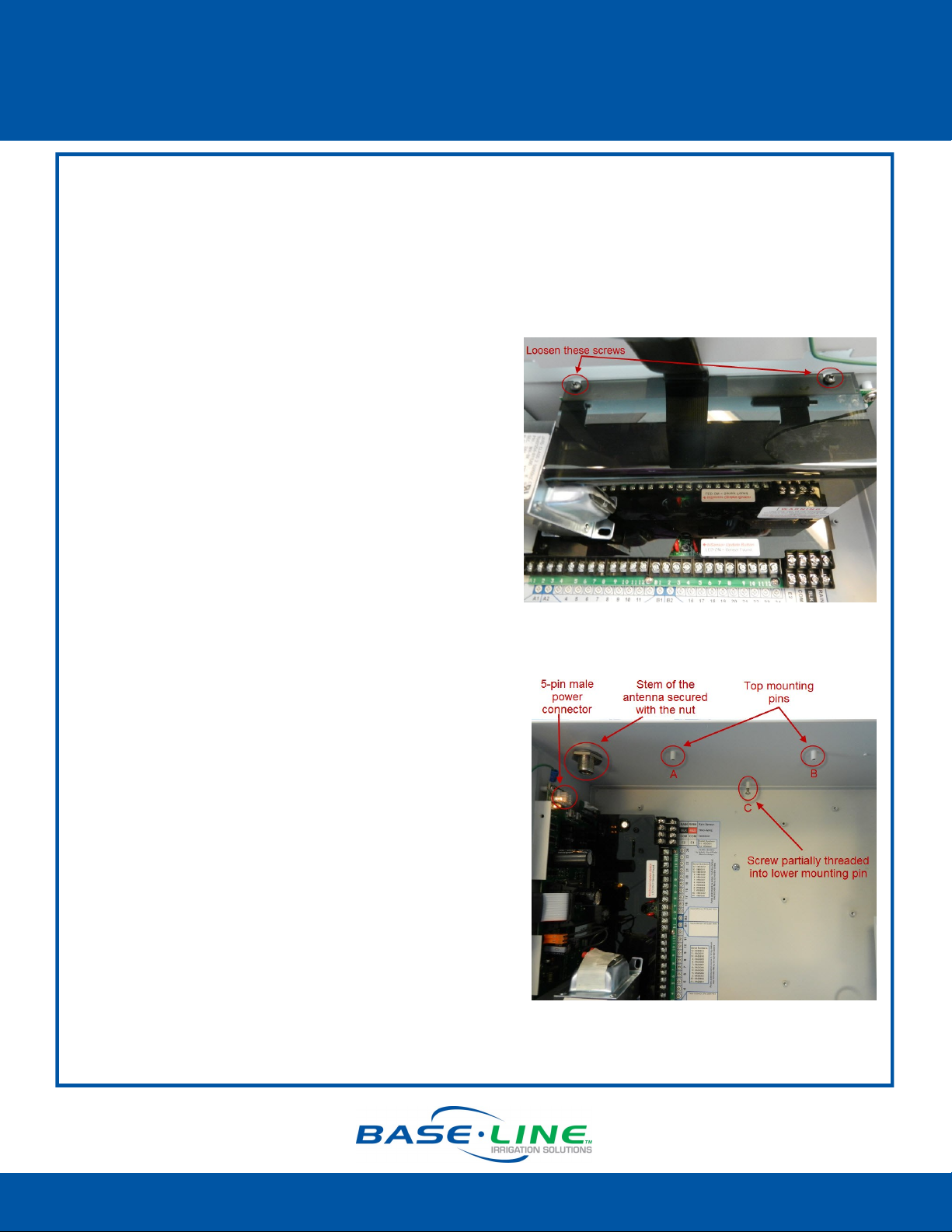
3. Loosen the two screws on the top of the control
board cover.
4. Carefully remove the cover and set it aside.
5. Use needle-nose pliers to remove the rubber
plug from the antenna port on the top of the
cabinet.
6. Remove the nut and the lock washer from the
bottom of the antenna, and then insert the stem
of the antenna into the port on the top of the
cabinet.
7. From the inside of the cabinet, place the lock
washer on the stem of the antenna, and then
thread the nut onto the stem. Use a wrench to
tighten the nut sufficiently to ensure that the
antenna makes good contact with the outside
of the cabinet.
8. Partially thread one of the provided mounting
screws into the lower mounting pin (C) on the
inner top of the cabinet.
9. Connect the end of the antenna cable onto the
stem of the Wi-Fi module and hand-tighten it.
10. Position the notch on the edge of the Wi-Fi
module mounting plate on the partially
threaded screw (C). Tighten the screw so it holds
the mounting plate in place.
11. Align the holes on the Wi-Fi module mounting
plate with the mounting pins (A & B). Use the
screws provided to securely attach the module
inside the cabinet.
Connued
Page 1
1-866-294-5847 Rev 9.30.2014 www.baselinesystems.com
Page 2
BL-3200WF-X Wi-Fi Module for X/XS Cabinet
Installation Guide
12. Carefully turn the Wi-Fi module in the
mounting bracket so the indicator lights are
visible.
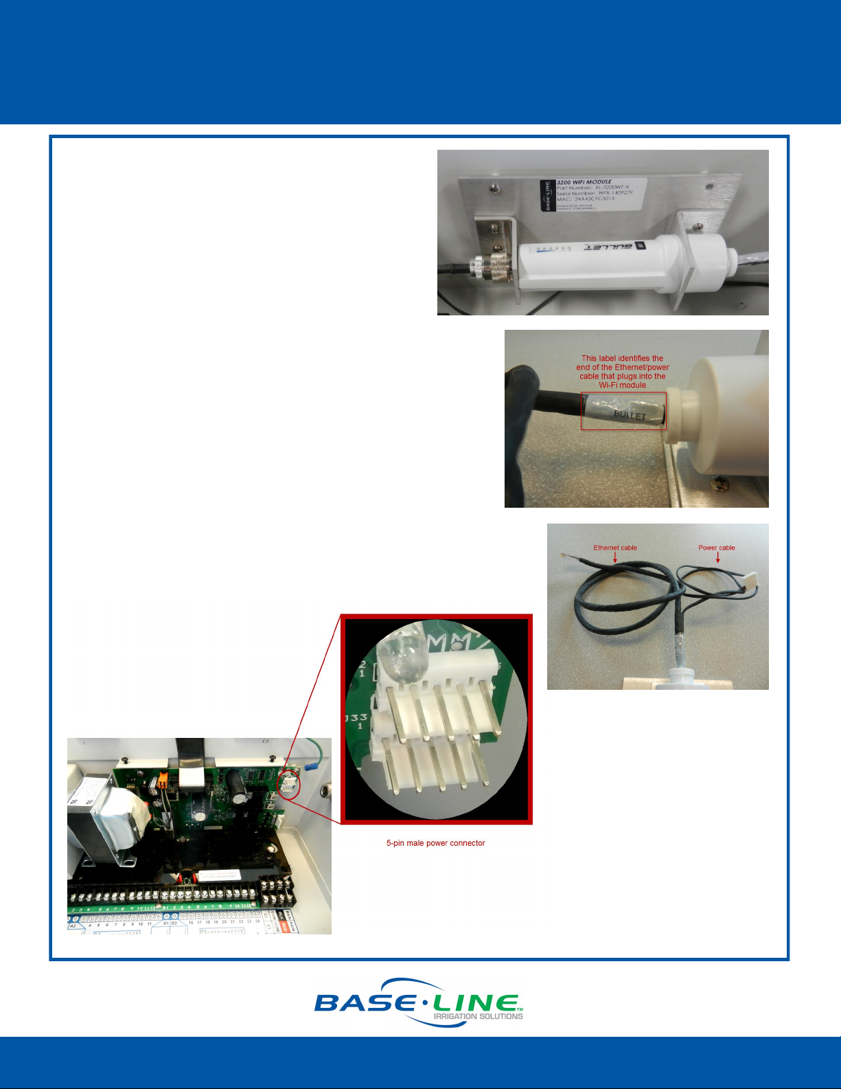
13. Inspect the cable coming from the right end
of the Wi-Fi module. A label identifies the
RJ45 connector that is plugged into the Wi-Fi
module. If you ever need to disconnect or
replace this cable, make sure to plug the
labeled end into the Wi-Fi module. This cable
supplies power over Ethernet and plugging it in
incorrectly will damage the irrigation controller.
14. Notice that the cable coming from the right end of
the Wi-Fi module splits in two. The thin cable with the
white connector is the power cable. The thicker
cable is Ethernet.
15. Inspect the power cord to ensure that it is not
wrapped around the Ethernet cable. If it is, unwrap
it.
16. Plug the 5-pin connector on the power cable into
one of the 5-pin male power connectors on right
end of the controller board.
Connued
Page 2
1-866-294-5847 Rev 9.30.2014 www.baselinesystems.com
Page 3

BL-3200WF-X Wi-Fi Module for X/XS Cabinet
Installation Guide
17. Gently gather the antenna cable into two loops, and
then connect the end of the antenna cable onto the
stem of the antenna and hand-tighten it.
IMPORTANT! Do not bend or kink the antenna
cable.
18. Keep the antenna cable looped, and then reposition
the control board cover so it covers the antenna
cable and holds it in place.
19. Tighten the screws on the control board cover.
20. Remove the paper backing on the adhesive on the
cable clip, and then attach the cable clip to the
control board cover as shown in the illustration.
21. Secure the Ethernet cable under the cable clip, and
then plug the end of the Ethernet cable into the
Ethernet jack on the back of the controller’s
faceplate.
22. Check the connectors on the antenna cable on the
antenna end and the Wi-Fi module end to make sure
they are tight.
IMPORTANT! Make sure the antenna cable remains
securely attached to the connector on the Wi-Fi
module. If the module is powered up with a loose or
disconnected antenna, damage may occur to the
circuitry. This damage is not covered by warranty.
23. Power up the controller.
24. Make sure the indicator lights on Wi-Fi module are
illuminated.
25. Follow the instructions in the Wi-Fi Module
Configuration Guide to complete the setup in the
controller.
Page 3
1-866-294-5847 Rev 9.30.2014 www.baselinesystems.com
Page 4

BL-3200WF-X Wi-Fi Module for X/XS Cabinet
Installation Guide
Troubleshooting Tips
If the Wi-Fi module is not performing as expected, you might need to try the following
troubleshooting steps.
Make sure the antenna cable is not bent or kinked in any way. You might need to remove the
control board cover to see the antenna cable.
Make sure the RJ45 connector is properly seated in the
end of the Wi-Fi module. You can gently push the end of
the Ethernet cable and it toward the Wi-Fi module to
ensure that it is seated properly.
The photo on the right shows how the connector is
plugged into the Wi-Fi module inside the weatherproof
cover.
Reset the Wi-Fi module to factory settings.
Perform these steps if network settings change or if you need
to connect to a different network.
1. Power down the controller.
2. Remove the control board cover and disconnect the
antenna cable from the antenna.
3. Disconnect the Wi-Fi module power cable.
4. Disconnect the Ethernet cable from the back of the
faceplate.
5. Remove the screws on the Wi-Fi module mounting plate.
6. Remove the Wi-Fi module from the cabinet and unscrew
the cover from the end where the Ethernet cable is
plugged in. The gasket will pop out. Be sure to set it aside
so you can reuse it.
7. Reconnect the antenna cable, the power cable, and the
Ethernet cable.
8. Power on the controller.
9. Use a pointed object to press and hold the Reset button
until all the lights flash, and then release the button.
10. Reattach the connector cover and replace the gasket.
11. Reattach the Wi-Fi module mounting plate inside the
cabinet.
12. Replace the control board cover.
13. Follow the instructions in the Wi-Fi Module Configuration
Guide to reconfigure the Wi-Fi module.
Page 4
1-866-294-5847 Rev 9.30.2014 www.baselinesystems.com
 Loading...