

Page 1
BL-3200WF-P Wi-Fi Module for Pedestal
Installation Guide
Required Tools
Phillips screwdriver
Needle-nose pliers
Crescent wrench
Hobby knife with a fine point and sharp blade
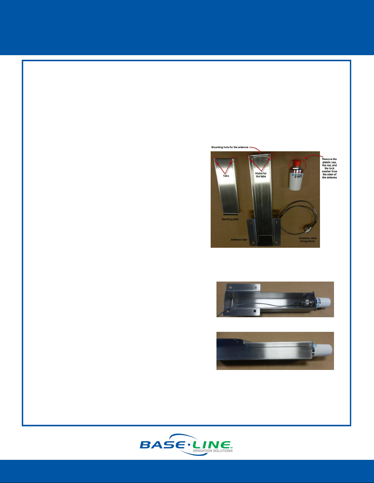
Assemble the Antenna Riser
1. Remove the antenna assembly and antenna
from its packaging.
2. Set the short piece of antenna cable aside to be
used in a later step.
3. Remove the plastic cap, the nut, and the lock
washer from the stem of the antenna.
4. Put the stem of the antenna through the
mounting hole on the top of the antenna riser so
the antenna is positioned on top of the riser.
5. Put the lock washer onto the stem of the
antenna, and then thread the nut onto the
stem. Use a wrench or pliers to tighten the nut
sufficiently to ensure that the antenna makes
good contact with the outside of the antenna
riser.
6. Thread the coax connector on the antenna
cable onto the stem of the antenna and handtighten it. Route the antenna cable towards the
bottom of the antenna riser.
7. Insert the tabs on the backing plate into the
holes at the top edge of the riser and make sure
the plate is snug along the back of the riser.
Connued
Page 1
1-866-294-5847 Rev 10.9.2014 www.baselinesystems.com
Page 2
BL-3200WF-P Wi-Fi Module for Pedestal
Installation Guide
Prepare the Mounting Location for the
Antenna Riser
1. Open and remove the front door on the lower
part of the pedestal.
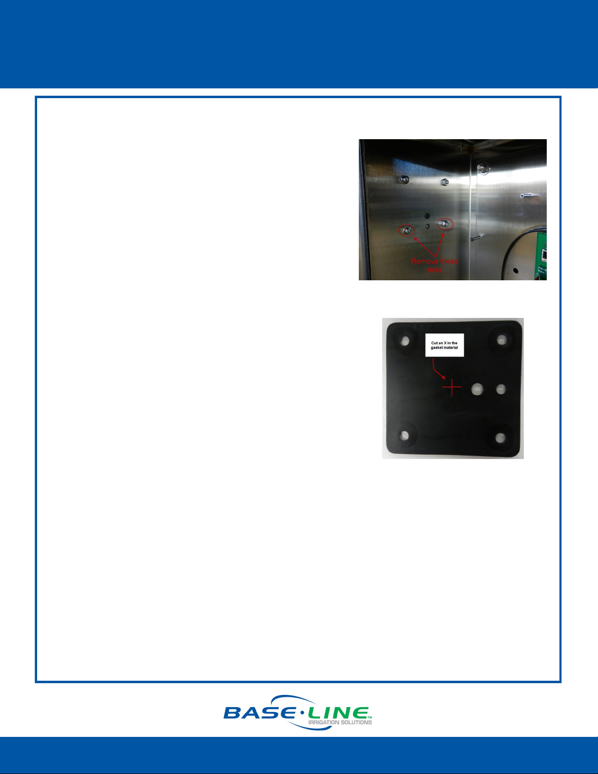
2. On the inside left wall of the pedestal, remove
the nuts from the bolts that secure the cover on
the outside wall. Set the nuts aside to be
replaced in a later step.
3. Remove the bolts that are holding the cover on
the outside wall. Set the bolts aside to be
replaced in a later step.
4. Remove the cover from the outside wall, making
sure that the gasket stays in place.
5. On the inside left wall of the pedestal, find the
opening that is covered by the gasket. Use a
sharp hobby knife to poke a small hole to mark
the center of the opening.
6. Remove the gasket and place it on a solid
surface. Use the hobby knife to cut a small X that
intersects the small hole that you made. Make
each cut approximately ½ inch long.
Note: This opening is used to route the
antenna cable inside the pedestal in order to
connect it to the cell modem. Make the X
large enough to pass the cable through, but
small enough to maintain the seal.
7. Position the gasket on the outside wall of the
pedestal so the bolt holes are aligned and the
small X is aligned with the opening for the
antenna cable.
Note: You’ll need to hold the gasket in place
while you attach the antenna riser in the next
step. For this part of the procedure, it’s nice
to have a helper.
Connued
Page 2
1-866-294-5847 Rev 10.9.2014 www.baselinesystems.com
Page 3

BL-3200WF-P Wi-Fi Module for Pedestal
Installation Guide
Attach the Antenna Riser to the Pedestal
1. Feed the free end of the antenna cable through
the small X that you made in the gasket and into
the inside of the pedestal.
2. Align the holes at the bottom of the antenna
riser with the holes in the gasket at the mounting
location on the outside left wall of the pedestal.
3. Working from the outside of the pedestal, insert
the bolts that you removed earlier into the four
holes.
4. Working from the inside of the pedestal, thread
the nuts that you removed earlier onto the four
bolts. Tighten the nuts snugly.
Attach the Antenna Cable Adapter
1. Working from the inside of the pedestal, thread
the brass end of the antenna cable adapter into
the end of the long antenna cable. Tighten the
connection securely.
2. Connect the other end of the antenna cable
adapter onto the stem of the Wi-Fi module and
hand-tighten it.
3. You can gently push the excess length of
antenna cable back through the pedestal wall
so it is held within the antenna riser.
IMPORTANT! Do not bend or kink the antenna
cable.
Connued
Page 3
1-866-294-5847 Rev 10.9.2014 www.baselinesystems.com
Page 4

BL-3200WF-P Wi-Fi Module for Pedestal
Installation Guide
Install the Wi-Fi Module
1. Power down the controller.
2. Align the holes on the Wi-Fi module mounting
plate with the standoffs to the left of the control
board. Use the screws provided to securely
attach the module inside the pedestal.
3. If necessary, carefully turn the Wi-Fi module in
the mounting bracket so the indicator lights are
visible.
4. Inspect the cable coming from the bottom of
the Wi-Fi module. A label identifies the end of
the cable that is plugged into the Wi-Fi module.
If you ever need to disconnect or replace this
cable, make sure to plug the labeled end into
the Wi-Fi module. This cable supplies power over
Ethernet, and it must be plugged in correctly or
the irrigation controller can be damaged.
5. Notice that the cable coming from the bottom
of the Wi-Fi module splits in two. The thin cable
with the white connector is the power cable.
The thicker cable is Ethernet.
6. Inspect the power cord to ensure that it is not
wrapped around the Ethernet cable. If it is,
unwrap it.
Connued
Page 4
1-866-294-5847 Rev 10.9.2014 www.baselinesystems.com
Page 5

BL-3200WF-P Wi-Fi Module for Pedestal
Installation Guide
7. Plug the 5-pin connector on the power cable
into one of the 5-pin male power connectors
on right end of the controller board.
8. Plug the end of the Ethernet cable into the
Ethernet jack on the back of the controller’s
faceplate.
9. Check the connectors on the antenna cable
on the antenna end and the Wi-Fi module end
to make sure they are tight.
10. Power up the controller.
11. Make sure the indicator lights on Wi-Fi module
are illuminated.
12. Follow the instructions in the Wi-Fi Module
Configuration Guide to complete the setup in
the controller.
IMPORTANT! Make sure the antenna cable remains
securely attached to the connector on the Wi-Fi
module. If the module is powered up with a loose or
disconnected antenna, damage may occur to the
circuitry. This damage is not covered by warranty.
Page 5
1-866-294-5847 Rev 10.9.2014 www.baselinesystems.com
Page 6

BL-3200WF-P Wi-Fi Module for Pedestal
Installation Guide
Troubleshooting Tips
If the Wi-Fi module is not performing as expected, you might need to try the following
troubleshooting steps.
Make sure the antenna cable is not bent or kinked in any way.
Make sure the RJ45 connector is properly seated in the
end of the Wi-Fi module. You can gently push the end of
the Ethernet cable toward the Wi-Fi module to ensure
that it is seated properly.
The photo on the right shows how the connector is
plugged into the Wi-Fi module inside the weatherproof
cover.
Reset the Wi-Fi module to factory settings.
Perform these steps if network settings change or if you need
to connect to a different network.
1. Power down the controller.
2. Remove the control board cover and disconnect the
antenna cable from the antenna.
3. Disconnect the Wi-Fi module power cable.
4. Disconnect the Ethernet cable from the back of the
faceplate.
5. Remove the screws on the Wi-Fi module mounting plate.
6. Remove the Wi-Fi module from the cabinet and unscrew
the cover from the end where the Ethernet cable is
plugged in. The gasket will pop out. Be sure to set it aside
so you can reuse it.
7. Reconnect the antenna cable, the power cable, and the
Ethernet cable.
8. Power on the controller.
9. Use a pointed object to press and hold the Reset button
until all the lights flash, and then release the button.
10. Reattach the connector cover and replace the gasket.
11. Reattach the Wi-Fi module mounting plate inside the
cabinet.
12. Replace the control board cover.
13. Follow the instructions in the Wi-Fi Module Configuration
Guide to reconfigure the Wi-Fi module.
Page 6
1-866-294-5847 Rev 10.9.2014 www.baselinesystems.com
 Loading...