

Page 1
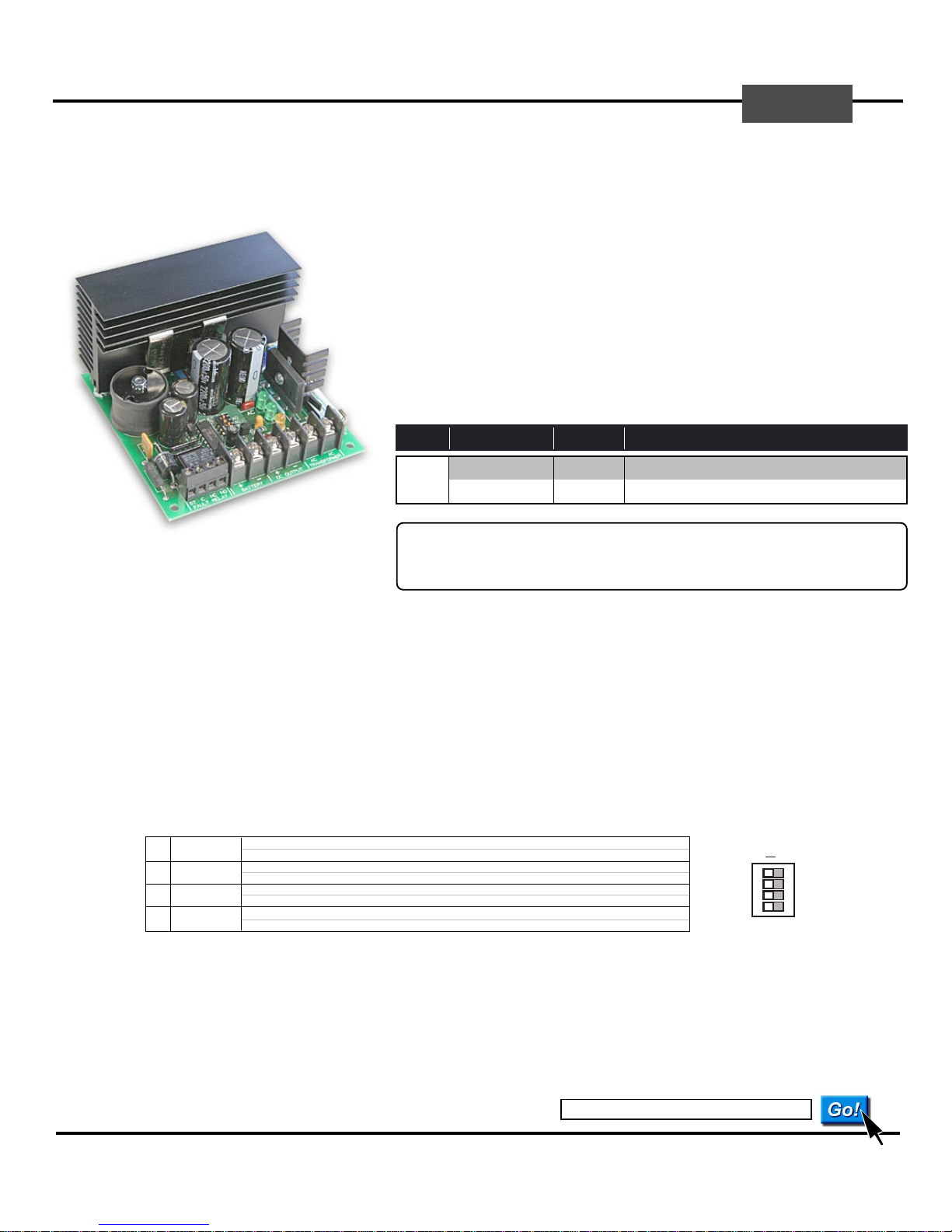
XP5 DC Power Supply and Battery Charger
BASE
5 Amp High Current Output5 Amp High Current Output
Features
• Regulated 12VDC or 24VDC output at up to 5 Amps supply current
• Output Voltage is Single-Switch Selectable and Adjustable
• Selectable Power Monitor Alarm with 2A dry contact output
• Charges lead acid gel cell batteries - includes battery cable kit
• Uninterrupted output on switch over to/from standby battery
• Status LEDs for AC input, DC output and Fault conditions
• Separately fused AC input and Battery circuits
• Current limit, thermal overload and output short protection
• Small Footprint PCB - 4.00”w x 4.00”l x 2.38”h
• Includes Mounting Hardware
OUTPUT
VOLTAGE CURRENT
12 VDC 5.0 A 20 AH
24 VDC 5.0 A 20 AH
Installation Instructions
MODEL
XP5
Turn off all power feeding the module terminals before installing, servicing or changing any switch settings, wiring, battery
or fuses. Failure to observe this warning may cause electrical shock hazard or may damage internal or external circuit
components. Various components of the unit will become hot during normal operation of the unit. Locate the unit away
from cabling or other objects that may be affected or damaged by this heat dissipation. Use caution while working near the
unit during normal operation - components can be hot enough to cause serious burns.
Install in accordance with applicable sections of the National Electrical Code and other State or Local Regulations.
1. Mounting the Board Locate the unit inside a UL Listed NEMA 1 enclosure (such as a BASE LVPC Low Voltage Power Cabinet). Drill or punch
four 0.187" diameter holes (3/16”) to match the four corner holes in the printed circuit board. Push the nylon standoffs supplied into each hole and snap
the PCB module into place. Mounting with double-sided tape is not recommended.
BATTERY
MAX AH
* * *
TRANSFORMER REQUIREMENTS
Transformer Output: 28-32 VAC, 100 VA Minimum
BASE XF29218
Transformer Output: 28-32 VAC, 150 VA Minimum
BASE XF29218
WARNING
INPUT: 120 VAC, 2.50 A OUTPUT: 29 VAC, 7.5 A, 218 VA
BLACK & WHITE WIRES WHITE WIRES
INPUT: 120 VAC, 2.50 A OUTPUT: 29 VAC, 7.5 A, 218 VA
BLACK & WHITE WIRES WHITE WIRES
* * *
2. Transformer Wiring See Transformer Selection above. Connect Transformer output wires to the two Transformer
AC terminals.
3. DC Output Setup Set the Output Voltage Switch for the desired output - 12 or 24 VDC. With no load or battery wiring connected, turn on the AC
power source. The AC and DC green LEDs will light. Next, measure the voltage at the DC Output terminals with a voltmeter. The output voltage is
factory set to approx. 13.5 vdc or 27.0 vdc - ideal settings for charging batteries. However, if a field adjustment is desired, use a small screwdriver to
slowly adjust the output voltage at the potentiometer labeled ADJ. (If no batteries are being used - adjust down to 12 vdc or 24 vdc). Then turn off the
AC power source before proceeding with the installation.
4. Power Monitor Setup and Fault Relay Ouput Terminals Set the Option DIP Switches for the desired Power Monitor Options.
Power Monitor
PM
Enable/Disable
BA
AC
AD
Battery
Supervision
AC Power
Supervision
10 Second
Alarm Delay
ON = Enables PM Alarm Relay and DC Output supervision for DC Power Failure, Shorted, or Low
OFF = Power Monitor Off - Reduces No-Load Current Draw by 35 mA.
ON = Enables Battery Set supervision for Low or Shorted Battery, or Blown Battery Fuse
OFF = No Battery Supervision
ON = Enables AC Power Supervision for AC Power Failure or Blown AC Fuse
OFF = No AC Power Supervision
ON = Enables a 10-second Fault Alarm delay for masking short AC power failures or low battery alarms.
OFF = Fault Alarms are instantly activated.
POWER SUPV
ON OFF
AD
AC
BA
PM
The Fault Alarm Relay is energized when no selected fault condition exists. The relay de-energizes and the Fault LED flashes when one or more
selected Fault Conditions are present. Terminals of the relay contacts are labeled for when the relay is in Alarm. The ST terminal is a Spare Terminal
that can be used as an easy splice point for an end-of-line resistor when monitoring the fault relay with a supervised circuit. Contact Rating is 2 Amps.
5. DC Output Wiring Connect output wiring to the DC OUTPUT terminals. Observe and verify correct DC polarity before powering the unit.
6. Battery Wiring Maximum standby batteries - 20 Ampere Hours. Connect battery wiring to battery terminals of the Power Supply first. Observe
and verify correct DC polarity before proceding to next step. Incorrect polarity will blow the
BATTERY FUSE.
7. Power Up Connect DC output load wiring. Re-check all connections and turn on the AC power source. Connect battery wiring to battery.
www.baseelectronics.com
BASE Electronics, Inc. • 2856-C Janitell Road • Colorado Springs, CO 80906 • (719) 540-9697 • Fax (719) 540-9698
Page 2
AC FUSE 10A
ST C NC NO
+-+-
AC AC
BATTERY DC OUTPUT TRANSFORMER
POWER SUPV
ON - OFF
AD
PM
AC
FAULT RELAY
AC
DC
FAULT
G
G
Y
BA
XP5
BASE
DC POWER SUPPLY
AND BATTERY CHARGER
12
24
ADJ
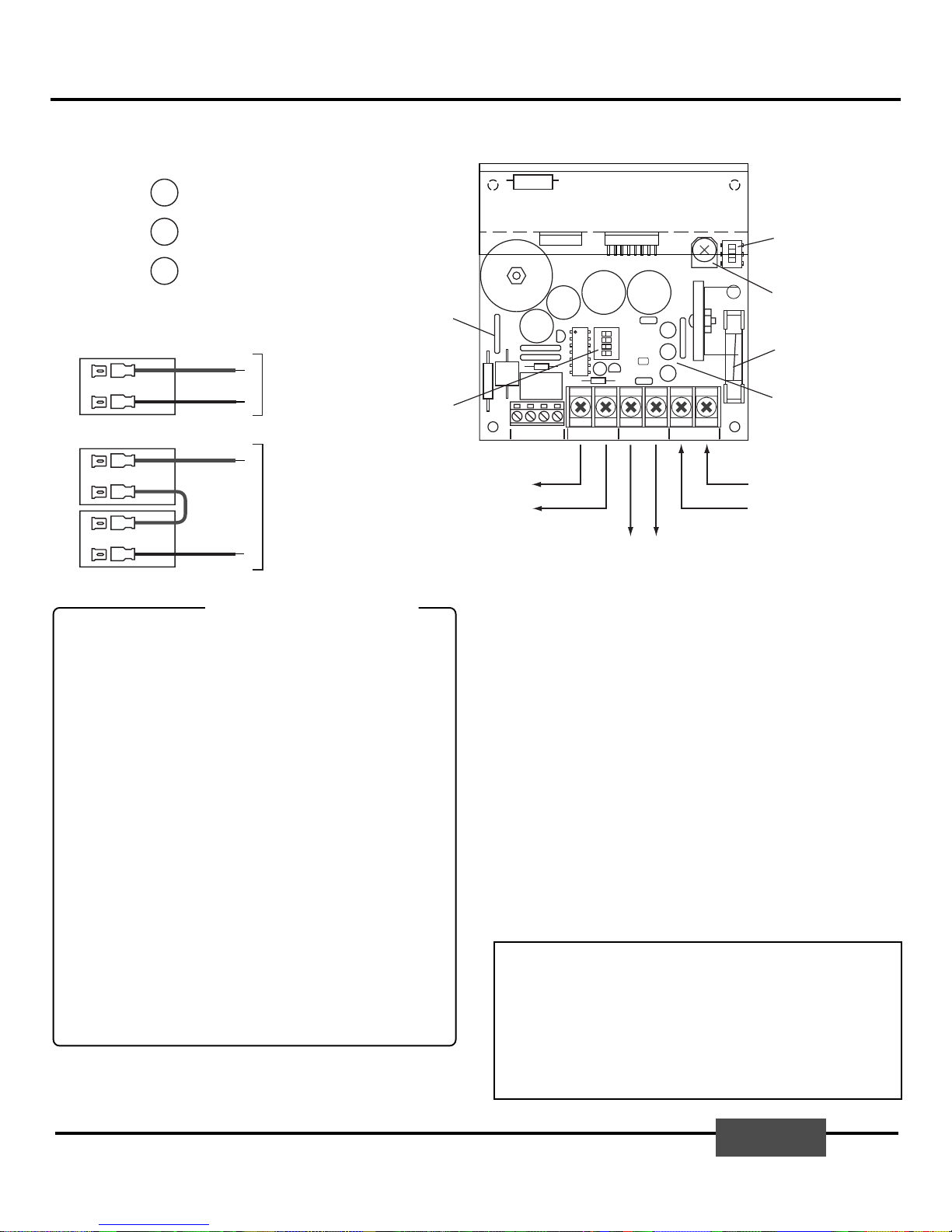
Output Voltage Switch
Voltage Adjustment
12vdc (11.5 - 14.0)
24vdc (23.0 - 28.0)
AC Input Fuse - 10A
Battery Resetable Fuse - 5A
Power Monitor Options
LED Status Indicators
28-32 VAC Input
From Transformer
To Standby Battery
DC Output
to Devices
+ -
+
-
XP5 DC Power Supply and Battery Charger
Power Status LED Indicators
Green (G), Yellow (Y)
AC POWER
DC POWER
FAULT
Battery Wiring - 12 VDC
+
12V Battery
-
Battery Wiring - 24 VDC
+
12V Battery
-
+
12V Battery
-
Calculating Total Current Draw
Total
Current Draw
The Total Current Draw must not exceed 5 Amps, or the power supply may
overheat. The XP5 has built-in current limit/thermal overload protection
and the DC output will turn off if either occurs. A better design guidline (to
prevent early power problems and extend the life of power supplies and
batteries) is to limit the calculated draw to 50-75% of Max. (2.50-3.75A),
especially when charging batteries. Also, future system expansion should
be considered in your load calculations.
Cable Resistance
When powering devices over considerable distances, cabling resistance
may be so high that the voltage available at the device has dropped to an
unacceptable level. To prevent this from occuring, system cabling should
be designed with adequate sized conductors.
Heat Buildup
A by-product of all step-down power supplies/regulators/transformers is
heat. Continuously pushing power supplies to their limits will maximize
heat dissipation and buildup within power cabinets - which will thereby
work to reduce the life of these components. Consider their location or the
use of cabinet grills or fans to reduce heat buildup.
Power Distribution
Separately fusing output devices or groups of output devices greatly
reduces trouble-shooting efforts. The larger the power supply and number
of devices powered, the greater the need for power distribution. BASE has
a variety of power distribution products that help speed installations while
providing easier maintenance and a custom professional appearance.
The information in this manual is believed to be accurate in all respects. However, BASE Electronics cannot
assume responsibility for any consequences resulting from the use thereof. The information contained herein is
subject to change and BASE Electronics may issue a revision to incorporate such changes at any time.
G
G
Y
ON = AC power from transformer present.
OFF = AC power fault/failed.
ON = DC output power present.
OFF = DC power fault/failed..
FLASH = Selected fault condition present.
OFF = No fault condition.
RED
BLACK
RED
YELLOW
JUMPER
BLACK
+
-
+
-
To Power Supply
Battery Terminals
To Power Supply
Battery Terminals
Power System Design Tips
+ No-load Current Draw (See Specifications)
+ Max Battery Charge Current (See Specifications)
=
+ Estimated Load Current of Powered Devices
+ Estimated Load Current (for Future Expansion)
XP5 Specifications
• Indoor Temperature Range: -25° C. to +70°C.
• Electrical
AC Input: 28-32 VAC, 50-60 Hz
Maximum Output: 13.8 or 27.6 VDC, 5A (at 25°C)
Maximum No-Load Current Consumption: 80mA (0.080 A)
Maximum Battery Charge Current : 450mA (0.450 A)
Battery Type: Sealed Lead Acid Gel Cell Type Only
Fault Supervision Relay Form-C Contact Rating: 2A
Connections: Captive Screw Terminals for #14 to #22AWG Wire
AC Input Fuse: 10A, Type 3AG, Fast Blow
Battery Rettable Fuse: 5A
• Size: 4.00 wide by 4.00 long by 2.38 high (inches)
• Mounting: (4) 1/4 inch high nylon standoffs included
• Controls and Indicators
Output Voltage is Single-Switch selectable and adjustable: 12 or 24 VDC
Fault Supervision Select 4-pole Dip Switch: PM, BA, AC, AD
3 LED Indicators for AC Power (Green), DC Power (Green), Fault (Flashing Yellow)
• Special Features
On-board selectable Fault Supervision with Relay Form-C Contact Ouput
Charger for Lead Acid Gel Cell Batteries
Separately fused AC input and Battery circuits
This XP Series DC Power Supply Module is warranted by BASE Electronics against manufacturing defects in materials and
workmanship for a period of 2 years from date of purchase. During this period, any warranty repair required will be made at no
charge for parts or labor. This warranty does not apply to any work or materials provided by any outside persons or technicians
involved in the installation, unauthorized repair, connection, or testing of this product. This warranty does not cover any
damage or failure caused by or attributable to Acts of God, abuse, misuse, improper or abnormal usage, faulty or improper
installation or maintenance, neglect or accident. BASE Electronics is not responsible or liable for any special, consequential or
indirect damages resulting from or in connection with the use or performance of this product as pertaining to economic loss,
property loss, costs for removal or installation, or loss of revenues or profit. Except as provided herein, BASE Electronics
makes no expressed or implied warranties. The duration of product performance for its intended purpose is limited to the
duration set forth herein.
For Warranty or other repair, send the product postage prepaid to BASE Electronics and include Sender's name, company,
address, phone and brief problem description. BASE Electronics will notify sender of any required repair costs not covered
under this warranty prior to making such repairs.
This Warranty gives you specific legal rights. You may have other rights that vary from state to state.
Limited Warranty
U
LISTED
®
BASE Electronics, Inc. • 2856-C Janitell Road • Colorado Springs, CO 80906 • (719) 540-9697 • Fax (719) 540-9698
© 2005-2006 BASE Electronics, Inc.
BASE
 Loading...