

Basbau BB – 201 Blue, BB-201 Blue Digital Digital Instruction Manual

PORTABLE COLOR
LCD DIGITAL WIRELESS
MONITORING SYSTEM
INSTRUCTION MANUAL
MODEL:
BB – 201 Blue Digital
Warning to all users
Please read carefully this user manual before using the BB – 201 Blue Digital wireless monitoring system.
Failure to follow these warnings and the assembly instructions could result in serious inquiry or death.
- Keep the AC adapter cords out of the reach of children.
- Protect the AC adapter cords. Make sure that they are not walked on or pinched by furniture or
other items.
- Use ONLY the AC adapters provided in this kit. Using other 3rd parties AC adapters may cause
fatal damage to the monitoring system.
- Make sure the provided AC adapters are at the same electrical voltage of your country.
- Do not place the monitoring system or its cord within the child reach.
- Provide proper ventilation for the monitoring system when it is operating. Do not cover the
Monitor unit and Camera unit with any material, such as a blanket. Do not place the Monitor and
Camera units in a poor ventilation area, such as a drawer.
- Do not immerse the monitoring system in water. Clean it only with a dry cloth.
- Do not use the monitoring system near any possible wet areas, such as a bathtub, shower, basin,
sink, laundry tub.
- Do not use the monitoring system outdoors.
- Keep the monitoring system away from heat sources, such as fireplaces, radiators, stove.
-
Do not attempt to open the Monitor unit, Camera unit and the AC adapters. No user-serviceable
parts inside. Risk of electrical shock, fire or death.
FCC Statement
WARNING : Modifications not authorized by the manufacturer may void users authority to operate
this device.
This equipment has been tested and found to comply with the limits for a Class B digital device, pursuant to
Part 15 of FCC Rules. These limits are designed to provide reasonable protection against harmful
interference in a residential installation. This equipment generates, uses, and can radiate radio frequency
energy and, if not installed and used in accordance with the instructions, may cause harmful interference to
radio communications.
However, there is no guarantee that interference will not occur in a particular installation. If this equipment
does cause harmful interference to radio or television reception, which can be determined by turning the
equipment off and on, the user is encouraged to try to correct the interference by one or more of following
measures:
- Reorient or relocate the receiving antenna.
- Increase the separation between the equipment and receiver.
- Connect the equipment into an outlet on a circuit different from that to which the receiver is
connected.
- Consult the dealer or an experienced radio/TV technician for help.
This device complies with part 15 of the FCC Rules. Operation is subject to the following two conditions:
1. This device may not cause harmful interference, and
2. This device must accept any interference received, including interference that may cause
undesired operation.

Content
1. Specification
1
2. Part List
2
a. Monitor Unit
b. Camera Unit
3. Installation
3
a. Monitor Unit Installation
b. Camera Unit Installation
4. Operation
4
a. Power On / Off
4
b. Volume Adjustment
5
c. Brightness Adjustment
5
d. VOX / Voice Activation Function
5
e. Night Vision Function
5
f. Battery Charging
5
g. LED Indicators
6
h. Mounting
6
i. Pairing / Adding Camera Unit
8
5. Troubleshooting
9
1
1. Specification
Features :
• Digital 2.4GHz wireless transmission for both video and audio signal
• Encrypted data transfer to ensure 100% privacy
• Adopting Frequency Hopping (FHSS) technology to switch between different
channels automatically.
• Extended transmission distance up to 300m at open area.
• Supports up to 4 camera units simultaneously.
• Automatic night vision function when operating in dim area.
• Remote sound activation (VOX) from camera unit.
• Portable monitor unit with Lithium battery and built-in battery charger
Monitor unit
Display
2.4” TFT color display at 320x240 resolution
Audio
1W
Frequency
2400 – 2483 MHz (auto select by Frequency Hopping FHSS)
Pairing
Supports 4 camera units simultaneously
Switches
Power
Pairing
Volume +/- (10 steps control)
Brightness +/- (6 steps control)
LEDs
Power (green), Low Battery (flash)
Signal Coverage (blue), poor reception (flash), Battery
Charging (red)
Activation
Both manual or voice triggered (VOX) from camera unit
OSD
Brightness, Volume, Pairing selection
Battery
Lithium battery
A/C power
6V 1A DC adaptor
Mounting mechanism
Multi-purpose stand + belt clip or wall mounted
Camera unit
CMOS Sensor
1/6” VGA, 640x480
Lens
F/No 1.8, EFL 2.95mm, BFL 2.488mm
Night vision
8x IR LED
LED
Power
Flipping angle
0 – 90 degree
Swinging angle
+/- 15 degree
Microphone
built in
A/C power
6V 1A DC adaptor
Mounting mechanism
Flatbed or wall mounted
Transmitting Power
16dB
2
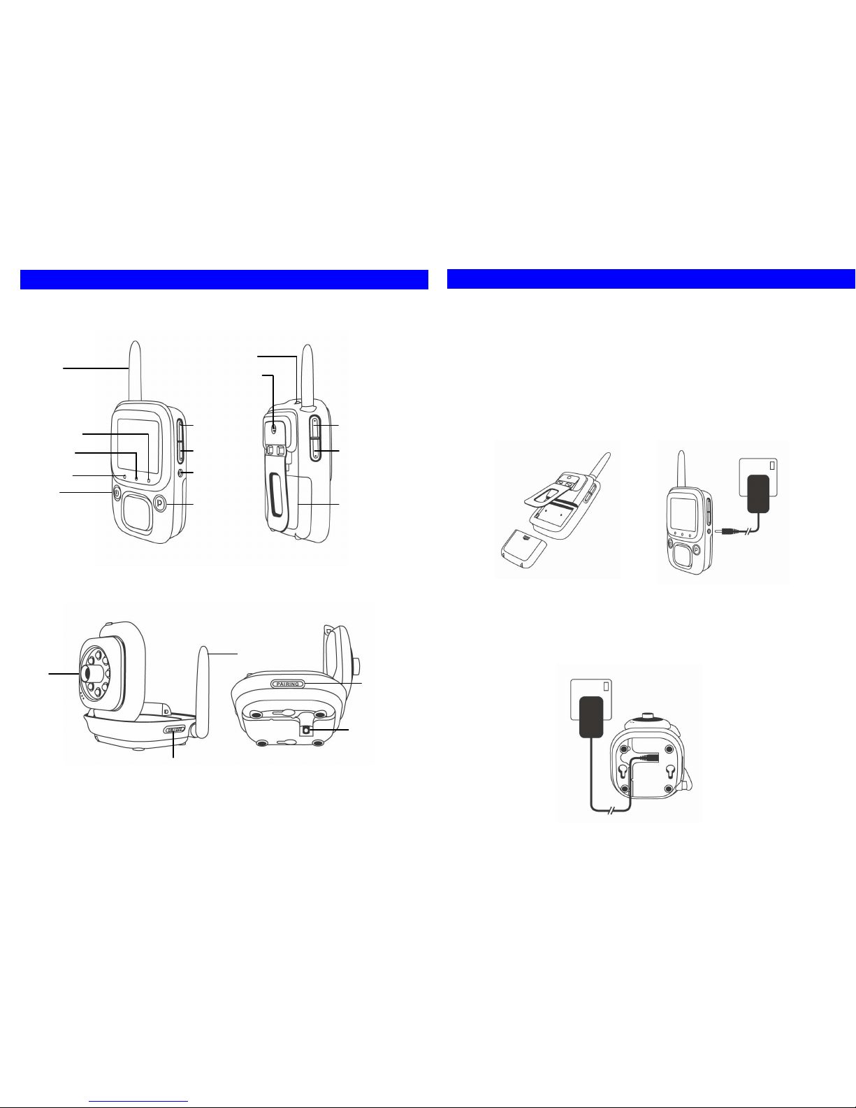
2. Part List
A. Monitor Unit
B. Camera Unit
Antenna
Chargue LED
Signal LED
Power LED
Power
Strape Holder
Belt Clip/ Stand
Volume Up
Volume Down
A/C Adaptador
Jack
Pairing
Brightness
Up
Brightness
Down
Battery
Cover
A/C Adaptador
Jack
Power
Pairing
Antenna
Lens
3
3. Installation
A. Monitor Unit Installation
1. As shown in pic. 1, lift the Belt Clip at the back of Monitor Unit, and remove the
battery door.
2. Insert the Lithium battery in correct direction. Make sure the metal contact of battery
is in touch with the metal contact of battery bay.
3. Close the battery door.
4. Charge the battery by using the provided AC adapter. Attach the AC adapter to the
Monitor Unit as shown in pic. 2. Then plug the AC adapter into the wall AC socket.
5. The battery charging process will start automatically (Charge LED on). For first time
usage, please keep charging the battery for at least 3 hours until the charge LED
goes off.
6. Press power button to power on the Monitor Unit.
B. Camera Unit Installation
1. Attached the provided AC adapter to the Camera Unit as shown in pic 3. The power
jack is located at the bottom of the Camera Unit. Plug the AC adapter into the wall
AC socket.
2. Press ‘Power Button’ to power on the Camera Unit.
Pic 2
A/C
Adaptador
Wall Outlet
Pic 1
Pic 3
A/C
Adaptador
Wall Outlet
 Loading...