

Page 1

LC-22C
March, 2000
MF-9010 INSTRUCTION MANUAL
Temperature Controllers
Bioanalytical
Systems, Inc
2701 Kent Avenue
West Lafayette
Indiana 47906
for Liquid Chromatography
Page 2

MANUFACTURER’S NOTE
The BAS logois a registered trademarkof Bioanalytical Systems, Inc.
Copyright March 2000
No portion of this manual may be reproduced without express, written permissionof Bioanalytical Systems, Inc.
ALL RIGHTS RESERVED
Bioanalytical Systems, Inc.
2701 Kent Avenue
West Lafayette, IN USA 47906-1382
Phone: (765) 463-4527
Fax: (765) 497-1102
Page 3
Section 1. PREFACE
Section 1. PREFACE
The Bioanalytical Systems LC-22CTemperature Controller andLC-23A and LC-23C
Column Heating Compartments are versatile tools for the experimenter who desires precise,
reproducible temperature control for liquidchromatography.
The LC-22C DualChannel Temperature Controller is a general purposeinstrument capable
of regulating two independentdevices, such as heatingmantles, heat tapes, electrochemical
cell preheaters, and column heating blocks. The temperature control point isset with a
multi-turn front-panel potentiometer and thepower applied to the heating unit is regulated
by a temperaturesensor located in thedevice being controlled. In heating devices of BAS
manufacture, the temperature sensoris built into theinstrument. To control other devices, a
universal probe (part no. EW-8116) is available forseparate purchase.
The LC-23A ColumnHeating Compartment is usedin conjunction with the LC-22C. This
instrument is simple in design and extremelydurable. It accepts most commercially
available 15, 25 or 30 cm analyticalcolumns. Asolid aluminum inner compartment,
thermally isolated from the outer cover,encloses the entire column. A preheatercoil is
included with each unit. The LC-23A can, in someinstances, be altered toaccommodate
wider diameter columns. This alteration would involvean additional charge for
customization. Ifyou require modifications, please contact BAS customer service for a
quotation.
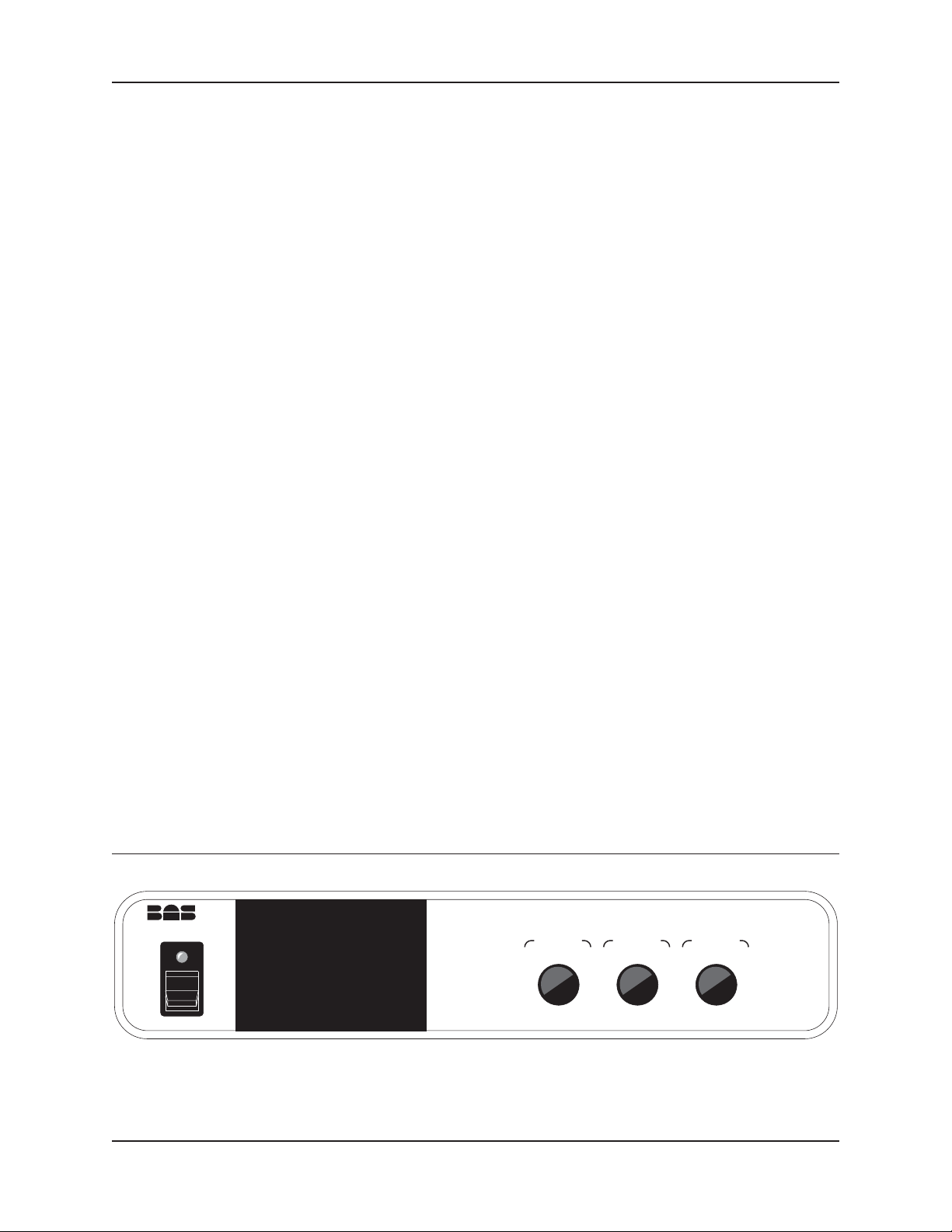
Figure 1. LC-22C Front Panel.
Temperature Controller
The LC-23C CartridgeColumn Heating Compartment accommodates two cartridge format
columns up to15cm in length. The LC-23C canbe mounted within the BAS CC-5
Chromatography Compartment, which ispart of the BAS 480 Liquid Chromatographsand
LC-44 Electrochemical Detectors. The LC-23C is also sold with orwithout the CC-5, the
latter as anupgrade to existing BASdetectors or BAS 480 systems.
The Cell Preheateroption for BAS electrochemicaldetectorsis also controlled byan
LC-22C. Thepreheater coil can accommodatethe heating of stainlesssteel tubing between
the column andcell inlet.
LC-22C
DISPLAY
SELECT
SETPOINT
HEATER 1
SETPOINT
HEATER 2
1
Page 4
Section 2. POWER REQUIREMENTS LC-22C CONTROLLER
Section 2. POWER REQUIREMENTS
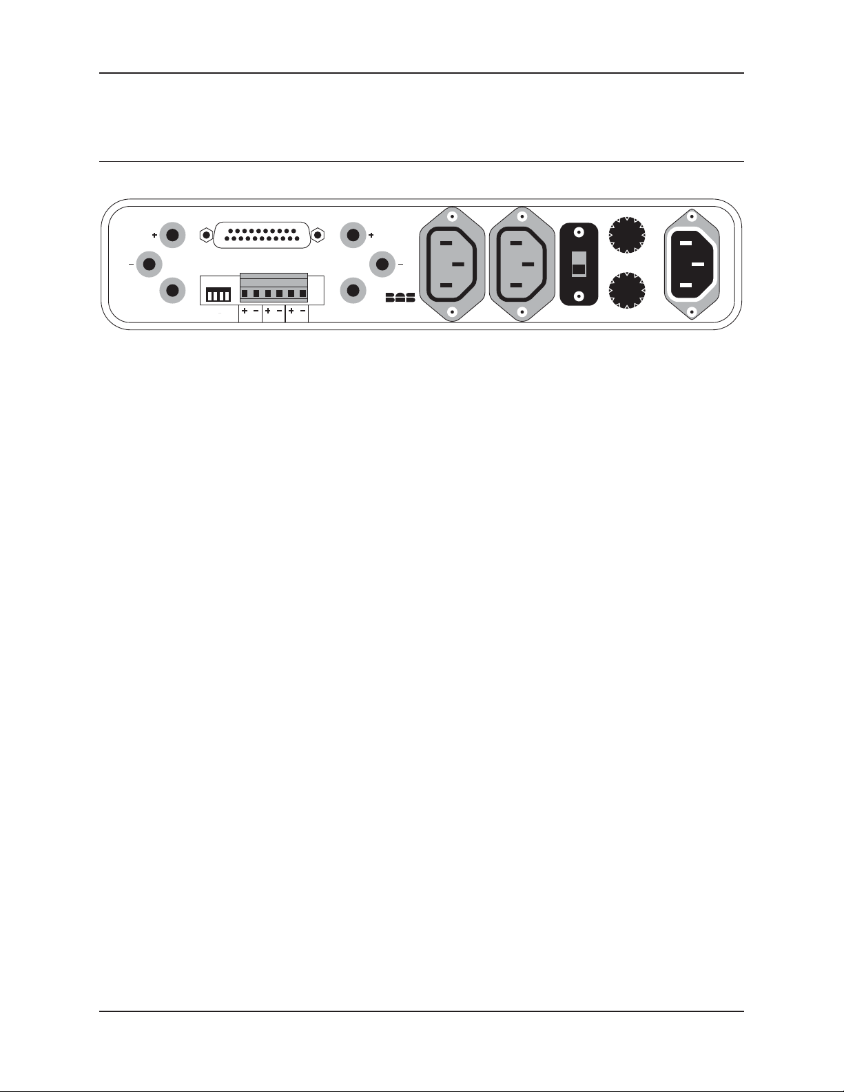
Figure 2. LC-22C Back Panel.
REMOTE
PROBE 1 PROBE 2
ADDRESS OUTPUT
GND
1234
21INH
GND
LC-22C
Made in USA
HTR 2HTR 1 F1
F2
LC-22C CONTROLLER This instrument can be operated from either115V/50-60Hz or 230V/50-60Hz. The line
voltage selector for 115V or 230V operationis on the back chassis panel. The line voltage
must be selectedbefore applying power to the controller.
A 3-prong powercable on the LC-22C must be connectedto a standard, groundedpower
outlet for safety. Ifthe instrument is operatedfrom a poweroutlet without a ground
connection, an appropriate adapter should be used andthe ground connection of this
adapter should be securelyfastened to an earth ground.
LC-23A and LC-23C HEATING COMPARTMENTS
The LC-23A andLC-23C compartments are designedspecificallyfor use withthe LC-22C
Controller. Two cables (one for heater powerand the other for the temperature sensor)
connect to the LC-22C to each heatingdevice. If you havepurchased a heating
compartment for use with an older model LC-22A, you may be unable to make the
connection directly to thecontroller without an additional adapter. A change indesign
converted this from a 3-prong male plugto the current female plug. The adapter (EF-1575)
is available from BAS at an additionalcharge.
2
Page 5

LC-22C CONTROLLER Section 3. INSTALLATION
Section 3. INSTALLATION
LC-22C CONTROLLER This section concerns installation forstand-alone operation of the LC-22C with the optional
universal probe. For operationof the other accessories,see subsequent sections.
1. Use the cableadapter (EF-1575) to convertthe special safety receptacle onthe back panel
of the LC-22Cto a standard 3-prong socket. Plug the deviceto be controlled (e.g.,
heating mantle, tape, etc.)into this socket. If you only wish to measure temperature
and do notneed to control it, you can skipthis step.
2. Plug the cableleads from the stainlesssteel UNIVERSAL PROBE (EW-8116)into the
red, yellow, and black jackson the backpanel of the LC-22C labeled “PROBE 1"or
”PROBE 2". The black jackprovides grounding for the instrument and must be
connected for safety purposes.
3. The liquid probe is usually accurate to within 1°C of theactual set-point when shipped.
The reproducibility or precisionof the temperature set-point is± 0.1°C regardlessof
the actual temperature. Ifgreater accuracy is desired,follow the calibration procedure.
To performthe calibration, first remove the top cover of the LC-22C byremoving the
four screws located on the sides ofthe top cover. Since both channel1 and channel 2
are identical, calibrating instructions willbe given for channel1 adjustments, while
channel 2 adjustments willappear in parentheses ().
To calibratethe probe, place itin an ice bath and connect theprobe leads to the
“PROBE 1" (”PROBE 2") jacks on the back panel. Turn the main poweron and rotate
the display selector knobto “SENS 1"(”SENS 2"). Usinga small screwdriver, rotate
the adjusting screw on the top ofthe potentiometer R45 (R56) for a readingof 00.0°
on the front-panel digitalreadout. Remove the probe from the ice bath. If a two-point
calibration is desired, goto step 5.
4. This completes the single-pointcalibrationof the liquid probe. The top cover should be
reinstalled using the fourretaining screws on thesides of the cover.
5. A two-point calibration canbe made byplacing the probe inboiling water and adjusting
R46 (R55) firstto a display readingof 99.9, then to 00.0 (indicating 100.0°C) withthe
center decimal point on. There could be a very slight interaction between thefreezing
and boiling point adjustments,so additional adjustments to R45and R46 (R56and
R55) could beneeded to obtain thehighest degree of accuracy. Remove theprobe
from the hightemperature bath.
6. This completes the two-pointcalibration of the liquidprobe. The top cover should be
reinstalled using the fourretaining screws on thesides of the cover.
3
Page 6
Section 3. INSTALLATION LC-23A COLUMN HEATING COMPARTMENT
LC-23A COLUMN HEATING
COMPARTMENT
1. Place the LC-23Aheating Compartment in thedesired location. Six holes withcaptive
6-32 threads are provided for secure mountingon your liquid chromatograph,if
desired. The holes are positioned to fit earlymodel (pre 1986) BAS liquid
chromatography support stands.
2. Connect the LC-23A heater power cable tothe power socket on the back panelof the
LC-22C Controller.
3. Connect the red, black and yellow plugson the probe cableto the jacks marked “PROBE
1" or ”PROBE 2" on the LC-22C back panel.
4. Remove the coveron the LC-23A Column Heater by unscrewingthe two cap screws.
Place the columnin the recessed cavityand route the inletand outlet tubing outof the
top and bottomslots. A special preheater block(EW-8146) is also supplied. Under
certain circumstances, dramatic bandbroadeningmay result ifthe preheater is not
utilized. Typically thisbecomes obvious when the temperature differential between
ambient and thedesired set point exceeds20-25°C.
If you planto use several differentstyles of column endfittings, itis best to use
removable plastic fittings. BAS recommends a 2-piece PEEK finger-tightseal as
provided in BAS part no. MR-4409 (this includes a nut and ferrule). One pieceplastic
fittings tend to loosenat higher temperatures.
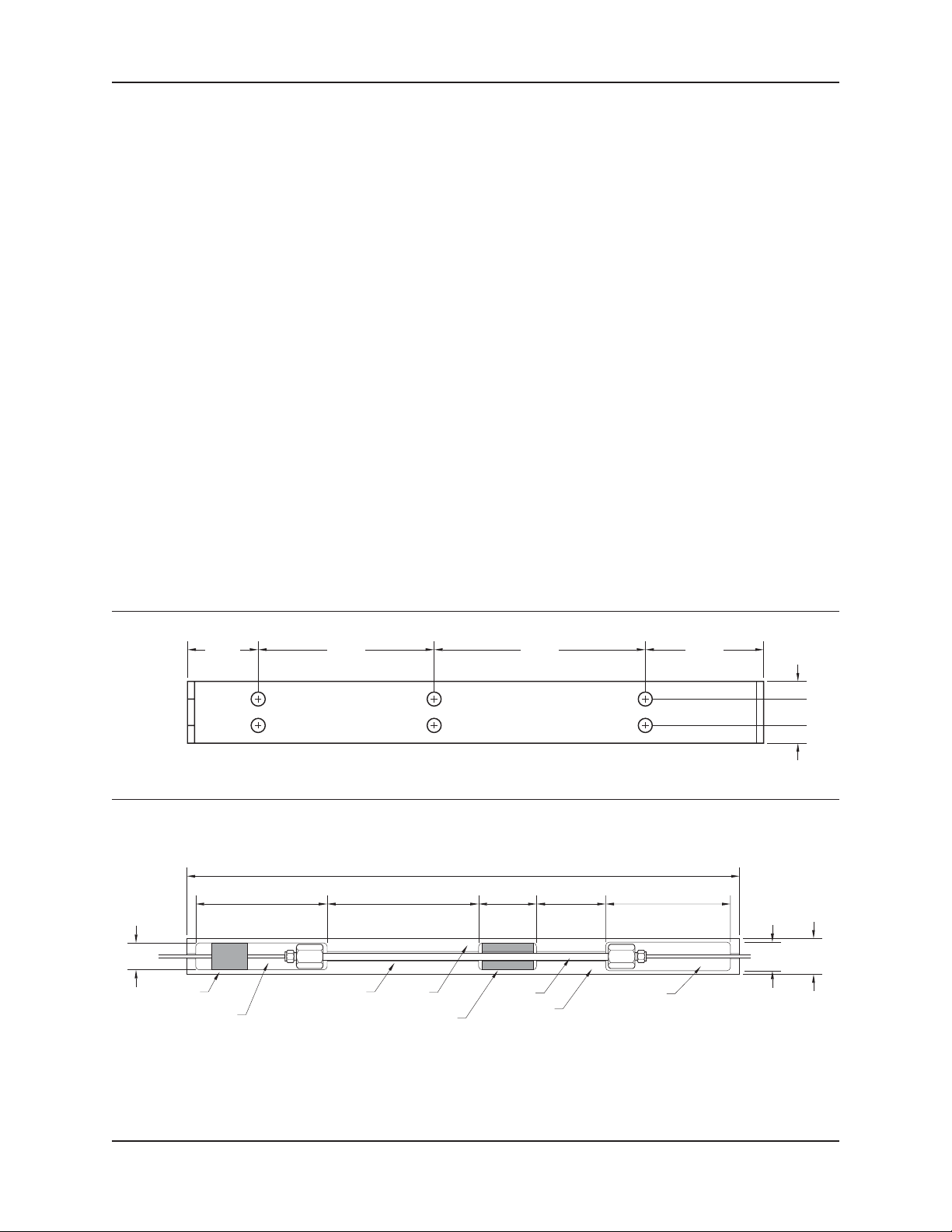
Figure 3. Position of Mounting Points on LC-23A Heater.
2.01 5.00 6.00 3.37
Figure 4. LC-23A Column Heater with LC-23PH Preheater Installation.
39.37cm
10.79cm
SENSOR
LOCATION
ADAPTER FOR
25-30cm COLUMNS
4.12cm
COLUMN
1.93cm
PREHEATER
1.91 x 2.54cm
INLET DEPTH
1.89cm
9.36cm
CHANNEL WIDTH
0.685cm
HEATER
BLOCK
4.92cm
8.89cm
OUTLET DEPTH
1.85cm
2.03cm
0.50
0.75
0.50
2.54cm
4
Page 7
LC-23C COLUMN HEATING COMPARTMENT Section 3. INSTALLATION
LC-23C COLUMN HEATING
COMPARTMENT
The LC-23C isspecifically designed to fit withinthe BAS CC-5Column Compartment. The
CC-5 is pre-drilled to accept a Rheodyneinjectionvalve on the front panel. It has several
grooves on bothsides for convenient access to external detectors.
If you areinstalling the LC-23C asan upgrade to a BAS electrochemical detector or BAS
480 Liquid Chromatograph, andalready have a cell preheater installed in theCC-5, you
may wish to remove it. Routing thetubing from the LC-23C to the cellpreheater and then
to the detectoris difficult due to space limitations. The LC-23C alonewill provide
satisfactory temperature control forthe electrochemical cell if you keep the coverclosed
during operation.
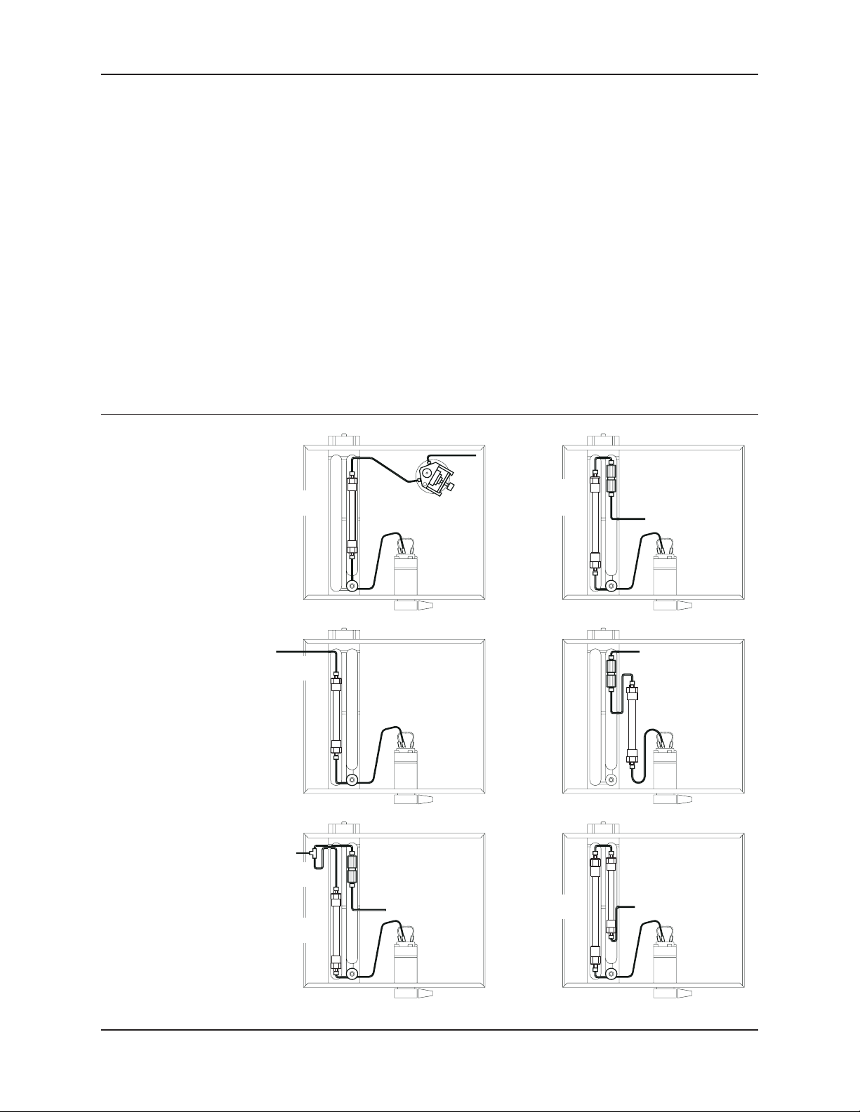
Before installing the LC-23C,give some thought to the configurations of the column(s) you
intend to use. Some configuration using compact BAS cartridge columnsare diagrammed
in Figure 5. You can alsoleave the analytical column outsidethe LC-23C (at room
temperature) and heat a post-column reactor (tubing coil,packed bed) within theLC-23C.
Figure 5. Combinations of Column Formats Within the LC-23C.
10cm
ANALYTICAL
COLUMN
15 OR 10cm
ANALYTICAL
COLUMN
3cm
POST-COLUMN
TO UV
DETECTOR
MIXING TEE
AND REAGENTS
ANALYTICAL
COLUMN
POST-COLUMN
REACTOR
15cm
ANALYTICAL
COLUMN
POST-COLUMN
REACTOR
ANALYTICAL
COLUMN AT
AMBIENT
10cm
ANALYTICAL
COLUMN
5
Page 8
Section 3. INSTALLATION LC-23CCOLUMNHEATING COMPARTMENT
Installing the LC-23C in a CC-5 Compartment
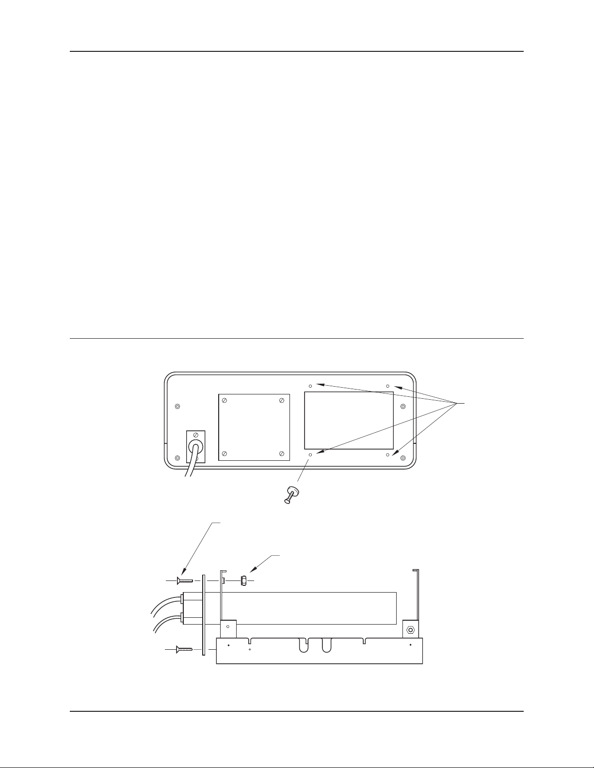
1. Lower the CC-5lid and remove the utility cover from the back panel of the CC-5 cabinet
(four screws).
2. On some models,pressed-in, threaded nuts will be located on theoutside of the back
panel (Figure 6). These must be removed. DO NOT REMOVE IFTHEY ARE ONTHE
INSIDE OF THECABINET. To remove external nuts,screw a long machinescrew (6-32
thread) into the nut from the rear until it protrudes throughthe nut. Use pliersfor
leverage and gently work the screw fromside to side until the nut comesloose.
3. Remove the LC-23Ccover and set aside. Push the heater block throughthe now open
utility access in the CC-5 back panel. On some models, the two registrationposts on
the CC-5 innerpanel will engage theLC-23C block for support.
4. Secure the LC-23Cto the cabinet usingfour 6-32 x 1/2" machine screws andfour 6-32
lock nuts. The lock nuts are notnecessary if pressed-in nutsare available on the inside of
the CC-5 cabinet. The mountingplate should now beflush with the outsideof the back
panel on theCC-5 cabinet.
Figure 6. Installation of the LC-23C in a BAS 480 or CC-5 Electrochemical Detector. (A) Location of four screws (B) Breaking off
the pressed-in nuts (C) Left Side View of Attachment Hardware.
A
SCREW
LOCATIONS
B.
6-32 x 1/2" SCREW
(4 PLACES)
CC-5
REAR
6-32 LOCKNUT
(4 PLACES)
C.
CC-5
FRONT
6
Page 9
LC-23C COLUMN HEATING COMPARTMENT Section 3. INSTALLATION
Making Plumbing Connections
For simple arrangements, use the innermost trough of the LC-23C. This locationminimizes
detector and valve hookup tubing. If you are coupling columns together,the longer trough
will be moreuseful.
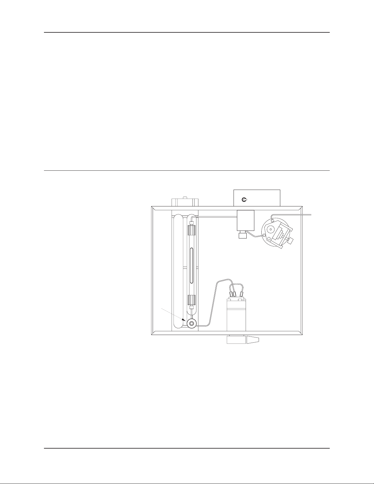
A special coilof tubing is providedwith each LC-23C (see Figure 7). At your option, it may
be installed between theinjection valve and column. The coilfunctions as a mobile phase
preheater, so that large temperature gradients atthe head of the column are minimized. The
coil may beremoved by unscrewing thecentral cap screw (5/32" hex).
It is advisable not to use apermanent ferrule on the outlet end of the preheater coil. A
removable high-pressure fitting provides an equivalent seal without irreversible attachment.
Use BAS part no. MR-4409.
Figure 7. Column Preheater Coil Installed in LC-23C. This Unit is Part of a BAS 480 Liquid Chromatography System with the
Electrochemical Cell and Cell Preheater Options Installed.
PREHEATER POWER
HIGHLOW
Leaks
Make sure thatall fittings are leak-tight atthe usual operating pressurebefore mounting the
insulating top cover.
Insulating Top Cover
The U-shaped top cover is insulated on three sides with a foam polymer. The cover is
asymmetric; the notch in the cover goesalong the right side. Mount the cover at therear
first and thendrop the front inplace.
7
Page 10

Section 4. OPERATION TEMPERATURE MEASUREMENT/CONTROL MODE
Section 4. OPERATION
For purposes ofinstruction,we will reference channel1, although channel 2is identical.
1. With the heaterand probe cables disconnected, turnon the main power to the LC-22C.
2. Rotate the display selectorknob to illuminate “SET1" in the red display window.
3. Using the “SETPOINTHEATER 1" knob, select the desiredtemperature, which is between
ambient and 99.9°C.
4. Turn offthe main power to the LC-22C and connect the heater to “HTR-1" and thered,
yellow and black probe plugs to thesame color jacks of ”PROBE-1" on the back panel.
5. Turn onthe main powerto the LC-22C. The heater indicator LED will remain constantly
illuminated until the setpoint is reached, thenit will dim or blink intermittently to
indicate maintenance at thedesired temperature. You can also observe the measured
probe temperature by changingthe display select switchto “SENS 1".
TEMPERATURE MEASUREMENT/CONTROL MODE
LC-23A or LC-23C Column Heaters
and Electrochemical Cell Preheater
1. Ensure that the three (3) leads from the column heatersor cell preheater areplugged into
the jacks marked“PROBE 1" or”PROBE 2"
2. Turn onthe LC-22C. Set the desired temperature (at least 5°C above ambient).
3. The measured temperature can be read onthe front panel digitaldisplay of the LC-22Cby
using the display selectorknob. The temperature isalso available as an analog voltage
at the screwterminals marked “OUTPUT + 1 -” or “OUTPUT + 2 -”, depending upon
the channel used. Each 100 mV (0.1 volt) is equivalent to1°C. For example:
+8.92 volts = +89.2°C
-0.36 volts = - 3.6°C
This voltage may be recorded using a strip chart recorder. Set the fullscale input of
the recorder to10 volts and observe the marked polarityon the back panel.
4. The LED lightwill stay on continuously untilthe heater achieves thesetpoint and then will
flash intermittently while maintaining thistemperature. The actual temperature (within
the absolute accuracy ofthe probe) atany point in time will be displayed on the front
panel digital display ofthe LC-22C or the recording device.
8
Page 11

TEMPERATURE MEASUREMENT/CONTROL MODE Section 4. OPERATION
Universal Liquid Probe
1. Ensure that the stainlesssteel probe is pluggedinto the jacks marked “PROBE 1" or
”PROBE 2" and observe the colorcode used on the jacks.
2. Turn themain power on to the LC-22C. Rotate the displayselector knob to “SENS 1"
or ”SENS 2", depending upon which channelis being used for measurement. The
digital display will readthe probe temperature in degrees C.
3. The measured temperatureis available as an analog voltage at the “OUTPUT” screw
terminals on the back panel. This six positionterminal strip is detachable:pull straight
back for release. Probe 1 outputs are the labeled “+ 1 -”,probe 2 outputsare labeled
“+ 2 -” on the backpanel.
4. An analog voltage of 100 mV (0.1 volt) is equivalent to 1°C. For example:
+8.92 volts = +89.2°C
-0.36 volts = - 3.6°C
This voltage may be recorded using a strip chart recorder. Set the fullscale input of the
recorder to 10volts. Observe the marked polarity.
5. To controlthe temperature while measuringit, first turn offthe main power to the LC-22C.
Connect the power cable of the heatingdevice (75 watts maximum)to the appropriate
heater jack, i.e., “HTR 1" if ”PROBE 1" is the corresponding sensor channel.
Turn themain power on and select the correspondingchannel setpoint LED. Rotate the
setpoint heater knob to obtain the desired controltemperature. The actual probe
temperature can be observed by changing the display selector knob tothe controlled
channel’s sensorLED, marked “SENS1" or ”SENS2".
9
Page 12

Section 5. SAFETY AND MAINTENANCE CHECKS
Section 5. SAFETY AND MAINTENANCE CHECKS
The LC-22C, LC-23A,LC-23C and cell preheaterare all essentially maintenance free
instruments. BAS does advise that you attempt to keep these piecesin good condition by
following these suggestions:
1. Avoid corrosive laboratory environments.
2. Don’t stack heavy items on signal cablesor allow them to become crimped duringuse
or storage.
3. Clean up spills insidecolumn heaters immediately.
4. Avoid contact of organicsolvents with the insulating materialinside the LC-23C cover.
The Universal Probe is based on a reliable solid state devicecapable of generating a
predictable current related tothe temperature of itsenvironment. To checkthe integrity of
this probe, apply the following test:
1. Expose probe to ambient temperature and disconnect anyheating devices from the
LC-22C.
2. Turn onthe LC-22C power.
3. Set the temperaturesetpoint to a valuegreater than ambient (allowat least 1°C difference).
The “HTR” LED indicator on the LC-22C should be on continuously.
4. An open circuitanywhere in the probe,cable or across its input jacks will automatically
shut down theheater circuit. This feature was incorporated to protect againstthermal
“runaway” and should be tested periodically. Perform the following check:
A. Plugin the probe, exposeto ambient air temperatureand turn on the
power to theLC-22C.
B. Createan open circuit inthe probe by unplugingthe red or yellow lead
from the chassisjacks on the LC-22C. Using the digital display
selector knob, illuminate thetested channel “SENS 1"or ”SENS 2"
LED. A digital readingof approximately .3.9.8 degrees (-13.98 volts at
the OUTPUT screwterminals) will be shown. Note that the left, center
and right decimalpoints are illuminated indicating an open circuit.
10
C. Remove the probe entirely andplace a jumper cable across the redand
yellow PROBE INPUTjacks to create a closed circuit. A digitalreading
of approximately 2.7.9 degrees(+12.79 volts at theOUTPUT screw
Page 13

Section 5. SAFETY AND MAINTENANCE CHECKS
terminals) will be shown. Note that the center and right decimalpoints
are illuminated indicating a closed circuit.
If your unitfails either step 3or 4, pleasecontact the BAS Service Coordinator to return
both the LC-22Cand the probe used to make thesetests for service. Do not return any
equipment without first obtaining a Return Authorization number from BAS.
11
Page 14

Section 6. SPECIFICATIONS
Section 6. SPECIFICATIONS
Temperature Setpoint
Temperature Measurement
Readout
Max. Load
Repeatability
Output TemperatureCalibration
0.00°C to 99.9°C in 0.1°C increments
-50°C to 115°C
Front panel LED
75 watts, eachchannel
0.1°C with thesame temperature probe.
Output is calibrated to100 mV per °C.
Rear Panel
Probe input jacks, outputtemperature jack,
output power socket heaters,line voltage selector.
Heater Power
Heater power iscontrolled by zero crossing,
solid state relays for noise-free operation.
Fuses
For 115V,2A Slo Blow,
For 230V,1A Slo Blow
12
 Loading...