

Page 1

MC6040-5 / MC6040-8 / MC6040-10 /
HC6040-5 / HC6040-8 / HC6040-10
117900 - 117901 - 117902
117905 - 117906 - 117907
Page 2

Bartscher GmbH
Franz-Kleine-Str. 28
D-33154 Salzkotten
Germany
Phone: +49 5258 971-0
Fax: +49 5258 971-120
Technical Support Hotline: +49 5258 971-197
www.bartscher.com
Version: 1.0
Date of preparation: 2022-09-05
EN
2
Page 3

Original instruction manual
1 Safety ............................................................................................................ 2
1.1 Explanation of Signal Words .................................................................... 2
1.2 Safety instructions.................................................................................... 4
1.3 Intended Use ........................................................................................... 7
1.4 Unintended Use ....................................................................................... 7
2 General information ....................................................................................... 8
2.1 Liability and Warranty .............................................................................. 8
2.2 Copyright Protection ................................................................................ 8
2.3 Declaration of Conformity ........................................................................ 8
3 Transport, Packaging and Storage ................................................................ 9
3.1 Delivery Check ......................................................................................... 9
3.2 Packaging ................................................................................................ 9
3.3 Storage .................................................................................................... 9
4 Technical Data ............................................................................................. 10
4.1 Technical Specifications ........................................................................ 10
4.2 List of Components of the Appliance ..................................................... 20
4.3 Functions of the Appliance ..................................................................... 23
5 Installation Instructions ................................................................................ 23
5.1 Unpacking and Positioning .................................................................... 24
5.2 Electrical Connection ................................ ............................................. 27
5.3 Water Connection .................................................................................. 28
5.4 Connection of Condensation Hood ........................................................ 30
6 Operating Instruction ................................................................................... 32
6.1 Operation ............................................................................................... 34
6.2 Settings ................................................................ ................................ .. 67
7 Cleaning and Maintenance .......................................................................... 78
7.1 Safety Instructions for Cleaning ............................................................. 78
7.2 Cleaning ................................................................................................. 79
7.3 Maintenance .......................................................................................... 84
8 Disposal ....................................................................................................... 86
117900 1 / 86
Page 4
Safety
EN
Read this instruction manual before using and keep it available
at all times!
DANGER!
The signal word DANGER warns against hazards that lead to severe
injuries or death if the hazards are not avoided.
Diese Bedienungsanleitung beschreibt di e Installation, Bedienung und Wartung d es Geräts und gilt als wichtige Infor mationsquelle und Nachschlagewerk. Die Kenntnis aller enthaltenen Sicherheits hinweise und Handlungsanweisunge n schafft die Voraussetzung für das sich ere und sachgerechte Arbeiten mit d em Gerät. Darüber hinaus müssen die f ür den Einsatzbereich des Geräts gelt enden örtlichen Unfallverhütungsvorsc hriften und allgemeinen Sicherheitsb estimmungen eingehalten werden. Dies e Bedienungsanleitung ist Bestandteil d es Produkts und muss in unmittelb arer Nähe des Geräts für das In¬stallations -, Bedienungs-, Wartungs- und R einigungspersonal jederzeit zugängli ch auf¬bewahrt werden. Wenn das Gerät a n eine dritte Person
weitergegeben wird, muss die Bedienungsa nleitung mit ausgehändigt werden.
This instruction manual contains information about installation, operation and
maintenance of the appliance and constitutes an important source of information
and reference guide. The knowledge of all operational and safety instructions
included in this manual is a prerequisite for safe and proper handling of the
appliance. Additionally, accident prevention, occupational health and safety, and
legal regulations in force in the area the appliance is used apply.
Before you start using the appliance, especially before turning it on, read this
instruction manual in order to avoid personal injuries and property damages.
Improper use may cause damage.
This instruction manual forms and integral part of the product and must be stored in
an immediate vicinity of the appliance and be available at all times. The instruction
manual should be transferred together with the appliance.
1 Safety
This appliance has been manufactured in accordance with technical standards
currently in force. However, the appliance may be a source of hazards if used
improperly or contrary to its intended purpose. All persons using the appliance must
consider information included in this instruction manual and observe safety
instructions.
1.1 Explanation of Signal Words
Important safety instructions and warning information are indicated in this
instruction manual with appropriate signal words. You must strictly follow the
instructions, to prevent accidents, personal injuries and property damages.
2 / 86 117900
Page 5

Safety
EN
WARNING!
The signal word WARNING warns against hazards that may lead to
moderate or severe injuries or death if the hazards are not avoided.
CAUTION!
The signal word CAUTION warns against hazards that may lead to
light or moderate injuries if the hazards are not avoided.
IMPORTANT!
The signal word IMPORTANT indicates possible property damages,
which may occur if safety instructions are not observed.
NOTE!
The symbol NOTE indicates subsequent information and guidelines
for the user on usage of the appliance.
DANGEROUS VOLTAGE
Dangerous voltage inside. Contact leads to electric shock or burns.
Before performing maintenance and cleaning works, the system
must be switched off and locked.
Failure to observe these instructions may result in serious injury.
RISK OF BURNS!
This symbol indicates situations where persons must be careful not
to touch any hot external surfaces of the oven during operation.
Failure to observe these instructions may result in serious injury.
RISK OF BURNS — hot water and steam!
This symbol indicates situations in which persons must take care
not to come into contact with hot water on surfaces and steam
which may be generated when the oven is in operation.
Failure to observe these instructions may result in serious injury.
RISK OF BURNS — hot steam!
, die
Warning Signs on the Appliance
117900 3 / 86
Page 6

Safety
EN
This symbol indicates situations in which persons must take care
not to come into contact with hot steam which may escape during
the operation of the oven.
Failure to observe these instructions may result in serious injury.
RISK OF BURNS — handling hot sheets with products!
This symbol indicates situations where persons must be careful
when handling hot sheets with hot products and liquids that may fall
or spill on a person during loading or unloading. The sticker is part
of the scope of supply of the appliance and must be placed at a
height of 1.6 m above the installation surface.
Failure to observe these instructions may result in serious injury.
1.2 Safety instructions
Electrical Current
• Too high a mains voltage or incorrect installation may cause electric shock.
• The appliance may be connected only if data on the rating plate correspond with
the mains voltage.
• To avoid short-circuit, the appliance should be kept dry.
• If there are malfunctions during operation, disconnect the appliance from the
power supply.
• Do not touch the appliance’s plug with wet hands.
• Never take hold of the appliance if it has fallen into water. Immediately
disconnect the appliance from the power supply.
• Any repairs or housing opening may be carried out by professionals and
relevant workshops only.
• Do not transport the appliance, holding it by the power cord.
• Do not allow the power cord to come into contact with heat sources or sharp
edges.
• Do not bend, pinch nor knot the power cord.
• Always completely unwind the power cord.
• Never place the appliance or other objects on the power cord.
• Always take hold of the plug to disconnect the appliance from the power supply.
• Check the power cord regularly for damage. Do not use the appliance if the
power cord is damaged. If this cable is damaged, it must be replaced by
customer service or a qualified electrician in order to avoid dangers.
4 / 86 117900
Page 7

Safety
EN
Flammable Materials
• Never subject the appliance to contact with high temperature sources, e.g.:
oven, furnace, open flame, heat generating devices, etc.
• To avoid fire hazard, clean the appliance regularly.
• Do not cover the appliance with, e.g., aluminium foil or cloths.
• Use the appliance only with materials designated to this end and with correct
temperature settings. Materials, groceries and left-overs remaining in the
appliance may catch fire.
• Never use the appliance near flammable or inflammable materials, e.g.: petrol,
spirit, alcohol, etc. High temperature triggers evaporation of these materials,
and, as a result of contact with sources of ignition, an explosion may occur.
• In case of fire, disconnect the appliance from the power supply before
attempting suitable fire-extinguishing actions.
• Never attempt to extinguish fire with water if the appliance is connected to the
power supply. Following extinction of fire, ensure sufficient fresh air inflow.
Hot Surfaces
• Surfaces of the appliance become hot during operation. Burning hazard! High
temperature remains for some time after switching the appliance off.
• Do not touch any hot surfaces of the appliance. Use the provided handling
elements and holders.
• You may transport and clean the appliance after it cools down entirely.
• It is prohibited to sprinkle hot surfaces with cold water or flammable liquids.
Operating Personnel
• The appliance may only be operated by qualified personnel and trained
specialist personnel.
• This appliance may not be operated by persons (including children) with limited
physical, sensory or mental capabilities, nor by persons with limited experience
and/or limited knowledge.
• Children should be supervised to ensure that they are not playing with or
switching on the appliance.
Supervised Usage only
• Only supervised appliance may be used.
• Always remain in an immediate vicinity of the appliance.
117900 5 / 86
Page 8

Safety
EN
Improper Use
• Unintended or prohibited use may cause damage to the appliance.
• The appliance may only be used when its technical condition is flawless and
allows for safe operation.
• The appliance may only be used when all connections are executed according
to rules of law in force.
• The appliance may only be used when it is clean.
• Use only original spare parts. Never attempt to repair the appliance on your own.
• Do not introduce any changes in the appliance nor modify it.
6 / 86 117900
Page 9

Safety
EN
1.3 Intended Use
As described below, every use of the appliance for a purpose differing and/or
diverging from its intended standard use, is prohibited and considered to be an
unintended use.
The following is an intended use:
– Baking bread
– Baking cakes
– Preparation of suitable food products
1.4 Unintended Use
An unintended use may lead to personal injuries or property damages caused by
hazardous voltage, fire or high temperature. The appliance may only be used to
perform tasks described in this instruction manual.
The following is an unintended use:
– Processing of unsuitable food products
– Heating of rooms
– Drying clothes
– Storage of flammable objects
– Heating up and warming up of liquids and materials that are flammable,
hazardous to health, volatile, etc.
117900 7 / 86
Page 10

General information
EN
2 General information
2.1 Liability and Warranty
All information and instructions in this instruction manual account for legal
regulations in force, current level of technical engineering knowledge as well as our
expertise and experience, developed over the years. If special models or additional
options are ordered, or state-of-the-art technical solutions were implemented, the
actual scope of delivery of the appliance may, in some circumstances, differ from
descriptions and numerous drawings in this instruction manual.
The manufacturer is not liable for any damages nor faults stemming from:
– failure to observe instructions,
– unintended use,
– technical alterations introduced by the user,
– usage of unapproved spare parts.
We reserve the right to introduce technical modifications to the product, intended for
improvement of the appliance and its performance.
2.2 Copyright Protection
This instruction manual, and texts, drawings and images included in it, as well as its
other components are copyright protected. It is prohibited to reproduce this
instruction manual (including its excerpts), in any form and by any means, and to
use and/or transfer its content to third parties without manufacturer’s written
permission. Violation of the above results in obligation to pay compensation. We
reserve the right to claim further damages.
2.3 Declaration of Conformity
The appliance meets the currently applicable standards and guidelines of the
European Union. We confirm the above in the EC Declaration of Conformity. We
may provide relevant Declaration of Conformity upon request.
8 / 86 117900
Page 11

Transport, Packaging and Storage
EN
3 Transport, Packaging and Storage
3.1 Delivery Check
Immediately upon reception, check the delivery for completeness and possible
shipping damage. In the case of visible transport damage refuse to accept the
appliance or accept it conditionally. Mark and note the scope of damage in shipping
documents/consignment list of the shipping company and lodge a complaint.
Concealed damage must be reported immediately upon its discovery, as
compensation claims may only be filed within applicable time limits.
If you find that parts or accessories missing, please contact our Customer Service
Department.
3.2 Packaging
Do not dispose of the appliance cardboard box. It may be used to store the
appliance when relocating or when shipping the appliance to our service point in the
case of any damages.
The packaging and its elements are made of recyclable materials. Particularly,
these are: plastic films and bags, cardboard box.
When disposing of the packaging, observe applicable domestic regulations.
Recyclable packaging materials should be recycled.
3.3 Storage
Leave the packaging closed until installation of the appliance; observe external
indications concerning method of placing and storage. Store the packaging in the
following conditions only:
– in closed rooms;
– in dry and dust-free surrounding;
– away from aggressive agents;
– in a location protected against sunlight;
– in a location protected against mechanical shocks.
In the case of extended storage (over three months), make sure you check the
condition of the packaging and the parts regularly. If needed, replace the packaging
with a new one.
117900 9 / 86
Page 12

Technical Data
EN
4 Technical Data
4.1 Technical Specifications
General Description of Appliances
The ovens are designed to process food by means of uniform circulation of hot air
in the oven chamber, with the possibility of using steam. Food must always be
placed on standard EN 60/40 baking sheets or grates, which are then placed on
guide rails.
Ovens must always be installed on a base. The bases offered by the manufacturer
must be ordered separately.
Three standard sizes of convection ovens are available:
Convection ovens HC6040-5 / MC6040-5 with 5 EN 60/40 sheets
Convection ovens HC6040-8 / MC6040-8 with 8 EN 60/40 sheets
Convection ovens HC6040-10 / MC6040-10 with 10 EN 60/40 sheets
Guaranteed Top Quality and Even Baking Results
– Extremely fast fan reversing ensures even quality on all levels and on every
sheet;
– The integrated electronic fan brake (instantaneous switching the fan off within 1
second) prevents loss of heat energy in the event of a sudden opening of the
appliance door and thus a drop in temperature in the baking chamber;
– The possibility to choose between different fan speeds creates optimal
conditions for the most delicate and demanding baked goods
Intuitive Control
Convection ovens are simple to operate and yet offer a large selection of different
settings. The control is simple and user-friendly. The extremely sensitive control unit
ensures an optimum user experience.
NOTE:
The following sections in this chapter apply to the HC series convection
ovens only (1179005, 117906, 117907)
Multifunction Key Control for Greater Reliability
In addition to using the touch screen, the oven can also be controlled using the
multi-function key with multicolour LED lighting. The touch screen and the multifunction key enable intuitive operation with an additional optical signalling.
The multi-function key is an additional option for quickly changing baking
parameters and selecting between options.
10 / 86 117900
Page 13

Technical Data
EN
Innovative Steaming System — 'ECO S – steam'.
– Maximum steam processing for the most demanding baking
professionals;
– Provides greater volume in baked goods;
– Noticeably longer freshness and reduced crispness of baked goods;
– Optimal system for baking deep-frozen cakes;
– Perfect quality and perfect appearance of baked goods;
– The use of steam does not reduce the temperature in the baking
chamber;
– Significantly lower energy consumption;
– Incredibly fast regeneration of the steaming system.
The independently heated steam generator (Steam-Box) allows the preparation of
highly efficient steam outside the baking chamber and without consuming the heat
energy required for baking.
Since heat energy is supplied to the baking chamber during processing with steam,
the use of steam alone does not cause a drop in temperature in the baking
chamber. This makes this steaming system unique in the world.
When the steaming system is activated, the steam remains in the baking chamber
for as long as needed to evenly moisten each individual bakery product.
The efficiency of the steam from the baking chamber generated in the steam
generator (Steam-Box) is considerably higher compared to classic steaming
systems, as this innovative system requires significantly less water and energy for
the same amount of steam.
'AirFresh' Ventilation System
– Ventilation of the baking chamber during the baking process:
– automatic drying of the chamber at the end of the baking process and no
steam is released when the door is opened;
– quick drying of the baking chamber.
Automatic Cleaning of the Baking Chamber
The system allows automatic cleaning of the baking chamber, including the baking
sheet supports, door glass and other components under the fan guard. Simple and
effective high-pressure cleaning ensures perfect cleanliness in just 40 minutes. The
superior design of the cleaning unit, the quiet high-pressure pump and the
appropriate cleaning agent result in a sparkling baking chamber. The program is
energy-efficient, as only 20–30 litres of water are used for cleaning, depending on
the size of the oven.
117900 11 / 86
Page 14

Technical Data
EN
Version / Design
• Series:
– MC – 117900, 117901, 117902
– HC – 117905, 117906, 117907
• Equipment connection: 3 NAC
• Heating type: hot air
• Type of guide rails: crosswise
• Parameters per baking phase:
– pre-hating
– fan speed
– baking time
– baking temperature
– steaming intensity
– vapour extraction position
• Steaming:
– set in a program
– manual
– manual selection of steaming system (only in 117905, 117906, 117907
appliances)
• Steam generators:
– direct injection
– Steam-Box (only in 117905, 117906, 117907 appliances)
• AirFresh-Box (only in 117905, 117906, 117907 appliances)
• Time setting:
– 1–99 minutes
– continuous operation
– manual baking time extension
• Automatic switch-on via timer
• Automatic pre-heating
• Automatic cooling
• With cleaning system
• Reversing motor
• USB port
• Internal lighting:
– LED
12 / 86 117900
Page 15

Technical Data
EN
– in door
• Control:
– touch
– multi-functional knob with LED lighting (only in 117905, 117906, 117907
appliances)
• Display:
– 7" LCD display
– program
– cleaning
– timer settings
– date and time
• Features:
– fan stop after steaming process
– fast reversing of the fan
– programs with all parameters can be copied within the menu
– programs from other appliances can be imported
– back wall guide rails may be removed
– double door glazing
– consistent results when the baking chamber is full
Important indications:
– installation kit LBO010 or LBO020 is required for the operation of the
appliance in single mode (in the case of installation of the appliance in
combination with other appliances, the appropriate installation kit must
be selected)
– connection of a softener at the water inlet is always required
– in the case of water pressure of 35 mbar and more, a pressure reducer is
required
We reserve the right to implement technical modifications.
117900 13 / 86
Page 16

Technical Data
EN
Name:
Convection baking oven MC6040-5
Art. No.:
117900
Material:
stainless steel
Baking chamber material:
stainless steel
Number of guide rail pairs:
5
Guide rail format, in mm:
600 x 400
Distance between guide rail pairs, in mm:
90
Temperature range, max., in °C:
250
Temperature control in °C increments:
1
Power output, in kW:
11
Number of programs: pre-installed / for
programming / manually set:
15 / 84 / 1
Number of baking phases:
6
Time setting, from–to, in min.:
1 - 99
Number of fans:
1
Stages of fan speed:
10
Water connection:
R 3/4“
Connected load:
11,9 kW | 400 V | 50/60 Hz
Dimensions (W x D x H), in mm:
980 x 840 x 750
Weight, in kg:
126,0
14 / 86 117900
Page 17

Technical Data
EN
Name:
Convection baking oven MC6040-8
Art. No.:
117901
Material:
stainless steel
Baking chamber material:
stainless steel
Number of guide rail pairs:
8
Guide rail format, in mm:
600 x 400
Distance between guide rail pairs, in mm:
90
Temperature range, max., in °C:
250
Temperature control in °C increments:
1
Power output, in kW:
15
Number of programs: pre-installed / for
programming / manually set:
15 / 84 / 1
Number of baking phases:
6
Time setting, from–to, in min.:
1 - 99
Number of fans:
1
Stages of fan speed:
10
Water connection:
R 3/4“
Connected load:
15,9 kW | 400 V | 50/60 Hz
Dimensions (W x D x H), in mm:
980 x 840 x 1020
Weight, in kg:
157,0
117900 15 / 86
Page 18

Technical Data
EN
Name:
Convection baking oven MC604010
Art. No.:
117902
Material:
stainless steel
Baking chamber material:
stainless steel
Number of guide rail pairs:
10
Guide rail format, in mm:
600 x 400
Distance between guide rail pairs, in mm:
85
Temperature range, max., in °C:
250
Temperature control in °C increments:
1
Power output, in kW:
2 x 9,55
Number of programs: pre-installed / for
programming / manually set:
15 / 84 / 1
Number of baking phases:
6
Time setting, from–to, in min.:
1 - 99
Number of fans:
1
Stages of fan speed:
10
Water connection:
R 3/4“
Connected load:
20,5 kW | 400 V | 50/60 Hz
Dimensions (W x D x H), in mm:
980 x 840 x 1150
Weight, in kg:
187,0
16 / 86 117900
Page 19

Technical Data
EN
Name:
Convection baking oven HC6040-5
Art. No.:
117905
Material:
stainless steel
Baking chamber material:
stainless steel
Number of guide rail pairs:
5
Guide rail format, in mm:
600 x 400
Distance between guide rail pairs, in mm:
90
Temperature range, max., in °C:
250
Temperature control in °C increments:
1
Power output, in kW:
11
Number of programs: pre-installed / for
programming / manually set:
15 / 84 / 1
Number of baking phases:
6
Time setting, from–to, in min.:
1 - 99
Number of fans:
1
Stages of fan speed:
10
Water connection:
R 3/4“
Connected load:
12,1 kW | 400 V | 50/60 Hz
Dimensions (W x D x H), in mm:
980 x 840 x 750
Weight, in kg:
156,0
117900 17 / 86
Page 20

Technical Data
EN
Name:
Convection baking oven HC6040-8
Art. No.:
117906
Material:
stainless steel
Baking chamber material:
stainless steel
Number of guide rail pairs:
8
Guide rail format, in mm:
600 x 400
Distance between guide rail pairs, in mm:
90
Temperature range, max., in °C:
250
Temperature control in °C increments:
1
Power output, in kW:
15
Number of programs: pre-installed / for
programming / manually set:
15 / 84 / 1
Number of baking phases:
6
Time setting, from–to, in min.:
1 - 99
Number of fans:
1
Stages of fan speed:
10
Water connection:
R 3/4“
Connected load:
19,1 kW | 400 V | 50/60 Hz
Dimensions (W x D x H), in mm:
980 x 840 x 1020
Weight, in kg:
193,0
18 / 86 117900
Page 21

Technical Data
EN
Name:
Convection baking oven HC604010
Art. No.:
117907
Material:
stainless steel
Baking chamber material:
stainless steel
Number of guide rail pairs:
10
Guide rail format, in mm:
600 x 400
Distance between guide rail pairs, in mm:
85
Temperature range, max., in °C:
250
Temperature control in °C increments:
1
Power output, in kW:
2 x 9,55
Number of programs: pre-installed / for
programming / manually set:
15 / 84 / 1
Number of baking phases:
6
Time setting, from–to, in min.:
1 - 99
Number of fans:
1
Stages of fan speed:
10
Water connection:
R 3/4“
Connected load:
20,3 kW | 400 V | 50/60 Hz
Dimensions (W x D x H), in mm:
980 x 840 x 1150
Weight, in kg:
225,0
117900 19 / 86
Page 22

Technical Data
EN
1. Thermal processing chamber
ventilation openings
2. Fan
3. Water spray nozzle
4. LED lighting
5. Appliance door lock
6. Door handle
7. Appliance door
8. Height-adjustable feet (4 pcs)
9. Guide rails
10. Thermal processing chamber bottom
11. Thermal processing chamber water
drain
12. Drain tray
13. Contact switch
14. USB connection
15. Control panel
16. Housing
17. Ventilation openings
4.2 List of Components of the Appliance
20 / 86 117900
Page 23

Technical Data
EN
1. Thermal processing chamber
ventilation openings
2. Fan
3. Water spray nozzle
4. LED lighting
5. Appliance door lock
6. Door handle
7. Appliance door
8. Height-adjustable feet (4 pcs)
9. Guide rails
10. Thermal processing chamber bottom
11. Thermal processing chamber water
drain
12. Drain tray
13. USB connection
14. Contact switch
15. Control panel
16. Housing
17. Ventilation openings
18. Steam-Box
117900 21 / 86
Page 24

Technical Data
EN
Fig. 1
A
Baking chamber
protection
B
Generator
protection
C
Hood connection
D
Internet connection
E
High voltage
F
Water connection
G
USB connection
H
Rating plate
Appliance Label Description
There are labels on the appliance with important information about the oven and
hazardous areas, as shown in the following figure.
22 / 86 117900
Page 25

Installation Instructions
EN
CAUTION!
Incorrect installation, positioning, operation, maintenance or misuse of
the appliance may lead to personal injury or property damage.
Positioning and installation, as well as repairs may be performed by
authorised technical service only and in compliance with the applicable
national law.
NOTE!
The manufacturer disclaims all liability and provides no warranty for
damages, which may be attributed to non-observance of regulations or
incorrect installation.
4.3 Functions of the Appliance
Crispy and crumbly fresh baked goods on all levels and on every baking sheet are
successfully baked in the convection oven, especially thanks to the even air
circulation created by the rapid change of direction of the fan in the baking
chamber.
The integrated electronic fan brake (instantaneous switching off of the fan within 1
second) prevents heat loss in the event of a sudden opening of the appliance door
and thus a drop in temperature in the baking chamber; the possibility to choose
between different fan speeds creates optimal conditions for the most delicate and
demanding baked goods.
99 programs, 6 baking phases and 6 parameters ensure that work proceeds quickly
and without complications.
5 Installation Instructions
117900 23 / 86
Page 26

Installation Instructions
EN
5.1 Unpacking and Positioning
Place of Installation
• The appliance is designed to operate in closed rooms and may not be used in
open air nor subject to unfavourable atmospheric conditions.
• The appliance may be used in properly ventilated room in order to avoid
excessive accumulation of harmful substances in the air.
• In order to evacuate the hot fumes and odours escaping from the baking
chamber, an industrial ventilation hood (or other system ensuring adequate
evacuation of the vapours) must be installed above the appliance.
• To ensure fire safety, a fire extinguisher must be installed near the appliance.
• We recommend installing a fire alarm near the oven.
• The surface under the appliance must feature load-bearing capacity suitable for
the appliance's weight with maximum load.
• Place the appliance on a stable, even, dry surface that features water resistance
and high temperature resistance.
• The installation place must be easily accessible and sufficiently spacious to
allow easy operation of the appliance.
• The room in which the appliance will be installed must be prepared in
accordance with the manufacturer's instructions. The end customer must
provide:
– a location with adequate minimum clearance from walls and ceiling
– an electrical connection with appropriate fuses and a main switch located
nearby
– a connection to the equipotential bonding system — separate earth cable
– a connection to cold water supply with softening system with valve and
pipe pressure of 2.5–3.5 bar
– a condensate drain to drain with a trap
– a ventilation system and vapour extraction (condensation hood) above
the appliance.
• The appliance must be transported to the installation location in packaging, on
its dedicated wooden pallet.
• Transportation must be executed with the use of pallet trolley or forklift,
observing all safety precautions, in order to avoid the risk of tipping it over. Also,
following the operation period, the appliance must be transported on a pallet and
manipulate with the highest caution, in order to avoid the risk of tipping it over.
• Remove the external packaging (wooden crate and/or carton box) and utilize it
according to regulations in force in the country of installation.
24 / 86 117900
Page 27

Installation Instructions
EN
CAUTION!
Choking hazard!
Prevent children from accessing packaging materials, for instance: plastic
bags and EPS elements.
• Check if the appliance is undamaged.
• Before positioning the appliance, check the dimensions and exact positions of
the electric, water, and extraction connections.
• If the appliance is covered with a protective film, remove it. Remove the film
slowly, so no glue residues are left. Remove any glue residues with the use of a
suitable solvent.
• Be careful not to damage the rating plate and warning labels affixed to the
appliance.
• Remove all accessories, information materials, and plastic bags from the
appliance.
• Check if ventilation openings and fume extractor are not covered nor obstructed
in any way.
• Place the appliance in a way making the connections easily accessible, so that
they may be quickly disconnected if such a need arises.
• Never place the appliance directly next to walls, low walls, division walls kitchen
furniture, or other surfaces made of flammable materials. Unconditionally
observe fire-fighting regulations in force.
• Walls and objects in the vicinity of the appliance must be made of noncombustible materials (e.g. ceramic tiles, steel pallets) or be lined with noncombustible thermal insulation material.
• When it is not possible to maintain the recommended clearance, employ
appropriate protective measures (e.g. a film made of a heat-resistant material)
that will ensure keeping the wall temperature within the safe range (up to 60°C).
• Position the appliance vertically — to this end, the height of adjustable feet is set
with a spirit level.
ATTENTION!
Differences in height or tilting may negatively influence the appliance's
functionality.
• Minimum clearances must be maintained from walls and combustible objects, as
shown in the following figure.
117900 25 / 86
Page 28

Installation Instructions
EN
Fig. 2
26 / 86 117900
Page 29

Installation Instructions
EN
Fig. 3
5.2 Electrical Connection
• Verify if the technical specification of the appliance (see the rating plate)
corresponds to the characteristics of the local electric mains grid.
• The power cord should be laid in a way preventing anyone from threading on it
or tripping against it.
WARNING!
The electrical connection of the appliance may only be made by
authorised personnel. Safety regulations for the operation of such
appliances and national regulations must be observed during installation
work.
NOTE!
Please refer to the enclosed wiring diagram for details.
• The 5-pin socket must be fixed to the wall close to where the oven is installed
and should be easily accessible.
According to the regulations, the distance between the contacts in the open
position must be at least 3 mm. A standardised connection cable with rubber
insulation, which is supplied with the oven, must be used to connect the
117900 27 / 86
Page 30

Installation Instructions
EN
appliance correctly to the 5-pin plug. If the appliance is installed in countries with
a different power supply, the cable cross-section will increase accordingly and
the cable will need to be replaced.
• The appliance must be earthed in accordance with the safety regulations for
electrical equipment.
• Potential equalisation is carried out at the screw marked , which is located
under the cable gland for the electrical connection at the rear of the appliance.
• A separate 5-core cable must be provided for the appliance from the 5-pin
socket in the wall to the facility's control cabinet, and its cross-section must
correspond to the maximum electrical power of the appliance with adequate
protection provided by an automatic circuit breaker.
5.3 Water Connection
1. Make sure that the potable water connection is located close to the appliance.
2. Prior to establishing the water connection, flush the tube with enough water to
remove all residues of substances that might be present in the tubes, so that
they do not enter solenoid valves.
3. In order to utilise the water connection, consider the following information:
– The water supply connection is located at the rear of the appliance, to
the left-hand side. The connection to the distribution network valve (A,
Fig. 4) can be made using the supplied flexible pipe or with a ¾"
threaded pipe. The connection must be made in such a way that it
cannot be removed in the event of a pressure overload.
– Before connecting the water supply to the oven, install a pressure
regulator and set it to 2.5–3.5 bar (50–200 kPa). A filter must be installed
before water is delivered to the oven.
– The on-site water supply must be fitted with a shut-off valve that may be
used to shut off the water supply to the appliance.
– Check the hardness of the water on site or ask your local water supply
company.
28 / 86 117900
Page 31

Installation Instructions
EN
Fig. 4
ATTENTION!
The appliance must be supplied with potable water to ensure correct
operation in order to avoid limescale build-up in the injection lines, baking
chamber and steam generator.
A connection of a softener at the water inlet is always required!
117900 29 / 86
Page 32

Installation Instructions
EN
5.4 Connection of Condensation Hood
WARNING!
The electrical connection of the condensation hood may only be made by
authorised personnel.
When installing the condensation hood to the appliance, all safety
regulations for the handling and operation of electrical appliances must be
observed!
• The condensation hood is connected by connecting the hood connection cable
(4 x 0.75 mm2) to the cable gland at the back of the appliance. The connection
cable is connected to the marked terminals in the electrical part of the appliance.
The connection cable is supplied with the condensation hood.
The connection cable must not come into contact with hot surfaces of the oven.
NOTE!
This chapter describes how to connect the condensation hood to the
oven, although the condensation hood is not included in the scope of
delivery of the oven.
30 / 86 117900
Page 33

Installation Instructions
EN
Connection of the condensation hood power supply
Fig. 5
Water connection when installing the condensation hood
Fig. 6
117900 31 / 86
Page 34

Operating Instruction
EN
6 Operating Instruction
Safety Indications for the User
WARNING!
All persons operating the appliance must be properly educated and
trained by authorised personnel and must understand, respect and
observe the safety rules and indications in the manual.
The following safety regulations and precautions must be observed when operating
the appliance:
• The ovens are intended only for the processing of food, i.e. bread, cakes and
other products complying with current food regulations.
• Never use the oven for other products or materials without written permission
from the manufacturer.
• Never use the oven to process volatile or flammable materials and liquids
(alcohol, thinners, etc.) as this may cause a fire or explosion!
• Unauthorised persons are not permitted to operate the oven.
• Use oven mitts when placing products in the oven and when removing them
from the oven.
• Before operating and switching the oven on, make sure that:
– all safety devices are in place;
– no part of the oven is damaged;
– all objects which should not be in or on the oven have been removed;
– the water supply line is open;
– the water valve is open;
– there is a water drain in the thermal processing chamber.
• Do not switch the oven on until you have checked that it is in good working
order, observing the health and safety regulations. Any defects or faults which
may affect the safety of the appliance must be rectified immediately by
authorised personnel or a service company!
• Constant care is required when loading and unloading the oven. Hot products
can fall out of containers and burn the operator. Never place liquid products on
sheets located higher as they may spill over. Baking sheets with liquid products
must not be placed higher than the operator's chest.
• After each baking process:
– remove all products from the appliance,
– clean the inside and outside of the appliance,
32 / 86 117900
Page 35

Operating Instruction
EN
OSTRZEŻENIE
Risk of burning!
During operation, the housing and appliance door become very hot and
remain hot for a while after switching the appliance off.
Do not touch the appliance during operation nor immediately after
switching it off. Open and close the oven only using the door handle.
To operate the appliance, use handles and elements designed to this end.
Oven sheets heat up considerably during operation.
Use oven mitts or a kitchen cloth when removing baking sheets or
containers with food.
– close the water valve.
• At the end of the working day, disconnect the power supply and close the water
tap.
• Disconnect the oven from the power supply before carrying out maintenance
and service work.
• Maintenance, service and repair work must only be carried out by qualified
personnel in accordance with safety regulations.
• Never use water hoses, high-pressure cleaners, steam cleaners or similar
devices to clean the oven.
• After maintenance or servicing of the oven, it is necessary to follow and recheck all the above instructions.
• Przed pierwszym użyciem wyczyścić urzą dzenie i wypos ażenie zgodnie z e wskazówka mi zawartymi w punkcie 6 „Czyszczenie” . Uważać, a by do instalacji elektrycznej i s krzynki rozdzielcz ej nie dostała si ę woda. Nast ępnie dokładnie os uszyć urządz enie i element y wyposażenia.
• Setzen Sie die Boden-Abdeckung in das Becken ein. Osł ona pełni fu nkcję rozpór ki pomiędzy elemente m grzewcz ym a tacką na reszt ki jedzenia it d.
• Setzen Sie den Schaltkasten mit Heizele ment vorsichtig auf den hinteren Rand d es Gerätes. Sworzeń w dolnej części skrzynki rozdzi elczej musi wchodzić w otwór w urządzeniu g łównym. W ta ki sposób skrz ynka rozdzielcz a jest prawidłow o ustawiona.
117900 33 / 86
Page 36

EN
Fig. 7: Control panel of the convection
oven HC6040
Fig. 8: Control panel of the convection
oven MC6040
6.1 Operation
Control Panels
Operating Instruction
34 / 86 117900
Page 37

Operating Instruction
EN
Fig. 9
Fig. 10
• Przed pierwszym użyciem wyczyścić urzą dzenie i wypos ażenie zgodnie z e wskazówka mi zawartymi w punkcie 6 „Czyszczenie” . Uważać, a by do instalacji elektrycznej i s krzynki rozdzielcz ej nie dostała się woda. Następ nie dokładnie osusz yć urządz enie i eleme nty wyposażenia.
• Setzen Sie die Boden-Abdeckung in das Becken ein. Osł ona pełni fu nkcję rozpór ki pomiędzy elemente m grzewcz ym a tacką na reszt ki jedzenia it d.
• Setzen Sie den Schaltkasten mit Heizele ment vorsichtig auf den hintere n Rand des Ger ätes. Sworze ń w dolnej części i n the conn ection box mus t enter the hole in the main appliance. This way the connection box is properly mounted.
Preparation of the Appliance
1. Before starting-up, clean the appliance and its equipment inside and outside
observing instructions in section 'Cleaning'.
2. Connect the appliance to the power supply.
3. Switch the oven on by keeping the ON/OFF switch on the operating panel
pressed for a few seconds.
The digital display shows the operating hours and the hours remaining until the
required periodical maintenance.
After a few seconds, the screen switches to the main menu. The oven is now ready
for operation.
117900 35 / 86
Page 38

Operating Instruction
EN
Fig. 11
• Przed pierwszym użyciem wyczyścić urzą dzenie i wypos ażenie zgodnie z e wskazówka mi zawartymi w punkcie 6 „Czyszczenie” . Uważać, a by do instalacji elektrycznej i s krzynki rozdzielcz ej nie dostała się woda. Nast ępnie dokładnie os uszyć urządz enie i element y wyposażenia.
• Setzen Sie die Boden-Abdeckung in das Becken ein. Osł ona pełni fu nkcję rozpór ki pomiędzy elemente m grzewcz ym a tacką na reszt ki jedzenia it d.
• Carefully insert the connection box with th e heating element at the back edge of th e appliance. A pin in the bottom part of t he connection box must enter a hole in the main appliance. This way the co nnection box is properly mounted.
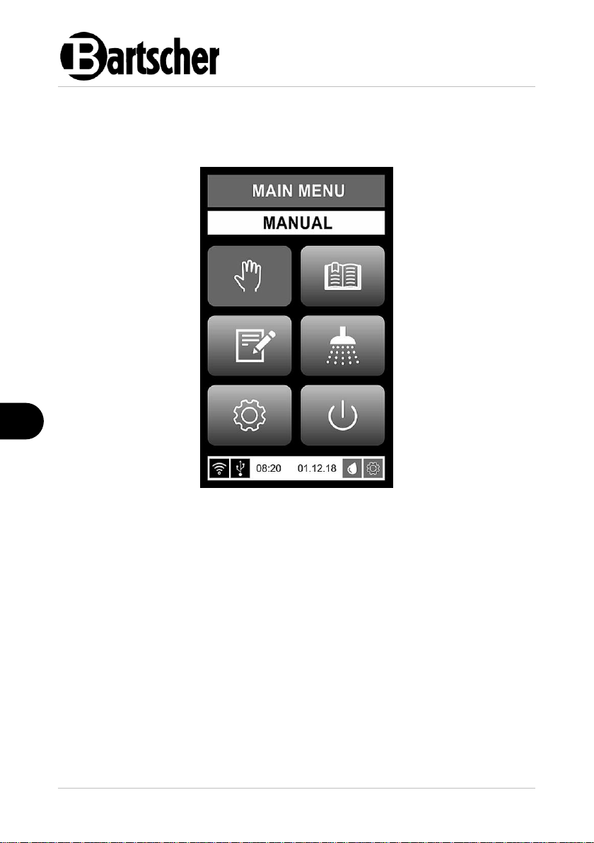
Main Menu Screen / Function Keys and Indicators
1. NAME OF CURRENT SCREEN
2. INFORMATION BAR
The name of the currently selected function is displayed in the information bar.
In the event of an error, the error message is also displayed in the information
bar.
3. MANUAL BAKING MODE
The manual baking mode is designed for fast baking in a single phase.
4. PROGRAMMED BAKING MODE
The programmed baking mode allows you to bake by selecting from a list one of
the pre-set baking programs.
5. BAKING PROGRAM EDIT MENU
This menu enables the user to activate or deactivate pre-set programs, create
new programs or edit the parameters of existing programs.
6. CLEANING MENU
In this menu, the user can choose from various cleaning programs.
36 / 86 117900
Page 39

Operating Instruction
EN
function available
function selected
function locked
Fig. 12
7. SETTINGS MENU
The settings menu gives access to several levels of parameters and information
8. OFF KEY
By pressing and holding this key for a few seconds, the user switches the oven
off.
9. STATUS BAR
The status bar shows the following information: time, internet connection, USB
status, date, periodical maintenance status and water filter status.
• Prior to first operation, clean the appliance and its equipment, observing instructi ons in section 6 'Cleaning'. Make sur e no water enters electric installation and connection box. Then thoroughly dr y the appliance and the entire equipmen t.
• Insert the bottom cover into the appliance. The cover acts as a spacer between t he heating element and left-over food tray.
• Carefully insert the connection box with th e heating element at the back edge of t he appliance. A pin in bottom part of th e connection box must enter a hole i n the main appliance. This way the con nection box is properly mounted.
Navigation and Colour Messages
Navigation and icon selection may be executed directly by touching icons on the
screen.
The orange colour is used as an indicator of a current position on the screen.
Function and mode icons have the following features:
Different colours of icons in the main menu screen inform the user of the status of a
function. An example of different statuses of one icon is shown in Fig. 12.
The grey colour of an icon indicates that a function can be activated.
The orange colour of an icon indicates that a function is currently selected.
The dark grey colour of an icon indicates that a function is blocked and therefore
cannot be selected and that it is not available for the product.
117900 37 / 86
Page 40

Operating Instruction
EN
Fig. 13
1. USB connection
2. Water filter
3. Internet connection
4. Periodical maintenance
5. Current time
6. Current date
Black USB indicator
Black colour of the icon
indicates no USB
communication.
Green USB indicator
Green colour of the icon
indicates that USB
communication is active and
working.
Red USB indicator
Red colour of the icon
indicates that USB
communication is active, but
due to an error is not working.
Status Bar
The status bar shows the following information:
USB Status Indicators
Information about the colour USB indicator icons:
38 / 86 117900
Page 41

Operating Instruction
EN
Black Internet indicator
Black colour of the icon
indicates no Internet
communication.
Green Internet indicator
Green colour of the icon
indicates that Internet
communication is active and
working.
Red Internet indicator
Red colour of the icon
indicates that Internet
communication is active, but
due to an error is not working.
Green water filter indicator
Green colour indicates that
the water filter does not
require
maintenance/replacement.
Orange water filter indicator
The orange colour of the filter
icon indicates that the filter
should be replaced soon and
that service should be
informed so that replacement
can be scheduled in the right
time.
Red water filter indicator
Red colour of the filter icon
means that the water filter has
not been replaced in due time
and that it needs to be
replaced immediately.
Internet Status Indicators
Information about the colour Internet indicator icons:
Water Filter Status Indicator
Information about the colour water filter indicator icons.
117900 39 / 86
Page 42

Operating Instruction
EN
NOTE!
As ovens can be installed in various
combinations, the water filter must be
checked manually by the user as it is used
to supply water to the entire appliance.
The filter icon is not an indicator of the
water filter status for the entire appliance.
Only the combination of information from
the filter icon and the manual inspection of
the water filter provides reliable
information on the status of the water filter.
Fig. 14: Water filter replacement required
Green service indicator
The green colour of the icon
indicates that no maintenance
is required.
Orange service indicator
The orange colour of the icon
indicates that an annual
service inspection will soon be
required and that the service
company should be notified to
schedule maintenance in due
course.
Red service indicator
The red colour of the icon
indicates that the annual
service has not yet been
performed and that it must be
performed immediately!
Status Indicators for Periodical Service Inspection/Maintenance
Information about the colour service indicators.
40 / 86 117900
Page 43

Operating Instruction
EN
NOTE!
As soon as the icons light up orange, an
extra precaution is automatically activated.
When the oven is switched on, the
'Periodical Maintenance' or 'Water Filter
Change Required' warning appears on the
main menu screen.
The warning is displayed and must be
acknowledged by pressing the
acknowledge key . The oven can then
be used. In some cases, for safety
reasons, the warning remains permanently
active until the inspection is completed. In
the meantime, the oven cannot be used.
Fig. 15: Periodical service inspection required
NOTE!
The service icon is only an indication for periodical maintenance. The
service icon is not an automatic error recognition system and does not
inform the user of errors that occur, as another system is responsible for
error recognition, error warning and error rectification.
117900 41 / 86
Page 44
Operating Instruction
EN
Fig. 16
• Przed pierwszym użyciem wyczyścić urzą dzenie i wypos ażenie zgodnie z e wskazówka mi zawartymi w punkcie 6 „Czyszczenie” . Uważać, a by do instalacji elektrycznej i s krzynki rozdzielcz ej nie dostała si ę woda. Nast ępnie dokładnie os uszyć urządz enie i element y wyposażenia.
• Setzen Sie die Boden-Abdeckung in das Becken ein. Osł ona pełni fu nkcję rozpór ki pomiędzy elemente m grzewcz ym a tacką na reszt ki jedzenia it d.
• Setzen Sie den Schaltkasten mit Heiz element vorsichtig auf den hinteren Rand des Gerätes. Sworzeń w dolnej części skrzynki rozdzi elczej musi wchodzić w otwór w urządzeniu g łównym. W taki sposób skrzyn ka rozdzielcza je st prawidło wo ustawiona.
Manual Baking Mode
The manual baking mode is activated by pressing the 'Manual' key (Fig. 16) in the
main menu screen.
After activation, the MANUAL screen (Fig. 17) shows the functions and baking
parameters. Manual operation is always set with the parameters which were used
during the last baking. They can be changed each time manual operation is
activated.
The MANUAL indicator consists of the following icons: INFORMATION and
OPERATION (Fig. 17)
42 / 86 117900
Page 45

Operating Instruction
EN
Fig. 17
1. Name of current screen
2. Information bar
3. Set baking temperature
Indicator of the set baking
temperature.
4. Pre-heating temperature
Pre-heating temperature indicator.
5. Baking chamber temperature
Indicator of the current baking
chamber temperature.
6. Baking time
Indicator of the set baking time
before activation of the manual
baking process.
7. Remaining baking time
Shows the time remaining in the
baking process.
8. Fan speed key
The fan speed can be set between
low (1) and the highest speed (10).
The fan speed can be set between
baking processes.
117900 43 / 86
Page 46

Operating Instruction
EN
9. Steam generators key
The steaming intensity is set in
intervals between 1 and 20. It can
only be set before baking.
It is not possible to use both
steaming systems at the same time,
therefore the icon for the steaming
system that is not selected is
blocked and dark grey.
10. Direct spray key
The steaming intensity is set in
intervals between 1 and 20. It can
only be set before baking.
It is not possible to use both
steaming systems at the same time,
therefore the icon for the steaming
system that is not selected is
blocked and dark grey.
11. Vapour extraction key
May be used to open or close the
fume flap.
12. Key for extending the baking time
The baking time can be added
between baking processes or at the
end of the baking process. Each
time it is activated, the baking time
is extended by 30 seconds.
13. Manual steaming function
Allows you to add steam manually.
14. START key
Pressing the START key starts the
baking process. Pressing and
holding the START key for 3
seconds activates the pre-heating
function.
15. STOP key
Can be used to stop the pre-heating
or baking process (direct activation
icon).
16. Undo key
With this key the user can return to
the previous indicator or to the main
menu.
44 / 86 117900
Page 47

Operating Instruction
EN
Setting the Manual Baking Process Parameters
To start the single-phase fast baking process, set the following parameters (Fig.
17):
– baking temperature
– time
– fan speed
– vapour flap
– direct spraying or steaming with the generator .
The parameters can be set one by one. They can be edited by pressing the icon on
the control panel and setting the value.
Baking Temperature
1. Press the displayed temperature icon.
The icon lights up in orange.
2. Select the desired temperature by pressing the pop-up menu that appears in the
display.
The highest temperature can be set up to 250°C.
3. Press the confirmation icon in the display to confirm the selected
temperature.
The set temperature is displayed on the right side of the temperature bar (Fig. 18).
The left temperature shows the current temperature in the oven.
The information bar shows that the oven is pre-heating.
When the set temperature is reached, an acoustic signal sounds and the inserted
product is displayed in the information bar.
Baking Time
1. Press on the current baking time icon.
The time icon lights up in orange.
2. Set the desired time by pressing the icon and using the keypad in the displayed
indicator to set the value.
3. Press the confirmation icon in the display to confirm the selected baking
time.
117900 45 / 86
Page 48

Operating Instruction
EN
Fig. 18
The total baking time is displayed on the right side of the time bar.
4. To extend the baking time, select the time add icon during or after the
baking process.
The end of the baking process is communicated by an acoustic signal and the
'Baking Finished' message is displayed in the information bar.
Fan Speed
1. Press the fan speed icon.
It changes colour to orange and the keypad is displayed.
2. Use the keypad to enter the desired value and confirm using the confirmation
icon in the display.
The fan speed can be set to low speed (value 1) or high speed (value 10).
3. Press the confirmation icon in the display to confirm the displayed fan
speed.
46 / 86 117900
Page 49

Operating Instruction
EN
Steaming
It is not possible to use both vapour systems at the same time, therefore the icon for
the vapour system that is not selected is blocked and dark grey.
Regardless of the colour of the steam icons, either icon can be selected.
1. To select one of the steam types, press the desired icon and hold it for 3
seconds, or press the multi-function key for 3 seconds.
The selected steam icon changes colour to orange and the value starts blinking.
The remaining steam icon becomes dark grey.
2. Select the desired number of steam intervals.
The steam intervals can be selected using the multi-function key, by pressing the
icon for 2 seconds and using the multi-function key or by briefly pressing the
selected icon and using the keypad in the display.
1. To confirm the number of intervals, press the multi-function key or press the
confirmation icon in the display.
2. To add further steaming intervals during the baking process, activate the 'Add
Steam' icon.
Information about the Steaming System
The creation of steam by spraying water on a fan is dubbed the direct steam
system. Steam is produced by water which evaporates on contact with the hot
surfaces in the baking chamber.
– The number of intervals can be set between 1 and 20.
– Information on the number of steam intervals is displayed in the steam
icon.
– The number of steaming intervals decreases during the baking process.
If necessary, the user can add more steaming intervals by pressing the 'Add
Steam' icon.
Information about the Steam Generator System
– The number of intervals can be set between 1 and 20.
– The information on the number of steaming intervals decreases
progressively during the baking process and shows the number of
remaining steaming intervals.
117900 47 / 86
Page 50

Operating Instruction
EN
– During the baking process, further steaming intervals can only be added
via manual steaming by pressing the 'Add Steam' icon.
The colour of the steam icon indicates the different states of the system (Fig. 19).
The dark grey colour of the icon indicates that the function is blocked. The grey
colour of the icon with a red steam cloud indicates that the steam generator is
heating up. The grey colour of the icon with a white steam cloud indicates that the
steam generator is ready for operation.
Adding Extra Steam During Baking Process
If an additional steaming interval is needed after the baking process has started and
the programmed steaming has finished, it can be added by activating the
icon.
By briefly pressing it once, the additional steaming interval is activated. Holding
down the icon activates the additional interval as long as the icon is held
down.
NOTE!
Steam cannot be added until the programmed steam intervals have
finished and the 30-second interval at the end of the set steam function
has elapsed.
48 / 86 117900
Page 51

Operating Instruction
EN
Add steam function
disabled
Add steam function
available
Add steam function
enabled
Fig. 19: Add steam function status
The colour of the 'Add Steam' icon shows the status of the function. The dark grey
colour of the icon indicates that the function is blocked. The grey colour of the icon
indicates that the 'Add Steam' function is available. The red colour of the icon
indicates that the 'Add Steam' function is enabled.
Vapour Extraction Flap
The vapour extraction flap icon is used to open and close the flap in the
vapour extractor in order to evacuate excess steam from the baking chamber if
necessary.
1. Press the icon to open the flap.
The colour of the icon shows whether the vapour extractor flap is open or not.
The grey colour of the icon with the horizontal flap drawing indicates that the
fume extraction flap is closed. The orange colour of the icon with the vertical
flap drawing indicates that the fume extraction flap is open.
Adding Baking Time to Baking Process
To extend the baking time, use the 'Extend Baking Time' icon. During the preheating phase, the icon is locked. Once the baking process has started, the baking
time can be extended any time. This can only be done by pressing the icon for
extending the baking time, and each touch extends the baking time by 30 seconds
(0.5 minute).
117900 49 / 86
Page 52

Operating Instruction
EN
Add time function
disabled
Add time function
available
Add time function enabled
Fig. 20: Add time function status
The colour of the 'Extend Baking Time' icon shows the status of the function. The
dark grey colour of the icon indicates that the icon is blocked (during the pre-heating
phase). The grey colour of the icon indicates that the icon is available for use. The
orange colour of the icon indicates that it has been selected and activated. The
numbers in the left corner of the icon show the additional time (each 0.5 unit
translates to 30 seconds).
If the 'Extend Baking Time' icon is pressed without setting one of the baking
parameters, the baking process will start for 30 seconds with the default
parameters. In this case, the time can be extended to 10 minutes by pressing the
icon repeatedly.
Starting the Pre-Heating Process
The baking process can be started when the door is closed, there are no errors and
the status bar displays the message 'READY'.
1. Press the START key to start the pre-heating phase. The 'BAKING' message is
displayed on the information bar.
2. Press the START key and keep it pressed for 3 seconds to start the pre-heating
phase. The 'PRE-HEAT' message appears in the information bar.
The end of the pre-heating phase is indicated by an acoustic signal and the status
of the information bar changes to 'INSERT PRODUCT'.
50 / 86 117900
Page 53

Operating Instruction
EN
Start of Baking Process
WARNING! Risk of burning!
When opening the appliance hot air and steam may escape.
Always open the appliance door with caution, using the door handle.
Always use oven mitts and protective gloves to operate the appliance.
Never put hands without oven mitts into the appliance!
Never slide baking sheets into the oven without oven mitts.
During operation, the housing and appliance door become very hot and
remain hot still for a while after switching the appliance off.
Never touch the inside or outside of the appliance door and housing without
oven mitts.
Baking sheets and grates get very hot during operation.
Never touch the grates nor baking sheets without oven mitts.
• Open the appliance door carefully. When opening the appliance door, move as
far away from the oven as possible, as hot air and steam may escape.
• Place the sheets with the products carefully on the baking surface and slide the
sheets backwards into the baking chamber. This is important so that the inner
glass pane is not damaged!
• Each product on a baking sheet must have sufficient space so that the hot air
and humidity can circulate unhindered around each product.
• The baking sheets should always be placed on grates.
• Always use baking trays that fit the oven and comply with the standards set by
the manufacturer.
• Always insert the baking trays into the oven only after pre-heating.
• Close the appliance door. Press the icon and the baking process starts.
The 'BAKING' message is displayed on the information bar.
Possible Actions and End of the Manual Baking Process
– The set temperature and baking time can be changed at any time.
– When the baking time is changed, the remaining baking time is adjusted
automatically.
– The appliance door can be opened at any time. The manufacturer
advises against opening the door during the baking process, as this
leads to a loss of energy, humidity and baking quality.
– Opening the appliance door interrupts the baking process and the baking
time continues to count down while the door is open.
117900 51 / 86
Page 54

Operating Instruction
EN
– The end of the baking process is communicated by an acoustic signal
and a message on the information bar: 'BAKING ENDED'.
– The acoustic signal can be interrupted by touching anywhere on the
screen.
– Quickly, but carefully empty the oven and close the door of the oven as
soon as possible so that the oven does not cool down too much before
the next baking process.
– To exit the manual baking process, press the icon and the main
menu screen will appear on the control panel. The icon is locked
during the baking process.
At the end of a working day, always perform the following steps:
– Switch the oven off using the main ON/OFF switch. Do not disconnect
the main power supply.
– Clean and dry the baking chamber and the appliance door, as they must
be completely dry after use.
– Clean the seal in the appliance door with a damp cloth only (do not use
any cleaning agent).
52 / 86 117900
Page 55

Operating Instruction
EN
Fig. 21: Program mode
1. Image
2. Selected program
3. Program number
4. Program name
5. Up
6. Down
7. Return to previous menu
• Przed pierwszym użyciem wyczyścić urzą dzenie i wyp osażenie zgodnie z e wskazówka mi zawartymi w punkcie 6 „Czyszczenie” . Uważać, a by do instalacji elektrycznej i s krzynki rozdzielcz ej nie dostała się woda. Następ nie dokładnie osusz yć urządz enie i eleme nty wyposażeni a.
• Setzen Sie die Boden-Abdeckung in das Becken ein. Osł ona pełni fu nkcję rozpór ki pomiędzy elemente m grzewcz ym a tacką na reszt ki jedzenia it d.
• Setzen Sie den Schaltkasten mit Heizele ment vorsichtig auf den hinteren edge of t he appliance. The pin in the connecti on box lower part must enter the hol e in the main appliance. This way the con nection box is properly mounted.
Programmed Baking Mode
The programmed baking mode is activated by clicking the 'Programmed Baking
Mode' icon in the 'Main Menu' screen (Fig. 17). This opens the list of activated
programs.
The screen shows 6 programs per page (Fig. 21). Use the Up and Down icons to
browse through the list of available programs.
117900 53 / 86
Page 56

Operating Instruction
EN
Fig. 22: Baking program
1. Program number
2. Program name
3. Information bar
4. Program time
5. Add steam
6. Percentage of oven load
7. Add baking time
8. Switching on
9. Stop key
10. Undo key
54 / 86 117900
Page 57

Operating Instruction
EN
Fig. 23
1. Image
2. Selected program
3. Program number
4. Program name
5. Up
6. Down
7. Undo key
Editing the Baking Program
You can access the 'Edit Program' list (Fig. 23) by pressing the 'Edit Program' icon
in the 'Main Menu' screen (Fig. 17). Convection ovens allow you to program and
activate up to 99 baking programs. Each program may consist of 6 phases of the
baking process. Each program has a number, a name, a pictogram and an
activation field.
The activation field shows whether or not a program is active and available in the
program mode list. If the program is not selected, it does not appear in the list of
programs active in program mode.
117900 55 / 86
Page 58

Operating Instruction
EN
Fig. 24
1. Program number
The information bar shows the
program number, name and image.
2. Program name
The name of the program is
displayed.
3. Program phases
Each program may have up to 6
phases. The icons are numbered
from 1 to 6 and show the number of
available phases. White colour
indicates an active phase, dim
colour indicates that no phase is
available for the selected program,
orange colour indicates that the
display currently shows the
parameters in this list.
4. Pictogram
To change the pictogram, press the
pictogram icon in the upper right
corner of the screen. A new screen
with a list of pictograms will be
displayed. Select the desired
pictogram. After selecting the
desired pictogram, the display
automatically returns to the 'Edit
Program' message of the selected
Changing Program Parameters
The parameters of the first phase differ slightly from those of the other phases. The
menu contains the pre-heating temperature in the first line under the numerical
symbols. In the other phases, the total baking time is displayed in the first line.
56 / 86 117900
Page 59

Operating Instruction
EN
program and displays the new
pictogram already.
5. Preparation function
In the first phase the pre-heating
time is displayed, while in the
other phases the total baking time
is displayed. When Preparation is
activated (ON), the oven prepares
itself to the set values of the
baking program.
6. Fan speed
The fan speed is displayed. Press
this parameter to change it. The
keypad will appear. Use the keypad
to enter the desired value and
confirm by pressing the confirmation
icon.
The fan speed can be set in the
range of 0–2.
7. Baking time
Shows the time of the selected
baking phase.
8. Baking temperature
Shows the set temperature. To
change the parameter, select the
parameter by pressing it. The
keypad will appear. Use the keypad
to enter the desired value and
confirm by pressing the confirmation
icon.
The baking temperature may be set
to max. 250°C.
117900 57 / 86
Page 60

Operating Instruction
EN
9. Steaming type
Shows the type of the set steaming.
By pressing the icon you may
change the selected steaming type.
10. Steam intensity
Shows the set steam intensity. To
change the parameter, select the
parameter by pressing it. The
keypad will appear. Use the keypad
to enter the desired value and
confirm by pressing the confirmation
icon.
The steam intensity may be set from
1 to max. 20 steam intervals.
11. Pause after steaming
Shows the set interval of the
appliance. To change the
parameter, select the parameter by
pressing it. The keypad appears;
use it to enter the desired value.
Confirm by pressing the
confirmation icon.
12. Setting the vapour extraction flap
Only one of the two different flap
positions may be programmed
(ON/OPEN or OFF/CLOSE).
13. AirFresh function icon
Air refreshment in the thermal
processing chamber may be
activated. It can be set to ON or
OFF.
14. Undo key
Icon used to return to the 'Edit
Program' menu.
15. Deletion of the recently edited
phases
The last active phase in the program
can be deleted by selecting the
'Delete Last Edited Phase' icon. The
action must be confirmed by
pressing the confirmation icon in the
pop-up menu that appears in the
display.
16. Adding a new baking phase
Adding a new phase to the program
is done by pressing the 'Add New
Phase' icon. Confirm the action by
pressing the confirmation icon in the
pop-up menu that appears in the
display.
58 / 86 117900
Page 61

Operating Instruction
EN
Fig. 25
1. Total time
Shows the total baking time of the
baking cycle.
2. Timer alarm
To set the timer alarm, select the
timer icon. A new screen appears
where you can use the keypad to
enter and confirm the desired value.
Adding timer alarms
Five different additional timer alarms may be set for various warnings during the
baking process. The timer alarms can be set independently of the main alarm,
which communicates the end of the baking process. Select any phase icon except
the first phase icon, as the first phase always shows the pre-heating temperature
and not the total time.
When the phase icon is selected, the screen with the total time information appears.
117900 59 / 86
Page 62
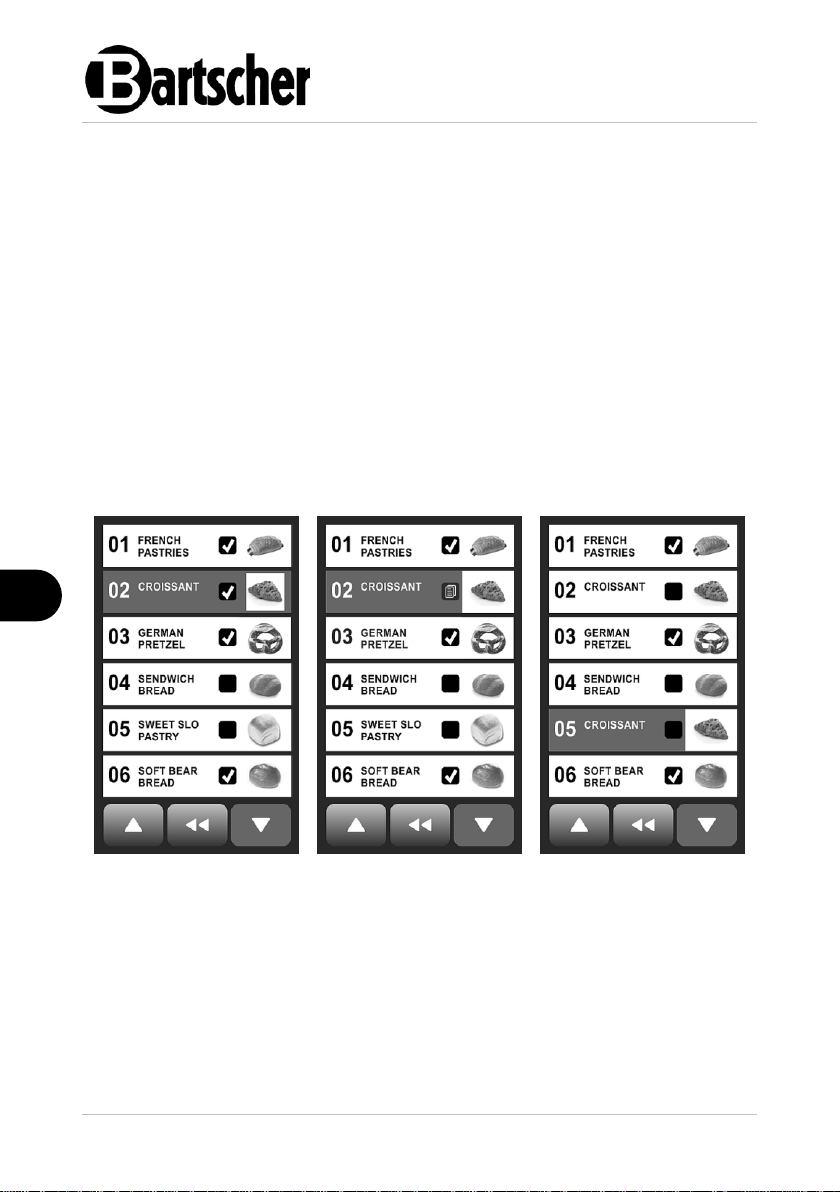
Operating Instruction
EN
3. Adding a timer alarm
Adding a new timer alarm to the
program is done by selecting the
'Add New Timer Alarm' icon. The
action must be confirmed by
pressing the confirmation icon on
the pop-up menu that appears in the
display.
4. Deleting timer alarms
Delete the last alarm that was
added to the program by pressing
the 'Delete Last Timer Alarm' icon.
Confirm the action by pressing the
confirmation icon in the pop-up
menu that appears in the display.
Fig. 26
Fig. 27
Fig. 28
Program Copying
Programs may be copied. A program may be copied from one location to another.
1. Hold down the image of a program to be copied.
2. Then select the desired program number and press it.
The program is copied to the selected number.
60 / 86 117900
Page 63

Operating Instruction
EN
Fig. 29
1. Cleaning-I
This is designed for daily cleaning. It
lasts for approx. 1 hour and 20
minutes.
2. Cleaning-II
For intensive cleaning. Lasts
approx. 1 hour and 20 minutes.
3. Cleaning mode with water only
Cleaning without cleaning agents
4. Manual cleaning mode
Used for manual cleaning
Cleaning Programs
The convection ovens have four different cleaning programs.
The cleaning programs can be selected by touching the screen or by rotating and
pressing the multi-function key in the cleaning menu.
117900 61 / 86
Page 64

Operating Instruction
EN
Fig. 30
Fig. 31
Cleaning with Cleaning Agent
To start the cleaning program, the appliance door must be closed. If the appliance
door is not closed, a warning sign appears in the display and the information bar
shows 'Door Open'.
When the appliance door is closed and no other alarms are detected, the status of
the information bar changes to 'Press Start'. The 'Start' icon is displayed in green.
Pressing the 'Start' icon starts the pre-cleaning phase. In the information bar, the
status changes to 'Preparation' and the time bar shows the time remaining in the
cleaning phase. The pre-cleaning phase lasts approx. 20 minutes.
The end of the pre-cleaning is communicated by a blinking green light and an
acoustic signal. A message appears indicating the need to add a cleaning agent
and put on protective gloves. Once the detergent has been added and the door
closed, cleaning continues in a second phase.
62 / 86 117900
Page 65

Operating Instruction
EN
Fig. 32
Fig. 33
Fig. 34
WARNING! Risk of scalding!
During the cleaning process, the oven is filled with hot water. The
appliance door must remain closed until the cleaning process is complete.
The end of the cleaning process is indicated by an acoustic signal and the
'Ready' status displayed in the information bar.
WARNING!
Always use protective gloves when using cleaning agents!
Carefully read the instructions on the cleaning agent packaging!
Store the cleaning agent in a dry, dark and locked place, out of the reach
of children.
Do not store cleaning products in the vicinity of beverages and food
products and ensure that they do not come into contact with food
products and beverages!
Solely use cleaning agents authorised by the manufacturer!
117900 63 / 86
Page 66

Operating Instruction
EN
Filling with Cleaning Agent
NOTE!
For cleaning the appliances, we recommend Bartscher LG 50 convection
oven cleaning agent, Art. No. 173286.
1. Open the appliance door carefully.
2. Pour 100 ml of the cleaning agent on the bottom of the baking chamber.
3. Close the appliance door.
If the appliance door is not closed, a message appears indicating that the door must
be closed.
After the cleaning agent has been poured in, a new message appears indicating the
cleaning process in progress and the remaining cleaning time (Fig. 32).
Once the cleaning agent has been poured in, it is no longer possible to stop the
cleaning process, so the Stop and Undo icons are locked. The display also shows a
warning to keep the door closed (Fig. 33).
When the cleaning process is complete, a new screen appears with an information
bar displaying the 'Done' message (Fig. 34). The end of the cleaning process is
communicated by a blinking green light and an acoustic signal.
When cleaning is complete, the oven switches off.
The cleaning program may be switched off by opening the door, selecting the Stop
icon; otherwise, it happens automatically 10 seconds after the acoustic signal is
generated.
64 / 86 117900
Page 67

Operating Instruction
EN
Wash Program
The wash program is a program for basic cleaning of the oven without cleaning
agents. It lasts approx. 30 minutes. The duration may vary depending on the initial
temperature in the baking chamber. The use of a cleaning agent is not required.
Washing with water is used to clean off dust and crumbs from the previous baking
process.
When the appliance door is closed and no other alarms are detected, the status of
the information bar changes to 'Press Start'. The 'Start' icon changes to green
colour. Pressing the 'Start' icon starts the water wash program.
The appliance door must remain closed during the water wash process.
When the wash process is complete, a new screen appears with an information bar
displaying the 'Done' message. The end of the washing process is communicated
by a blinking green light and an acoustic signal.
When water wash is complete, the oven switches off.
The wash program may be switched off by opening the door, selecting the Stop
icon; otherwise, it happens automatically 10 seconds after the acoustic signal is
generated.
Manual Cleaning
The manual cleaning program is designed for semi-automatic cleaning of soiling in
the oven that cannot be removed by the automatic cleaning programs alone.
Manual cleaning is the most powerful of all cleaning programs and combines the
automatic and manual phases. It lasts approx. 2 hours.
1. To start this program, the appliance door must be closed.
If the appliance door is not closed, the screen displays the 'Close Door' warning.
The screen displays 'Press Start', the time of the pre-wash phase, the 'Undo' icon
and the 'Start' icon.
2. Select the 'Start' icon to start preparing the oven for the cleaning process (precleaning).
At the end of the preparatory process, a new screen appears with the 'Pour the
Cleaning Agent' message, and 'Warning, Wear Protective Gloves'.
The end of the preparatory process is also communicated by an acoustic signal.
3. Now open the appliance door slowly and carefully.
4. Spray the cleaning agent (read the cleaning agent instructions carefully) on the
inner surfaces of the baking chamber.
5. Clean the baking chamber manually, using protective gloves.
6. Close the appliance door when you have finished manual cleaning.
Cleaning (phase I) begins.
117900 65 / 86
Page 68

Operating Instruction
EN
After approx. 20 minutes, phase I cleaning is complete. A new screen appears with
the 'Fill with Cleaning Agent' message and the requirement to wear protective
gloves.
The end of the cleaning process is also communicated by an acoustic signal.
7. Again, open the appliance door slowly and carefully.
8. Spray the cleaning agent (read the cleaning agent instructions carefully) on the
inner surfaces of the baking chamber.
9. Clean the baking chamber manually, using protective gloves.
10. Close the appliance door when you have finished the second manual cleaning.
Cleaning (phase II) continues.
When cleaning (phase II) is complete, the oven switches off.
66 / 86 117900
Page 69

Operating Instruction
EN
Fig. 35
Fig. 36
1. LOG IN/OUT
This option is intended for
specialised personnel who have
access rights to locked options.
2. SCREEN BRIGHTNESS
Press the screen brightness icon to
set the screen brightness.
3. SOUND
Press the sound icon to set the
desired sound using the icons.
4. TIME
Here you can set the date (day,
month and year), time (hours,
minutes and seconds) and day of
the week (DOW).
6.2 Settings
Settings Menu
The Settings menu can be activated by pressing the 'Settings' icon in the main
menu screen (Fig. 35). The settings mode includes 10 options (Fig. 36).
117900 67 / 86
Page 70

Operating Instruction
EN
5. GENERAL INFORMATION
Displays basic information about the
oven, such as oven type, serial
number, factory number,
manufacturer, year of manufacture,
installation date, etc.
6. LANGUAGE
Various languages may be selected.
Simply select the desired language
and return to the menu using the
Undo icon. The menu will be
displayed in the newly set language.
7. AUTO. PREHEATING
This option allows you to set an
automatic preparation process at a
specific time (e.g., in the morning
before the start of the working day).
Please read the following section
only about the preparation option.
8. PARAMETERS
Only qualified personnel may
access the parameters and set them
from scratch. Access is possible via
the Log In/Log Out option.
9. LICENCE PROLONGATION
Is an option only available to
maintenance and service personnel.
10. TRANSFER
Access is possible via the Log
In/Log Out option. Allows data to be
transferred to or from a USB drive.
68 / 86 117900
Page 71

Operating Instruction
EN
Fig. 37
1. BASIC SETTINGS
Settings for temperature units,
display mode, locked and manual
programs, etc.
2. PASSWORD
Passwords for service use.
3. SOUND
Buzzer settings (on/off)
4. GENERAL SETTINGS
Condensation hood settings, door
lock, vapour hood flap, steam
settings.
5. TEMPERATURE
Setting of maximum and minimum
temperatures for steam generator
and baking chamber, etc.
6. STEAMING SETTINGS
Setting of steam interval time,
interval between steam intervals,
etc.
Parameter Settings
117900 69 / 86
Page 72

Operating Instruction
EN
7. FAN MOTOR
Setting of fan direction, fan speed
(min./max.).
8. POLARITIES
Setting of the standard vapour
extraction position.
9. VAPOUR EXTRACTION FLAP
Setting the time to open and close
the fume extraction flap.
10. CLEANING
Settings for cleaning parameters.
11. LIST OF ERRORS
Summary of all errors and their
significance.
12. INTERNET
Internet settings of server
addresses, DHCP, Ethernet
communication, etc.
13. STATISTICS
All data for man-hours, days to
service.
14. CONTROL SETUP
Contains the I/O menu for service.
Activating Timer for Automatic Pre-Heating
Pre-heating the oven is a function by which the appliance is pre-heated before
baking. This function reduces the total operating time. Namely, the steam generator
needs approximately 30 minutes (counting from a cold state) until it is ready for
operation. The settings for automatic pre-heating can be found in Fig. 38.
NOTE!
The oven pre-heating function can only be set one day in advance. The
settings must be repeated in advance for each subsequent day.
70 / 86 117900
Page 73

Operating Instruction
EN
Fig. 38
1. ACTIVATION
Parameter 16.07 can be used to
enable or disable pre-heating. If the
oven has already been pre-heated,
the parameter automatically
switches to OFF.
2. START TIME
Parameter 16.08 can be used to set
the time by which the appliance
should be ready for operation.
3. START DAY
Parameter 16.09 shows the day on
which the pre-heating is activated.
4. PROGRAM NUMBER
Parameter 16.10 can be used to
select the number of baking
programs. (Only active programs
can be selected).
117900 71 / 86
Page 74
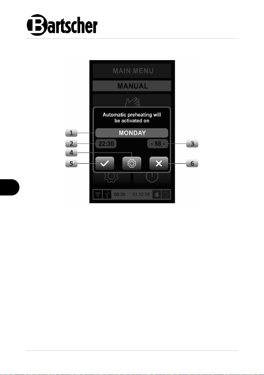
Operating Instruction
EN
Fig. 39
1. DAY SELECTION
Indicator of the day for which
automatic pre-heating is activated.
2. TIME
Shows the time for which the
appliance is ready for operation.
3. PROGRAM NUMBER
Shows the number of the selected
program.
4. SETTINGS
Shortcut to the parameter settings
for automatic pre-heating.
5. CONFIRMATION
6. CANCEL
Pop-up menu before the oven is switched off:
72 / 86 117900
Page 75

Operating Instruction
EN
Data Transfer
File transfer is carried out via the USB port.
A USB flash drive is required for file transfer. The volume can be up to 32 GB.
NOTE!
Ensure that the USB flash drive is empty before copying programs to it.
The transfer of programs may only be carried out by authorised personnel with an
admin password. Please contact your local dealer to obtain the password.
USB Transfer
1. To transfer a program, go to the main menu.
2. Insert the USB drive into the USB port on the left side of the appliance.
In the main menu, the USB icon in the status bar must be green .
3. When the icon is green, go to Settings, select 'Log In' and use the cook's
password.
This will enable option 9 (Transfer) in Settings.
4. Select the 'Transfer' option.
A new window opens (Fig. 40).
5. To transfer programs to the USB drive, first select the 'Programs'
option (Fig. 41) and press to download to the USB. When the process is
complete, a pop-up menu 'Transfer Completed' is displayed.
117900 73 / 86
Page 76
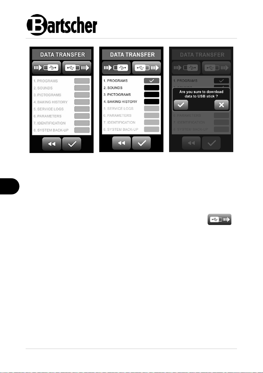
Operating Instruction
EN
Fig. 40: Data transfer
Fig. 41: Program
selection
Fig. 42: Transfer
completed
The program is now transferred to the USB drive.
6. If pictograms and sounds are also to be transferred to another oven, 'SOUND'
and 'IMAGES' must be selected before transferring. The options 'LOGS' or
'PARAMETERS' cannot be selected with the admin password, as these options
are for service only!
7. To import programs from a USB drive, repeat the process, but select
and continue with the USB transfer instead.
74 / 86 117900
Page 77

Operating Instruction
EN
Fig. 43: Manual mode with error display
Fig. 44: Main menu with error display
Error Detection
If an error occurs during the manual baking process, the error message is displayed
in the information bar. The information bar shows the name and number of the error
that occurred (Fig. 43).
The first phase should be to reset the program.
1. Press the Stop icon to end the baking program.
2. Return to the main menu by activating the icon.
3. In the main menu, press the icon (Fig. 44) in the right corner of the
information bar, next to the error message.
4. If resetting does not clear the error, contact the service company.
117900 75 / 86
Page 78

Operating Instruction
EN
Error number
Error description
Basic setting
ERR01
TF1 Chamber thermal fuse
AN
ERR02
TF2 Steam generator thermal fuse
AN
ERR05
BIM1 Fan motor 1 pre-heating
AN
ERR06
BIM2 Fan motor 2 pre-heating
AN
ERR07
TP1 OVR Chamber temperature too high
AN
ERR08
TP1 UNDR Chamber temperature too low
AN
ERR11
TP3 OVR Sensor temperature too high
AN
ERR12
TP3 UNDR Sensor temperature too low
AN
ERR27
PHLOSS L1 L1 voltage too low
AN
ERR28
PHLOSS L2 L2 voltage too low
AN
ERR29
PHLOSS L2 L3 voltage too low
AN
ERR30
Water level 1
AN
ERR31
Water level 2
AN
ERR32
FQ1 Communication loss
AN
ERR33
FQ1 Voltage too low
AN
ERR34
FQ1 Fan
AN
ERR35
FQ1 - HW Hardware
AN
ERR36
FQ1 - IOL Overload Reversing
AN
ERR37
FQ1 - EEP Save parameters
AN
ERR38
FQ1 - OLT Overload
AN
ERR39
FQ1 - POT Phase failure
AN
ERR40
FQ1 - ETH Temperature too high –
controller
AN
ERR41
FQ1 - OHT Temperature too high
AN
ERR42
FQ1 - OVT Current value too high
AN
ERR43
FQ1 - GFT Ground
AN
The following table describes the possible error messages:
76 / 86 117900
Page 79

Operating Instruction
EN
ERR44
FQ1 - Out of phase
AN
ERR45
FQ1 - OVT High voltage
AN
ERR46
TP1 OVERHEAT Chamber temperature too
high
AN
ERR48
TP3 OVERHEAT Steam generator
temperature too high
AN
ERR49
TP4 OVRH
AN
ERR50
TP5 OVRH
AN
ERR51
TP6 OVRH
AN
ERR52
TP7 OVRH
AN
ERR53
TP8 OVRH
AN
ERR54
TP9 OVRH
AN
ERR55
TP10 OVRH
AN
ERR56
TRIAC1 28
AN
ERR57
TRIAC1 35
AN
ERR58
TRIAC1 36
AN
ERR59
TRIAC1 37
AN
ERR60
TRIAC1 T
AN
ERR61
IO OVRTMP
AN
ERR62
FQC2 C-LOSS
AN
ERR63
FQ-LVT
AN
ERR64
FQ2-FAN
AN
ERR65
FQ2-HW
AN
ERR66
FQ2-IOL
AN
ERR67
FQ2-EEP
AN
ERR68
FQ2-OLT
AN
ERR69
FQ2-POT
AN
ERR70
FQ2-ETH
AN
ERR71
FQ2-OHT
AN
117900 77 / 86
Page 80

Cleaning and Maintenance
EN
ERR72
FQ2-OVT
AN
ERR73
FQ2-GFT
AN
ERR74
FQ2-COL
AN
ERR75
FQ2-OVT
AN
ERR76
TRIAC2 28
AN
ERR77
TRIAC2 35
AN
ERR78
TRIAC2 36
AN
ERR79
TRIAC2 37
AN
ERR80
TRIAC2 T
AN
ERR90
TOUCH
AN
ERR91
ENCODER
AN
Tab. 1
7 Cleaning and Maintenance
7.1 Safety Instructions for Cleaning
• Before cleaning, disconnect the appliance from the power supply.
• Leave the appliance to cool down completely.
• Make sure water does not enter the appliance. Do not immerse the appliance in
water or other liquids during cleaning. Do not clean the appliance with a
pressurized water jet.
• Do not use any sharp or pointed, nor metal implements (knife, fork, etc.). Sharp
or pointed implements may damage the appliance, and when in contact with live
parts, they may cause electric shock.
• For cleaning, do not use any scouring agents that contain solvents nor corrosive
cleaning agents. They may damage the surface.
• Do not use aggressive cleaning agents for cleaning; solely use agents approved
by the manufacturer.
• Only cleaners that are certified and approved for use in the food sector may be
used to clean the inside of the oven. Read the instructions on the cleaning
agents carefully to ensure that they can be used inside the oven.
• Read the instructions on the cleaning products carefully and observe the
instructions to ensure safe use of the cleaning products.
• Always wear protective gloves when working with cleaning products.
• Do not use any tools or cleaning equipment to clean the appliance.
78 / 86 117900
Page 81

Cleaning and Maintenance
EN
Appliance Door Seal
1. At the end of each working day, the
appliance door seal should be cleaned
with a soft, damp cloth.
ATTENTION!
Do not use any cleaning agents to
clean the seal, as these may dissolve
the seal material.
Fig. 45
WARNING!
The appliance must always be cooled down internally and externally to
room temperature (approx. 25°C) before cleaning!
7.2 Cleaning
Daily Cleaning
WARNING!
After daily use, the oven must be cooled to room temperature (approx.
25°C) before cleaning.
The following appliance components must be cleaned daily:
– door seals
– inner glass pane of the appliance door, inner side of the appliance door
– baking chamber
– control panel
– LED interior lighting
– condensate collecting tank
– used baking trays
117900 79 / 86
Page 82

Cleaning and Maintenance
EN
1. Open the appliance door wide.
2. Pull out (without removing) the two
Teflon-coated locking tabs located on
the inner glass pane of the appliance
door and rotate them 180°.
3. Open the inner glass pane carefully.
When cleaning, take care not to
damage the LED light bars.
Fig. 46
Inner Glass Pane of the Appliance Door
We recommend that you clean the inner glass pane of the appliance door at least
once a month; proceed as follows:
4. Clean the inner glass pane on both sides, as well as the inner side of the
appliance door with a soft, damp cloth. Use a mild cleaning agent when
required. Wipe with a clean cloth and dry the cleaned surfaces.
5. After cleaning, close the inner glass pane and fasten both locking latches.
6. Check again that the inner glass pane is secure and fastened securely and only
then do close the appliance door.
Baking Chamber
1. The baking chamber of the appliance should be cleaned regularly at the end of
the working day and more often if necessary. With regular cleaning you may
avoid burning leftovers of baked goods and roasts.
NOTE!
Clean the appliance manually or use one of the cleaning programs. Follow
the instructions in section 'Cleaning Programs'.
2. Clean the baking chamber with a soft, damp cloth and a suitable cleaning agent.
Observe instructions of such a cleaning agent's manufacturer.
80 / 86 117900
Page 83

Cleaning and Maintenance
EN
Fig. 47
Control Panel
Regular cleaning of the control panel is necessary for good performance and good
visibility on the screen.
1. Clean the control panel only with a soft, slightly damp cloth.
ATTENTION!
Do not use any cleaning agents to clean the control panel.
Condensate Collecting Tank
The condensate collecting tank is located under the appliance door. It collects water
and soiling falling from the chamber and the door. We recommend that the tank is
cleaned daily after the cleaning process or before the start of the working day.
Use a damp cloth to clean the condensate collecting tank to remove soiling, dust
and accumulated water. Ensure that the water drainage hole in the condensate
collecting tank is clean.
LED interior lighting lamps
ATTENTION!
The LED lamps of the interior lighting must be cleaned regularly.
Do not look directly into the switched-on LED lamps.
Cleaning of the LED lamps is only permitted when the oven is switched off
and the interior lighting is not in operation.
Cleaning is only permitted when the LED lamps are completely cooled
down.
1. LED lamps should only be cleaned with a soft, damp cloth without a cleaning
agent.
117900 81 / 86
Page 84

Cleaning and Maintenance
EN
For easy cleaning of the baking chamber, the
guide rails can be removed from the appliance
manually, without using any tools.
1. To remove the side panels with guide rails,
unlock the two pins.
2. Lift guide rails and pull them out of the
baking chamber (Fig. 48).
Fig. 48
Baking Sheets
1. Remove the used oven sheets, grill grates and food containers from the
appliance.
2. Clean them according to the instructions of manufacturers of respective
appliances.
Monthly Cleaning
Housing
1. Clean the outside of the oven with a damp, soft cloth or with a mild cleaning
agent for degreasing metal surfaces.
2. Clean the outside of the door glass with a damp, soft cloth or with a mild glass
cleaning agent.
Baking Chamber
82 / 86 117900
Page 85

Cleaning and Maintenance
EN
The rear wall (fan cover) of the baking
chamber can also be removed for cleaning.
3. Loosen manually the four large fixing
screws at the rear wall (fan cover) (Fig.
49).
4. Carefully remove the rear wall (fan
cover|) from the appliance and clean it.
5. Clean the rear area behind the rear wall
(fan cover) carefully, using thick
protective gloves, in order not to cut
yourself with sharp parts of the fan and
the oven.
ATTENTION!
When cleaning the area behind the rear
wall (fan cover), be careful not to damage
the temperature sensors located at the
top left side, as well as heating elements.
Heating elements and temperature
sensors must not be cleaned.
Fig. 49
6. After cleaning, re-install the rear wall (fan cover) back in place and fix it four
fixing screws manually, without using tools.
7. Finally, check that all components are firmly in place.
Water spray nozzle
It is necessary to clean the water spray nozzle regularly, because during the baking
process particles of different types and sizes are blown off the products and can
clog the water spray nozzle.
The water spray nozzle is located at the upper wall of the chamber.
1. For cleaning, unscrew the water spray nozzle (Fig. 50).
2. After removal, wash the water spray nozzle using water with a mild detergent.
3. After cleaning, rinse the individual components of the water spray nozzle in
fresh water (Fig. 51).
4. Re-install the water spray nozzle in the appliance.
117900 83 / 86
Page 86

Cleaning and Maintenance
EN
Fig. 50
Fig. 51
7.3 Maintenance
ATTENTION!
The following maintenance and cleaning work must only be carried out by
qualified and specialised personnel and never by the user of the
appliance!
Cleaning the Condensate Collecting Tank with Trap at the Oven Rear Wall
Every 3–6 months, a preventive service inspection and cleaning of the outlet
channel and the condensate collecting tank with trap, located at the rear of the
oven, should be carried out.
The service technician should carry out the following steps:
– cool the oven down to room temperature before maintenance work;
– disconnect the oven from the main electricity supply;
– find the condensate collecting tank with the trap at the rear wall of the
oven for cleaning;
– unscrew the trap lid;
– clean the condensate collecting tank;
– clean the ends of all the supply lines to the trap lid;
– screw the cover back on;
– finally, check that all wires have been returned to their original positions
and that all connections have been tightened securely.
84 / 86 117900
Page 87

Cleaning and Maintenance
EN
Cleaning the Oven Electrical Components Off of Flour and Other Soilings
Every 3–6 months, carry out a preventive service inspection of the oven and
cleaning inside the electrical parts of the oven (control cabinet). These service
inspections and cleaning works should be carried out especially if the regulations
for the correct and safe setting up of the oven and safety measures for a safe
working environment are not met and observed.
The interior of the electrical part of the oven may contain small amounts of dry flour
and other impurities or, in extreme cases, grease, which can seriously and
permanently damage the electrical components.
Inspection, disassembly and cleaning of the electrical part of the oven must only be
carried out by a qualified electrician, taking into account the following phases:
– cool the oven down to room temperature;
– disconnect the oven from the main electricity supply;
– unscrew the two screws on the left side cover of the oven;
– carefully remove the metal side panels of the oven and, under no
circumstances, touch the electrical components;
– visually inspect the interior of the electrical parts, looking for flour, other
soilings, grease or moisture;
– use a vacuum cleaner to clean flour and other soilings; vacuum the entire
area thoroughly. It is necessary to use a vacuum cleaner with a
plastic adapter at the ends of the hose. Do not touch the electrical
parts (neither with your hands nor with the vacuum cleaner
components);
– after inspection and cleaning, immediately and carefully reposition the
side cover in its original position and fix it with screws.
117900 85 / 86
Page 88

Disposal
EN
Electric appliances are marked with this symbol. Electrical
appliances must be disposed of and recycled in a correct
and environmentally friendly manner. You must not dispose
of electric appliances with household waste. Disconnect the
appliance from the power supply and remove power cord
from the appliance.
8 Disposal
Electrical Appliance
Electrical appliances should be returned to designated collection points.
86 / 86 117900
 Loading...