


ELEKT R I S C H E F R I T T E U SE
ELECTRIC FRYER
FRITEUSE ÉLECTRIQUE
FRIGGITRICE ELETTRICA
FREIDORA ELÉCTRICA
FRITADEIRA ELÉTRICA
ELEKTRISCHE FRITEUSE
DE
296630 / FRE91M00
296970 / FRE92M00
Rev.-Nr.: 01-2017
FRYTOWNICA ELEKTRYCZNA
INSTALLATIONS-, BEDIENUNGSUND WARTUNGSANWEISUNGEN
INSTALLATION, OPERATING
AND MAINTENANCE NSTRUCTIONS
MANUEL D'INSTALLATION,
D'UTILISATION ET D'ENTRETIEN
MANUALE DI INSTALLAZIONE,
USO E MANUTENZIONE
MANUAL DE INSTALACIÓN,
USO Y MANTENIMIENTO
MANUAL DE INSTALAÇÃO,
UTILIZAÇÃO E MANUTENÇÃO
HANDLEIDING VOOR INSTALLATIE,
GEBRUIK EN ONDERHOUD
WSKAZÓWKI DOTYCZĄCE INSTALACJI,
UŻYTKOWANIA I KONSERWACJI
GB
FR
IT
ES
PT
NL
PL

DE
Technische Änderungen vorbehalten!
GB
FR
IT
ES
PT
NL
Technical changes reserved!
Sous réserve de modifications techniques !
Ci riserviamo la possibilità di introdurre modifiche tecniche!
¡Se reserva el derecho a introducir modificaciones técnicas!
Sujeito a alterações técnicas!
Technische wijzigingen voorbehouden!
PL
Wprowadzanie zmian technicznych zastrzeżone!

1. TABLE OF CONTENTS
ENGLISH
1. TABLE OF CONTENTS ..................................................................................................................... 1
2. INDEX ................................................................................................................................................. 2
3. SAFETY .............................................................................................................................................. 3
4. GENERAL INFORMATION AND WARNINGS ................................................................................... 4
4.1. General guidelines ................................................................................................................... 4
4.2. Description of the appliance ..................................................................................................... 4
4.3. Index plate ................................................................................................................................ 5
4.4. Exchange of components (service technician) ........................................................................ 5
4.5. Elements and accessories ....................................................................................................... 5
4.6. Protection devices .................................................................................................................... 6
5. USE AND OPERATION ..................................................................................................................... 6
5.1. Description of the controls . ...................................................................................................... 6
5.2. Switch the appliance on and off ............................................................................................... 7
5.3. Filling up the container ............................................................................................................. 7
5.4. Draining the container .............................................................................................................. 8
5.5. Guidelines on how to use the appliance .................................................................................. 8
6. CLEANING AND MAINTENANCE ..................................................................................................... 9
6.1. Guidelines on cleaning and maintenance ................................................................................ 9
6.2. Correct maintenance (service technician) ................................................................................ 9
6.3. Cleaning the container ............................................................................................................. 9
7. TROUBLESHOOTING ..................................................................................................................... 10
8. INSTALLATION ................................................................................................................................ 11
8.1. Packaging and unpacking ...................................................................................................... 11
8.2. Installation (service technician) .............................................................................................. 11
8.3. Connection to the mains (service technician) ........................................................................ 12
8.4. Installation of the appliance in a line ...................................................................................... 12
8.5. Check-up ................................................................................................................................ 13
9. SETTINGS ........................................................................................................................................ 13
10. APPLIANCE DISPOSAL .................................................................................................................. 13
ATTACHMENTS ....................................................................................................................................... I
GB
1

ENGLISH
2. INDEX
GB
A
APPLIANCE DISPOSAL 13
C
Check-up 13
Cleaning the container 9
Connection to the mains 12
Correct maintenance 9
D
Description of the appliance 4
Description of the controls 6
E
Elements and accessories 5
Exchange of components 5
G
General guidelines 4
Guidelines on cleaning 9
Guidelines on how to use the appliance 8
Guidelines on regular use of the appliance 8
I
Index plate 5
Installation 11
Installation of the appliance in a line 12
L
Longer interval in the use of the appliance 8
M
Maintenance 9
P
Packaging 11
Protection devices 6
S
SAFETY 3
Switch the appliance on and off 7
T
TROUBLESHOOTING 10
U
Unpacking 11
2

3. SAFETY
instructions in the instruction manual
before you use the appliance.
The instruction manual contains general
information on how to safely use and maintain the
appliance. Retain the manual for future reference.
60335-1 and 60335-2-37 regulation.
mains power cable may be replaced by the
manufacturer or service personnel only.
The manufacturer took extra care when designing
and manufacturing to prevent any safety or health
hazard to the personnel operating the appliance.
Please read carefully the guidelines in the
instruction manual and instructions placed directly
onto the appliance. Above all, observe all the
safety instructions.
Do not intervene in or remove the protective
devices installed in the appliance. Noncompliance may lead to severe safety and health
hazard against people. We recommend to perform
a few tests to know the layout and main functions
of the control panel, particularly those to switch
the appliance on and off.
The appliance is intended only for the use it has
been designed for and any other use is
considered as the use not in compliance with the
intended use.
The manufacturer is not liable for material
damage or damage to person caused by
misapplication or incorrect application of the
appliance.
Any maintenance work that requires special
technical licence or special skills may be
performed by qualified personnel only.
To provide hygiene and protect foods from dirt, all
the elements that have direct or indirect contact
with the foods and all border areas must be
thoroughly cleaned. Use only the cleaning agents
intended for use in contact with food and avoid
using flammable agents or harmful to health.
Read carefully the guidelines and
Electric installation conforms to CEI EN
To prevent any hazard, the damaged
ENGLISH
After each use of the appliance make sure that all
the heating elements and control elements have
been switched off and the cable unplugged.
In case of prolonged interval in using the
appliance disconnect all power supply cables and
thoroughly clean the inside and outside elements
of the appliance.
In direct connection to the mains the
safety switch should be supplied where wire
joints dilation is large enough to secure
disconnection in category III overvoltage,
which is in accordance with the installation
rules.
oil level is not below the minimum level
marked in the container.
its colour is dark or when the smoke occurs in
the temperature 160 °C - 180 °C. The
frequently used oil has low ignition
temperature.
moist, or the load that is too high may cause
the oil to boil unexpectedly.
intended for use in deep fryers.
the appliance that may be slippery.
the direct stream of water.
.
To avoid a risk of fire, check that the
The oil change is recommended when
Remember that the food that is too
Use the oils or oil mixtures that are
Pay extra attention to the floor around
You must not clean the appliance with
GB
3

GB
ENGLISH
4. GENERAL INFORMATION AND WARNINGS
4.1. General guidelines
The manual has been edited by the manufacturer
to provide the authorized personnel with the
information necessary to work with the appliance.
We recommend the intended readers to read the
manual carefully and comply with the information.
By reading the information contained in the
manual, hazards against people health and safety
may be prevented.
Retain the manual in an easily available place
throughout the time of use of the appliance to
have access and refer to the required information
at any time.
4.2. Description of the appliance
The appliance defined as the deep fryer has been
designed and manufactured with the intended use
to fry food in commercial food outlets. There is
one or two-container option available depending
on the need.
1) Container
2) Door
3) Height adjustable feet
4) Thermostat control knob to control oil
temperature in the container
5) Controls
6) Heating coils: heating-up the oil in the
container
7) Minimum and maximum oil levels in the
container.
Special symbols, described below, have been
used to stress important information or draw
attention to essential data:
instructions. You should acquire the
proper conduct to prevent hazard against
people health and safety or not to cause
any damage.
Important
Indicate essentials technical data that
you cannot ignore.
6
Caution - warning
Indicate important safety
7
1
4
5
2
3
4

5
4.3. Index plate
The index plate indicated in the drawing is
mounted directly onto the appliance. There are all
guidelines and information on the plate required
for safe use.
1) EAN-No.
2) Code-No. / Model-No.
3) Connection: power / supply frequence /
supply voltage
4) Date of production
5) Serial-No.
6) WEEE symbol
7) CE-marking
2
3
4
4.4. Exchange of components (service technician)
ENGLISH
1
6
7
GB
Before exchange of the component switch
on all the existing protection devices.
In particular, switch off the electric supply
with the electrical potential switch.
If necessary, exchange the used components to
the original spare parts.
4.5. Elements and accessories
The appliance is delivered with the following
elements:
A. Lid.
B. Frying basket.
C. Oil container.
A
B
We are not liable for personal injury or
damage to the components that arise due to
application of other spare parts than original or
intervention into the appliance without the
manufacturer’s consent that may have altered the
safety requirements.
A. Set – half capacity basket
B. Set – full capacity basket
A
C
On order, we can provide the following
accessories:
5

GB
1
B
4.6. Protection devices
The appliance is equipped with the following
protection system:
1. Safety thermostat: it blocks the electric
power supply in the case of over-heating.
When the safety thermostat is on it is indicated by
the red control light.
The drawing shows the safety thermostats layout.
ENGLISH
5. USE AND OPERATION
Check daily that the protection devices are
mounted correctly and operational.
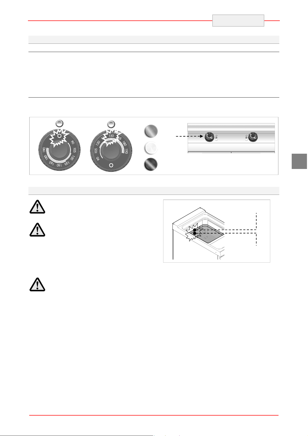
5.1. Description of the controls .
The elements controlling the essential functions
are located on the control panel of the appliance.
A) Temperature control: to switch the
heating coils on and off.
B) Green control: indicates the power
supply on.
A
Position ZERO
Operational temperature
C) White control: indicates that the deep
foyer is being heated.
D) Red control: indicates the safety
thermostats on.
Control
A
A
C
D
6
B
5.2. Switch the appliance on and off
ON
1. Start the automatic switch-off to turn on
the electrical connection.
2. Fill up the container.
3. Set the A control at the desired position.
The green control (B) is on. The white
OFF
1. To switch off the electric heating coils set
the knob A at the 0 position. The control
(B) is off.
ENGLISH
control C indicates heating up the oil.
When the oil reaches the required
temperature the white control C is off.
2. Start the automatic switch-off to turn off
the electrical connection.
A
C
5.3. Filling up the container
Before filling up the container check that
the outlet valve A is closed.
Avoid using the appliance with the
container filled up with the oil below the marked
minimum level.
We advise against the use of the appliance
with the container filled up with the oil above the
marked maximum level.
Never switch on the heating coils if there
is no oil in the container. The appliance may be
totally damaged.
D
GB
Max. level
Min. level
7

ENGLISH
5.4. Draining the container
Before draining the container, leave the
appliance to cool down so that the oil is cold.
When draining the container follow the
instructions below:
A. Open the door
B. Check that the oil container (B) is placed
correctly under the outlet valve
C. Open the outlet valve (A)
D. Close the outlet valve (A) as soon as the oil
container is full.
E. Remove the oil container (B)
F. Close the door.
B
Dispose the oil in accordance with the
regulations binding in the where the appliance is
in use.
GB
A
B
CLOSED
OPEN
5.5. Guidelines on how to use the appliance
Longer interval in the use of the appliance
When you plan not to use the appliance for the
prolonged time, follow the instructions below:
1. Turn on the automatic switch-off to disconnect
from the mains.
2. Thoroughly clean the appliance and
surrounding areas.
3. Apply the vaseline oil on the stainless steel
surfaces.
4. Perform all maintenance works;
5. Do not cover the appliance and leave the
container open.
When finished using the appliance, always
empty the container.
Guidelines on regular use of the appliance
To ensure the correct use of the appliance, follow
the guidelines below:
Use exclusively the accessories provided by
the manufacturer;
Use the frying baskets in the correct way;
Before filling up the container, check that the
outlet valve is closed;
Make sure that the oil level is not below the
minimum level marked in the container;
Before immersing the basket, check that the
oil has reached the set temperature.
Slowly immerse the basket to avoid excessive
foam formation.
Frequently filter the oil.
During the short breaks lower the temperature
to reduce the oil consumption and slow down
ageing the oil.
8

We recommend the change of oil when its
colour is darker or when at the temperature
160 °C - 180 °C the smoke is forming. The old
oil has a low ignition temperature.
Remember that the foods that are too moist or
the load that is too high may cause the oil to
boil unexpectedly.
oil in the container. It may cause total
damage to the appliance.
When heating up the deep fryer, always
remove the lid.
6. CLEANING AND MAINTENANCE
6.1. Guidelines on cleaning and maintenance
particular, disconnect the electric power supply by
Before you start maintenance works, turn
on all the mounted protective devices. In
6.2. Correct maintenance (service technician)
The correct maintenace covers everyday clearing
of all the elements that are in contact with foods.
Careful maintenance ensures the best
performance, longer life of the appliance and
proper operation of the protective devices.
Never direct the water stream or high pressure jet
towards the appliance.
To clean the stainless steel, do not use iron wool
or iron brush as they may leave iron particles on
the surface that form rust in result of oxidation.
Use the wooden or plastic spatula, or soft
cleaning sponge to remove the dried remains.
6.3. Cleaning the container
Follow the guidelines.
Turn off the appliance and leave to cool down.
Turn on the switch-off to disconnect from the
electrical supply.
Empty the container and filter the oil.
Remove and clean the frying baskets and
basket handles (A).
Place the heating coils (B) in the vertical
position.
Clean the container inside using the cleaning
agent intended for contact with foods.
Rinse off with water and empty the container.
means of the automatic switch-off.
In the case of prolonged intervals in the use of the
appliance, apply the vaseline oil onto all the
stainless steel surfaces.
contain substances hazardous or harmful to
health (solvents, petrol. etc.).
At the end of the working day clean:
container
frying baskets and other accessories
appliance.
Regularly instruct the specialist personnel to
perform the following maintenance works:
check the electric installation;
check the safety thermostats.
To remove the remaining cleaning agent the
Rinse off, empty and dry out the container.
When finished using the appliance, clean the
Place the heating coils (B) in the horizontal
ENGLISH
Never use the appliance without the
Do not use any clearing agents that
container can be sprinkled with a special
agent or vinegar and water solution.
elements with a proper agent to solve the fat.
We recommend to wash the accessories in
the dishwasher.
position (operating position).
GB
9

A
ENGLISH
GB
7. TROUBLESHOOTING
The information below is provided to recognize
and repair any failures that may occur when
operating the appliance. Some of the failures can
Problem Cause Solution
The electrical connection is not
correct.
The heating coils do not heat
up.
Safety thermostats are on.
Damaged heating coils switch.
B
be repaired by the user, others require thorough
specialist knowledge. Such problems may be
solved exclusively by the qualified personnel.
Horizontal
position
Check the electrical connection.
Reset the appliance (see the special
chapter).
Change the switch.
Inform the customer services.
Vertical
position
10

THIS
SIDE UP
8. INSTALLATION
8.1. Packaging and unpacking
During unloading and when installing the
appliance follow the information from the
manufacturer placed directly on the packaging
and in this manual.
To lift and transport the product plan to use a fork
lift or stacker, and pay attention to even weight
distribution to avoid a risk of tilting of the
packaging (avoid excessive incline!).
When using the lifting equipment pay
attention to the mains cable, water supply and
discharge pipes and feet position.
The packaging consists of the carton packaging
and wooden pallet. There are symbols printed on
the carton packaging that according to the
international agreements inform about the
regulations to follow when loading and unloading,
transporting and storing the appliance.
ENGLISH
When collecting the goods check if the packaging
is complete and has not been damaged during
transport.
Any damage should be immediately reported to
the shipping company.
Unpack the appliance as soon as possible to
check if the appliance is not damaged.
Do not use a sharp object to cut the carton box. It
may damage the stainless steel inside the box.
Remove the carton packaging from bottom to top.
When unpacked check if the appliance is
according to the order.
In case of any difference inform the sales agent
immediately.
GB
Do not store the packaging materials
(nylon bags, polystyrene foam, clips ...) in the
reach of children!
Remove the protective PVC layer from the out
and inner surfaces. If possible, do not use any
metal tools.
FRAGILE KEEP DRY
8.2. Installation (service technician)
All the stages of the installation must be carefully
planned.
The location should be equipped with all supply
connections and production waste outlet. The
location should also be properly lit and comply
with all hygiene and sanitary requirements
according to the binding regulations.
The appliance should be installed with the
minimum 5 cm clearance from the wall, if the wall
is not resistant to the minimum temperature of
150°C.
Locate the appliance in the horizontal position by
adjusting the single feet.
To ensure the correct operation of the
appliance, the appliance must be installed and
operated in the thoroughly ventilated room only.
50
11

B
C
A
M
ENGLISH
8.3. Connection to the mains (service technician)
The appliance may be connected to the mains
exclusively by the authorized and qualified
personnel and when the binding regulations are
observed and when the proper material is used in
accordance to the regulations.
The appliance is built to use the following power
(see the attached table):
380-415V 3N~ 50-60Hz
220-240V 3~ 50-60Hz
GB
To prevent any risks the damanged supply
cable may be exchanged only by the
manufacturer or expert.
The correct cross section of the cable is
presented in the attachments and should be
decided by the electrician.
To correctly connect the appliance, follow the
following guidelines.
Remove the cover from term block (A).
Connect the switch-off to the term block (B) of
the appliance, as shown in the drawing and
block diagram (see the attachment).
Preferably use cable H07RN-F type or better,
which is resistant to high temperature min. up
to 80°C.
Tighten the cable endings (C).
Place the cover on the term.
The appliance is equipped with the equipotential
clamp (M).
Respectively to the clamp used a special sticker is
envisaged:
8.4. Installation of the appliance in a line
To fix the appliance in a line (neighbouring) follow
the steps:
1. Dismantle the control panel, and remove the
cast iron frame from the chimney if necessary.
2. Apply the sealing tape (A) onto the joining
sides.
12
3. Place the appliances next to each other and in
a horizontal position (by adjusting the feet).
4. Connect the appliances with the joining
elements.
5. Remove the excess of the sealant.

A
A
ENGLISH
8.5. Check-up
Before starting the appliance the installation
check-up should be run to evaluate the working
conditions of every single component and
recognize any errors.
It is recommended to run the following check-ups:
9. SETTINGS
There are no special default settings of the
appliance. The only settings are those set up by
the user while using the appliance.
10. APPLIANCE DISPOSAL
1. Check that the energy supply voltage is the
same as of the appliance voltage.
2. Turn on the automatic switch-off to check the
electrical connections.
3. Check that the protection devices work
correctly.
GB
The appliance is marked in conformity with
the European Directive 2002/96/EG WASTE
ELECTRICAL AND ELECTRONIC EQUIPMENT
(WEEE).
By disposing the appliance in accordance
with the regulations the user contributes towards
prevention of adverse effects on environment and
health.
The symbol on the product or
attached manual indicates that the product cannot
be considered as ordinary household waste and
should be transferred to a special collection point
for electrical and electronic appliances for
recycling.
Local waste management regulations should be
observed.
Further information on procedure, reusing and
recycling of the product is available in local
offices, waste management unit or with the
product sales agent.
13

ANLAGEN
ATTACHMENTS
ANNEXES
ALLEGATI
ANEXOS
ANEXOS
BIJLAGEN
ZAŁĄCZNIKI
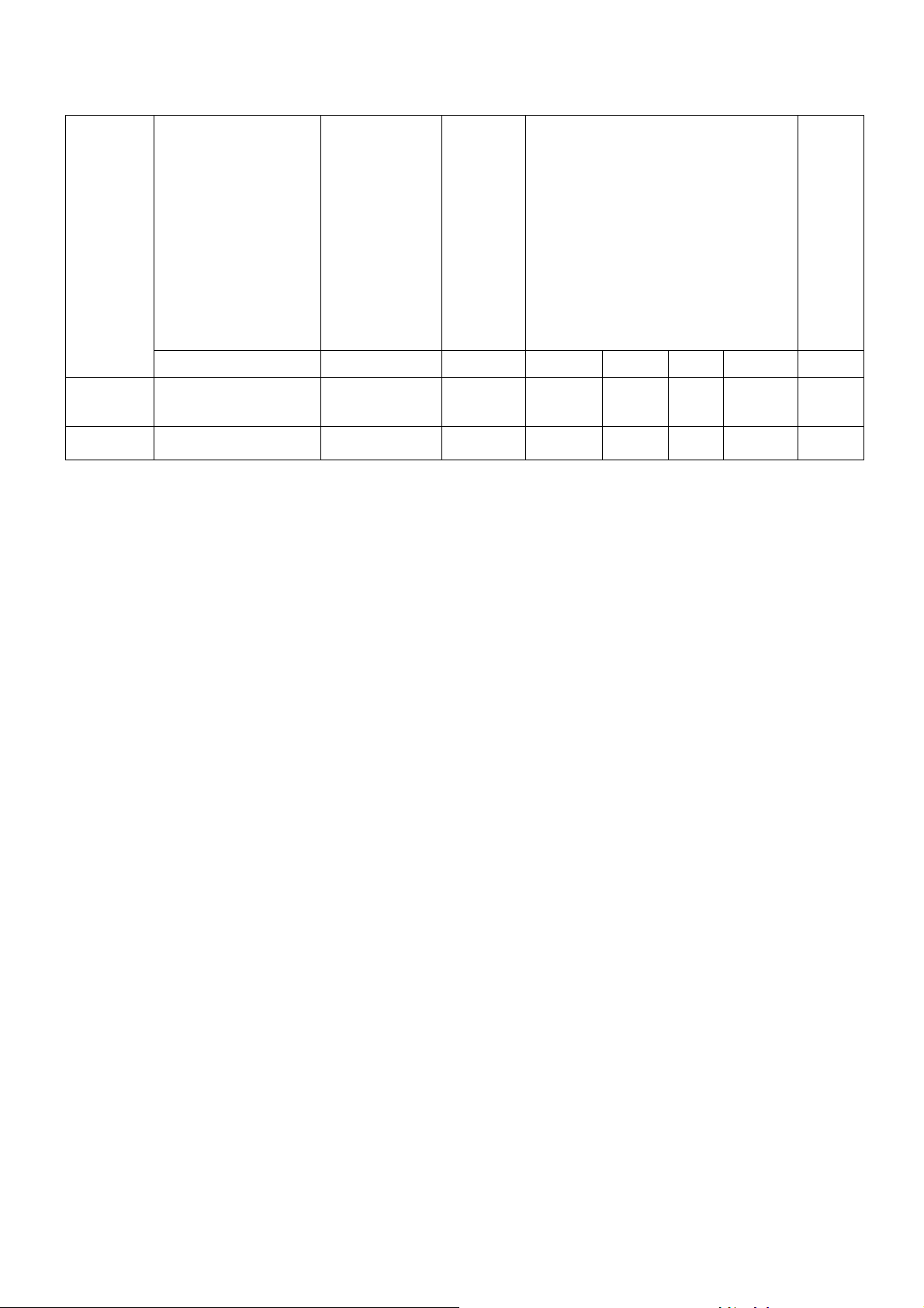
Modell
Model
Modèle
Modello
Modelo
Modelo
Model
Model
FRE91M00
FRE92M00
Beckeninhalt
Container capacity
Contenance du bac
Capacità del serbatoio
Capacidad del tanque
Capaidade do depósito
Inhoud van de bak
Pojemność zbiornika
L (l)
21 2,2 17,4
2 x 21 2,2 + 2,2 34,8
Einfüllmenge
Load
Quantité à remplir
Quantità da
riempire
Cantidad a llenar
Quantidade para
preencher
Inhoud voor het
invullen
Ilość do
napełniania
Leistung
Power
Puissance
Potenza
Potencia
Potência
Vermogen
Moc
Electrical connection
Raccordement électrique
Dati relativi all’impianto elettrico
Datos de instalación eléctrica
Dados para a instalação elétrica
Gegevens van de elektrische installatie
Dane dot. instalacji elektrycznej
kg kW V Hz A
380-415V
3N~
380-415V
3N~
Daten zu Elektrik
25,2
50-60
50-60 25,2
+
25,2
Kabel
5 x 2,5
mm2
5 x 2,5
mm2 (2x)
Gewicht
Weight
Poids
Peso
Peso
Peso
Gewicht
Ciężar
kg
68
86

ANSCHLUSSSCHEMA
FRE91M00
- CONNECTION CARD - FICHE DES RACCORDEMENTS -
SCHEDA ALLACCIAMENTI - FICHA DE ENLACES - ESQUEMA DAS CONEXÕES -
PLAN AANSLUITINGEN - SCHEMAT PODŁĄCZENIA
Elektroanschluss
Electric Connection
Branchement Electrique
Allacciamento Elettrico
Conexiòn elètrica
Ligação Elétrica
Elektrische aansluiting
Przyłącze elektryczne
380-415V
3N~
50/60 Hz
220-240V
3~
50/60 Hz

ANSCHLUSSSCHEMA
FRE92M00
SCHEDA ALLACCIAMENTI - FICHA DE ENLACES - ESQUEMA DAS CONEXÕES -
PLAN AANSLUITINGEN SCHEMAT PODŁĄCZENIA
- CONNECTION CARD - FICHE DES RACCORDEMENTS -
Elektroanschluss
Electric Connection
Branchement Electrique
Allacciamento Elettrico
Conexiòn elètrica
Ligação Elétrica
Elektrische aansluiting
Przyłącze elektryczne
380-415V
3N~
50/60 Hz
220-240V
3~
50/60 Hz

111
61308
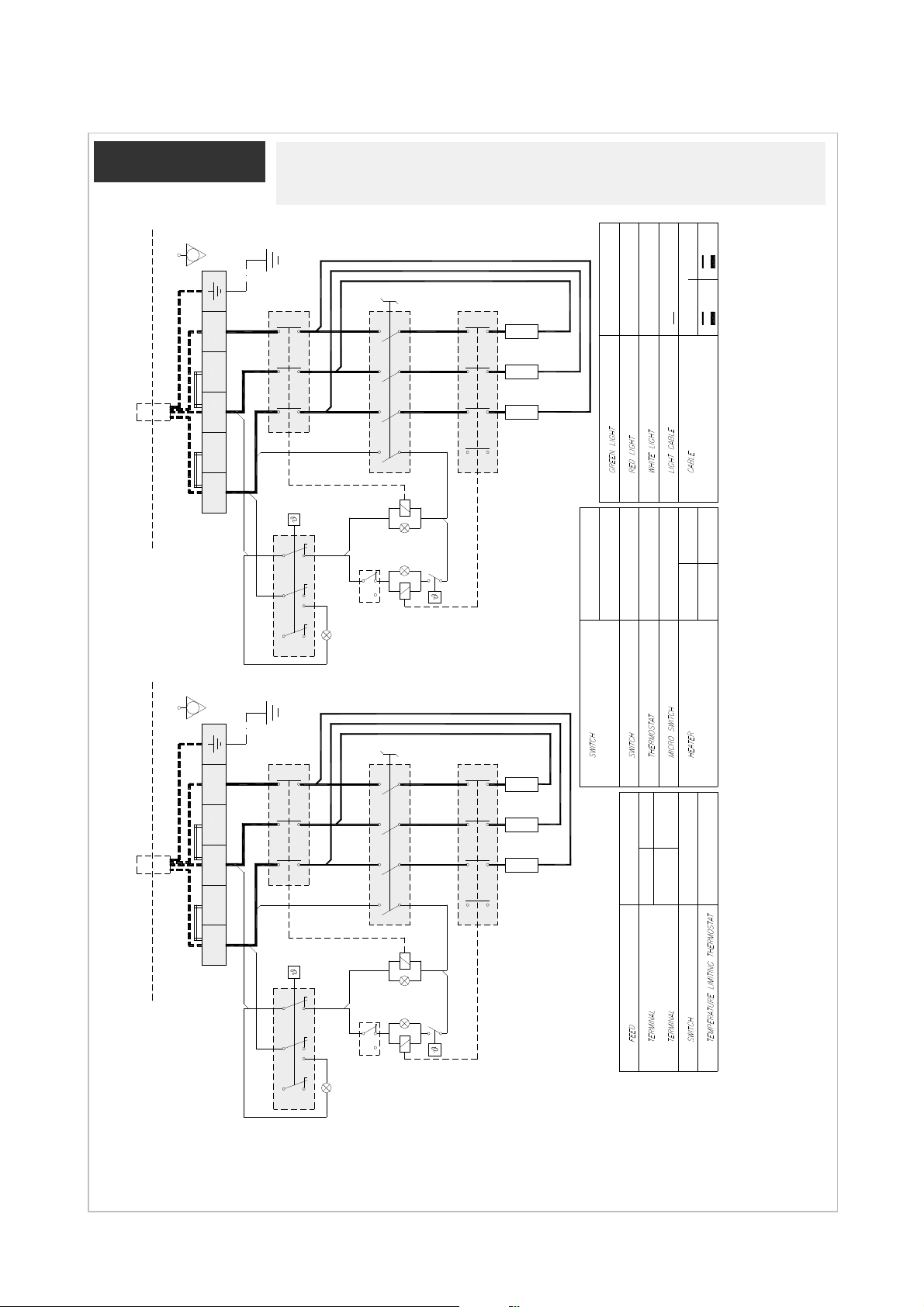
SCHALTPLAN
REVISION 03
- ELECTRIC DIAGRAM – SCHÉMA ÈLECTRIQUE -
SCHEMA ELETTRICO - ESQUEMA ELÉCTRICO -
ELEKTRISCH SCHEMA - SCHEMAT IDEOWY
K
7
±
C
190
1
8
0
1
6
5
150
B1
1
3
5
1
2
0
0
9
105
49.41832.030
4 3 2 1
P4 P3 P2 P1
0 35°-318°
4 3 2 1
P4 P3 P2 P1
PE
B1
P2P1P3P4
3215
S1
°
5
9
230V 25.2A
5800 watt (3x)
J7KN24
OMRON
OMRON
95°C - 190°C
J7KN-22D-10
ALLEN BRADLEY
T1
190°C ±5K
55.19035.800
100-C16(10) 32A AC1
C1 = CONTATTORE
PANASONIC
AM51614C53N
700 17L 900
EGO 55.19035.800 0.5A
MCR = MICROINTERRUTTORE
T1 = TERMOSTATO
230V 20.3A
4667 watt (3x)
R1,R2,R3 = RESISTENZE
C1
R3R2R1
Section 1 mmq
CAVO H05SJ-K
Section 4 mmq
24
L1 L2 L3 N N
M2
11 21 31
12 22 32
14 2 4 6
13 1 3 5
M2 M2 M2
(T120) Silicon Leads
SIGNAL LUX Mod 21.3 230V
CAVO H05SJ-K
(T120) Silicon Leads
(T120) Silicon Leads
SIGNAL LUX Mod 21.3 230V
SIGNAL LUX Mod 21.3 230V
M1
LV
A1
PE
1
MCR
FRE91 : 5G x 4mmq In=25.2 A FRE92 : 5G x 4mmq In=25.2 A
FRE71 17L : 5G x 4mmq In=20.3 A FRE72 17L : 5G x 4mmq In=20.3 A
P2P1P3P4
L1 L2 L3 N N
M1
380-415V 3N~ 50-60Hz 380-415V 3N~ 50-60Hz
A2
3.
B1
3215
T1
LB
LR
S1
C1
R3R2R1
24
11 21 31
12 22 32
14 2 4 6
13 1 3 5
M2 M2 M2
LB = LAMPADA BIANCA
LR = LAMPADA ROSSA
LV = LAMPADA VERDE
380-415V 3N~ 50-60Hz
CABLAGGIO
CABLAGGIO LAMPADE
43.41832.030
55.32545.090
4 Poli 32A 250V T150
FV122 6 POLI - 40 A - 450 V
T=235°C 16K 400V 30A
FV122 6 POLI - 40 A - 450 V
M1
LV
A1
A2
1
3.
MCR
T1
LB
LR
ALIMENTAZIONE
B1 = COMMUTATORE
M1 = MORSETTIERA SX
S1 = LIMITATORE DI TEMPERATURA
M2 = MORSETTIERA DX
111
61308
SCHALTPLAN
REVISION 03
- ELECTRIC DIAGRAM – SCHÉMA ÈLECTRIQUE -
SCHEMA ELETTRICO - ESQUEMA ELÉCTRICO -
ELEKTRISCH SCHEMA - SCHEMAT IDEOWY
4mmq
PE
10mmq
C2
6
5
FRE72-17L : 4G x 6 mmq In=35.1 A
FRE92 : 4G x 10 mmq In=43.7 A
1 3
2 4
B1
P2P1P3P4
3215
L1 L1 L2 L2 L3
A1
M2
S1
220-240V 3~ 50-60Hz
31
24 32
11 21
12 22
1
LR
A2
LV
LB
3.
A1
A2
MCR
C1
(T120) Silicon Leads
SIGNAL LUX Mod 21.3 230V
SIGNAL LUX Mod 21.3 230V
R3
6
5
CESUP INF
R2R1
14 2 4
13 1 3
T1
SIGNAL LUX Mod 21.3 230V
LR = LAMPADA ROSSA
LV = LAMPADA VERDE
J7KN24
OMRON
OMRON
OMRON
J7KN-22D-10
Section 1 mmq
CAVO H05SJ-K
CAVO H05SJ-K
6mmq
(T120) Silicon Leads
(T120) Silicon Leads
SIGNAL LUX Mod 21.3 230VEGO 55.19035.800 0.5A
LB = LAMPADA BIANCA
J7KN24
95°C - 190°C
4mmq
700 17L 900
CABLAGGIO
CABLAGGIO LAMPADE
230V 25.2A
5800 watt (3x)
PANASONIC
AM51614C53N
700 17L 900
230V 20.3A
4667 watt (3x)
PE
C2
L3
FRE71-17L : 4G x 6 mmq In=35.1 A
FRE91 : 4G x 10 mmq In=43.7 A
6
5
1 3
2 4
B1
P2P1P3P4
3215
C1
R1,R2,R3 = RESISTENZE
MCR = MICROINTERRUTTORE
C2 = CONTATTORE
R3
6
5
CESUP INF
R2R1
14 2 4
13 1 3
C1 = CONTATTORE
T1 = TERMOSTATO
WDU10mmq
WEIDMULLER
55.32545.090
43.41832.030
220-240V 3~ 50-60Hz
700 17L 900
4 Poli 32A 250V T150
T=235°C 16K 400V 30A
40 A - 450 V
FV122 6 POLI
L1 L1 L2 L2
A1
M1
S1
220-240V 3~ 50-60Hz
31
24 32
11 21
12 22
1
LR
A2
LV
LB
3.
T1
A1
A2
M1 = MORSETTIERA SX
M2 = MORSETTIERA DX
ALIMENTAZIONE
B1 = COMMUTATORE
S1 = LIMITATORE DI TEMPERATURA
MCR

NOTE

DE
LAUT GESETZLICHER VORSCHRIFT STEHT DIESES HANDBUCH UNTER EIGENTUMSVORBEHALT UND DARF AUS DIESEM GRUND NICHT OHNE UNSERE GENEHMIGUNG
VERVIELFÄLTIGT UND/ODER IN JEGLICHER FORM AN DRITTE WEITERGEGEBEN WERDEN!
GB
IN COMPLIANCE WITH THE LAW IN FORCE,IT IS PROHIBITED TO REPRODUCE AND/OR
DISTRIBUTE THIS MANUAL IN ANY WAY WITHOUT THE AUTHORISATION OF THE PROPRIETOR!
FR
AUX TERMES DE LA LOI, LA PROPRIETE DE CETTE NOTICE EST RESERVEE. IL EST DONC
INTERDIT DE LA REPRODUIRE ET/OU DE LA DISTRIBUER SOUS QUELQUE FORME QUE CE SOIT
SANS NOTRE AUTORISATION!
IT
A TERMINI DI LEGGE È RISERVATA LA PROPRIETÀ DI QUESTO MANUALE CON DIVIETO DI
RIPRODURLO E/O DISTRIBUIRLO IN QUALSIASI FORMA SENZA NOSTRA AUTORIZZAZIONE!
ES
DE ACUERDO CON LOS TÉRMINOS DE LA LEY ESTÁ RESERVADA LA PROPIEDAD DE ESTE
MANUAL CON EXPRESA PROHIBICIÓN DE REPRODUCIRLO Y /O DISTRIBUIRLO EN CUALQUIER
FORMA SIN NUESTRA AUTORIZACIÓN!
PT
A PROPRIEDADE DESTE MANUAL É RESERVADA POR LEI, SENDO PROIBIDA A SUA
REPRODUÇÃO E/OU DISTRIBUIÇÃO EM QUALQUER FORMA SEM A NOSSA AUTORIZAÇÃO!
NL
DE FABRIKANT BEHOUDT ZICH HET RECHT VOOR OM DE KENMERKEN VAN DE
TOESTELLEN DIE IN DEZE PUBLICATIE WORDEN VOORGESTELD TE WIJZIGEN ZONDER
VOORAF TE VERWITTIGEN!
PL
ZGODNIE Z PRZEPISAMI PRAWNYMI NINIEJSZA INSTRUKCJA JEST NASZĄ WŁASNOŚCIĄ
I Z TEGO POWODU NIE MOŻE BYĆ BEZ NASZEJ ZGODY POWIELANA I / LUB PRZEKAZYWANA
W JAKEJKOLWIEK FORMIE OSOBOM TRZECIM!
 Loading...