


GAS-NUDELKOCHER
GAS PASTA COOKER
CUISEUR À PÂTES À GAZ
CUOCIPASTA A GAS
COCEDOR DE PASTA GAS
2953031 / CPG91M01
MÁQUINA DE MACARRÃO, GAS
GAZ PASTAKOKER
URZĄDZENIE DO GOTOWANIA
PRODUKTÓW MĄCZNYCH, GAZOWE
DE
GB
FR
IT
ES
PT
NL
Rev.-Nr.: 01-2017
IN ST AL LA TI ON S- , BE DI EN UN GS UN D WART UN GS ANWEISUNGE N
IN ST AL LA TI ON , OP ER AT IN G
AN D MA IN TE NA NC E NS TR UC TI ON S
MA NU EL D'I NS TALL AT IO N,
D' UT IL IS AT IO N ET D'E NT RE TI EN
MA NU AL E DI I NS TA LL AZIO NE ,
US O E MA NU TE NZ IO NE
MA NU AL DE IN ST AL AC IÓ N,
US O Y MA NT EN IM IE NT O
MA NU AL DE IN ST AL AÇ ÃO ,
UT IL IZAÇÃO E MANUT ENÇÃ O
HA ND LE IDING VO OR INSTALLAT IE ,
GE BR UI K EN O ND ERHO UD
W SKA ZÓ WK I DO TYCZĄCE I NS TA LA CJ I,
UŻ YT KO WANI A I KO NS ER WACJI
PL

DE
TECHNISCHE ÄNDERUNGEN VORBEHALTEN!
GB
TECHNICAL CHANGES RESERVED!
FR
SOUS RÉSERVE DE MODIFICATIONS TECHNIQUES !
IT
CI RISERVIAMO LA POSSIBILITÀ DI INTRODURRE MODIFICHE TECNICHE!
ES
¡SE RESERVA EL DERECHO A INTRODUCIR MODIFICACIONES TÉCNICAS!
PT
SUJEITO A ALTERAÇÕES TÉCNICAS!
NL
TECHNISCHE WIJZIGINGEN VOORBEHOUDEN!
PL
WPROWADZANIE ZMIAN TECHNICZNYCH ZASTRZEŻONE!

ENGLISH
1. TABLE OF CONTENTS
1. TABLE OF CONTENTS ..................................................................................................................... 1
2. INDEX ................................................................................................................................................. 2
3. SAFETY .............................................................................................................................................. 3
4. GENERAL INFORMATION AND WARNINGS ................................................................................... 4
4.1. General guidelines ................................................................................................................... 4
4.2. Description of the appliance ..................................................................................................... 4
4.3. Protection appliances ............................................................................................................... 5
4.4. Rating plate .............................................................................................................................. 6
4.5. Replacement of components (service technician) ................................................................... 6
5. USE AND OPERATION ..................................................................................................................... 7
5.1. Description of the controls . ...................................................................................................... 7
5.2. Burner ignition .......................................................................................................................... 7
5.3. Filling the tank .......................................................................................................................... 8
5.4. Draining the container .............................................................................................................. 8
5.5. Guidelines on how to use ......................................................................................................... 8
6. CLEANING AND MAINTENANCE ..................................................................................................... 8
6.1. Guidelines on cleaning and maintenance ................................................................................ 8
6.2. Proper maintenance ................................................................................................................. 9
7. TROUBLESHOOTING ..................................................................................................................... 10
8. INSTALLATION ................................................................................................................................ 10
8.1. Packaging and unpacking ...................................................................................................... 10
8.2. Installation (service technician) .............................................................................................. 11
8.3. Water connection (service technician) ................................................................................... 11
8.4. Gas connection (service technician) ...................................................................................... 12
8.5. Extraction of fumes (service technician) ................................................................................ 12
8.6. Installation of the appliance in a line ...................................................................................... 13
8.7. Gas supply (service technician) ............................................................................................. 13
8.8. Inspection (service technician) ............................................................................................... 13
9. SETTINGS ........................................................................................................................................ 14
9.1. Minimum setting of burner valve (service technician) ............................................................ 14
9.2. Replacement of burner nozzle (service technician) ............................................................... 14
9.3. Replacement of igniting flame burner nozzle (service technician) ......................................... 15
10. APPLIANCE DISPOSAL .................................................................................................................. 15
ATTACHMENTS ....................................................................................................................................... I
GB
1

ENGLISH
2. INDEX
GB
A
APPLIANCE DISPOSAL 15
B
Burner ignition 7
D
Description of the appliance 4
Description of the controls 7
Draining the container 8
E
Extraction of fumes 12
F
Filling the tank 8
G
Gas connection 12
Gas supply 13
General guidelines 4
Guidelines on cleaning and maintenance 8
Guidelines on how to use 8
M
Minimum setting of the heating plate burner
valve. 14
P
Packaging 10
Proper maintenance 9
Protection appliances 5
R
Rating plate 6
Replacement of burner nozzle 14
Replacement of components 6
Replacement of igniting flame burner nozzle 15
S
SAFETY 3
T
TROUBLESHOOTING 10
U
Unpacking 10
I
Inspection 13
Installation 11
Installation of the appliance in a line 13
W
Water connection 11
2

3. SAFETY
Read carefully the guidelines and
instructions in the instruction manual
before you use the appliance.
The instruction manual contains general
information on how to safely use and maintain the
appliance.
Retain the manual for future reference.
The manufacturer took extra care when designing
and manufacturing to prevent any safety or health
hazard to the personnel operating the appliance.
Please read carefully the guidelines in the
instruction manual and instructions placed directly
onto the appliance. Above all, observe all the
safety instructions.
Do not intervene in or remove the protective
appliances installed in the appliance. Noncompliance may lead to severe safety and health
hazard against people. We recommend to perform
a few tests to know the layout and main functions
of the control panel, particularly those to switch
the appliance on and off.
The appliance is intended only for the use it has
been designed for and any other use is
considered as the use not in compliance with the
intended use.
The manufacturer is not liable for material
damage or damage to person caused by
misapplication or incorrect application of the
appliance.
ENGLISH
Any maintenance work that requires special
technical licence or special skills may be
performed by qualified personnel only.
To provide hygiene and protect foods from dirt, all
the elements that have direct or indirect contact
with the foods and all border areas must be
thoroughly cleaned. Use only the cleaning agents
intended for use in contact with food and avoid
using flammable agents or harmful to health.
After each use make sure that the
burner is switched off, the operational
elements are deactivated, and the gas
supply hoses are disconnected.
When the device will not be used for a longer time
not only disconnect all gas supply hoses, but also
thoroughly clean all internal and external elements
of the device.
You must not clean the appliance
with the direct stream of water.
GB
3

GB
4
ID 01
ENGLISH
4. GENERAL INFORMATION AND WARNINGS
4.1. General guidelines
The manual has been edited by the manufacturer
to provide the authorized personnel with the
information necessary to work with the appliance.
We recommend the intended readers to read the
manual carefully and comply with the information.
By reading the information contained in the
manual, hazards against people health and safety
may be prevented.
Retain the manual in an easily available place
throughout the time of use of the appliance to
have access and refer to the required information
at any time.
4.2. Description of the appliance
This appliance, called pasta cooker, has been
designed and manufactured for professional
gastronomy for cooking flour food products in
water.
1) Container
2) Door
3) Feet of adjustable height
4) Gas connection
5) Extractor: Extraction of combustion gases
6) Water valve: Fills and adjusts water
amount in the container.
7) Power control knob: adjusts burner power
(min - max)
8) Burner ignition: piezoelectric burner
ignition
9) Water inlet: fills container with water:
10) Minimum and maximum water level in the
container.
Special symbols, described below, have been
used to stress important information or draw
attention to essential data:
Caution - warning
Indicate important safety
instructions. You should acquire the
proper conduct to prevent hazard against
people health and safety or not to cause
any damage.
Important
Indicate essentials technical data that
you cannot ignore.
5
9
10
1
6
8
7
2
3
4

4.3. Protection appliances
The appliance is equipped with the protection
system. The arrangement of protection appliances
is presented on the drawing.
A) Gas cut-off valve: to open and close the gas
line.
B) Safety thermocouple: cuts off the gas supply
if the flame goes out.
C) Safety thermostat: cuts off gas supply when
there is no water.
Check every day that the protection
appliances are mounted correctly and
operational.
After releasing of the safety thermostat restore the
initial settings of the appliance.
1. Wait for the unit to cool.
2. Open the door (D).
3. Press the safety thermostat button (B) to
reactivate the gas supply.
4. Close the door (D).
ENGLISH
C
C
GB
After releasing of the safety thermostat
press button (C).
D
B
A
5

GB
5
6
7 8
9
ENGLISH
4.4. Rating plate
The rating plate indicated in the drawing is
mounted directly onto the appliance. There are all
guidelines and information on the plate required
for safe use.
1) EAN number
2) Code no./ Model no. / CE certificate no.
3) Category of appliance / type of design
2
3
4
4) Connected value / gas consumption /
adjusted to gas type
5) Thermal load
6) Production date
7) Series no.
8) WEEE symbol
9) CE Declaration of Conformity
1
4.5. Replacement of components (service technician)
If necessary, exchange the used components to
Before exchange of the component
switch on all the existing protection
appliances.
First of all, switch off the gas valve and
prevent access to the appliance, which in
the case of activation may lead to
unexpected situations endangering the
safety and health of people.
the original spare parts.
We are not liable for personal injury or
damage to the components that arise due to
application of other spare parts than original
or intervention into the appliance without the
manufacturer’s consent that may have altered
the safety requirements.
6
B
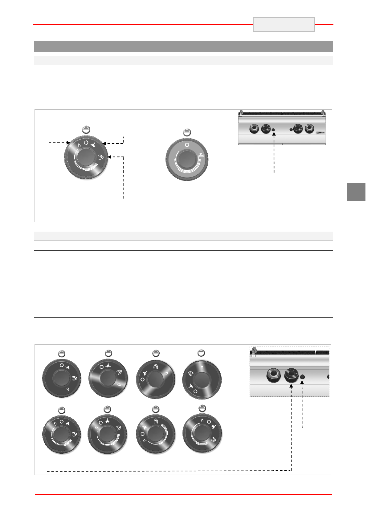
5. USE AND OPERATION
5.1. Description of the controls .
The elements controlling the essential functions
are located on the control panel of the appliance.
A) Burner control knob: for igniting, putting
out, and adjusting the main burner.
B) Water valve: for filling the tank.
ENGLISH
C) Piezoelectric ignition: for starting the
igniting flame of the burner.
A
Minimum
power symbol
Flame icon
Maximum
power symbol
5.2. Burner ignition
IGNITION
A) Press the burner control knob and rotate it
counter clockwise (position 1); at the
same time press button B to start the
igniting flame.
B) Hold the control knob B pressed for
approx. 10 seconds in order to heat up
SWITCHING OFF
A) To switch off the burner rotate the control
knob clockwise (position 1); the igniting
flame is still on.
Water valve
Piezoelectric
C
the thermal element; then release the
controller.
C) To ignite the burner rotate the control
knob clockwise (position 2).
D) Set the burner power (position 3).
B) To switch off the igniting flame rotate the
control knob clockwise (position 0).
ignition
GB
22S
B
22R
Pos 0
Pos 1
Pos 2
Pos 3
7

ID 05
Maximum
level
Minimum
level
ENGLISH
5.3. Filling the tank
Rotate the water valve to fill the tank to the
required level. After reaching the maximum level
the burner may be ignited.
After filling close the water valve to avoid
dangerous overfilling.
When water level drops below minimum open the
water valve again.
The appliance may be connected to hot water
supply to reduce the heating time (max. 60°C).
When the water level drops below the
basket bottom, the safety thermostat may trip:
Fill the tank at least to the minimum level and
reignite the burner.
Avoid using the appliance with the
tank filled below the marked minimum
level.
GB
Pos. 0
Pos. 1
5.4. Draining the container
Water may be drained with use of appropriate
container resistant to temperature of min. 100°C.
To drain the tank rotate the drain valve A down.
Before filling up the container
check that the outlet valve A is closed.
5.5. Guidelines on how to use
When the appliance will not be used for a longer
time, follow the instructions below:
1. Close the gas cut-off valve.
2. Thoroughly clean the appliance and adjacent
surfaces.
3. Apply the food grade vaseline on the stainless
steel surfaces.
4. Perform all maintenance works.
5. Leave the appliance uncovered, with opened
cooking chambers.
Always empty the containers
after use.
A
CLOSED valve
To ensure correct use of the appliance follow the
guidelines below:
Use only accessories provided by the
manufacturer;
Use baskets in the correct way;
Before filling the tank check if the drain valve
is closed;
Make sure that the water level is above the
minimum level marked in the tank.
Never use the appliance without
OPENED valve
water in the tank. It may cause total
damage of the appliance.
8

6. CLEANING AND MAINTENANCE
6.1. Guidelines on cleaning and maintenance
First of all, close the gas valve and
Before you start maintenance
works, turn on all the mounted protective
appliances.
6.2. Proper maintenance
Proper maintenance includes daily cleaning of all
components which have contact with food
products, and regular maintenance of the burner,
nozzle and exhaust pipes.
Thorough maintenance allows for obtaining the
best results, assures longer life of the appliance,
and keeping constant level of the safety
requirements.
Never direct the water stream or high pressure jet
towards the appliance.
To clean the stainless steel, do not use iron wool
or iron brush as they may leave iron particles on
the surface that form rust in result of oxidation.
Use the wooden or plastic spatula, or soft
cleaning sponge to remove the dried remains.
When the appliance will not be used for a longer
time, use cloth soaked in food grade vaseline to
apply the protective layer on all stainless steel
surfaces and ventilate the room periodically.
prevent access to the appliance, which in
the case of activation may lead to
unexpected situations endangering the
safety and health of people.
contain substances hazardous or harmful
to health (solvents, petrol. etc.).
Regularly instruct the specialist personnel to
perform the following maintenance works:
Installation pressure and tightness control;
Thermocouples functionality control;
Control of operation of the extractor and
Inspection and possible lubrication of gas
Control of correct operation of safety barostat.
ENGLISH
Do not use any clearing agents that
GB
possible cleaning;
valves.
9

THIS
CAUTION
ENGLISH
7. TROUBLESHOOTING
The information below is provided to recognize
and repair any failures that may occur when
operating the appliance.
Problem Cause Solution
The smell is sometimes
Gas smell.
The ignition flame does not start.
released when extinguishing
the flame.
The spark ignition does not
work.
Air in the pipes in connection
with the long downtime.
Some of the failures can be repaired by the user,
others require thorough specialist knowledge.
Such problems may be solved exclusively by the
qualified personnel.
Close the gas cut-off valve and
ventilate the room.
Check operation of ignition
appliances. Ignite the flame
manually.
Contact the service company.
GB
The igniting flame continuously
goes out.
Yellow flame.
It is difficult to rotate the burner
control knob.
The thermal element is not
sufficiently hot.
The burner is contaminated or
moist.
Damaged valve.
8. INSTALLATION
8.1. Packaging and unpacking
During unloading and when installing the
appliance follow the information from the
manufacturer placed directly on the packaging
and in this manual.
To lift and transport the product plan to use a fork
lift or stacker, and pay attention to even weight
distribution to avoid a risk of tilting of the
packaging (avoid excessive incline!).
Extend the ignition process.
Clean the burner and leave for
drying.
When problem persists contact
the service company.
Contact the service company.
The packaging consists of the carton packaging
and wooden pallet. There are symbols printed on
the carton packaging that according to the
international agreements inform about the
regulations to follow when loading and unloading,
transporting and storing the appliance.
While using the elevator pay
attention to the gas supply hoses and
position of feet.
KEEP DRY
SIDE UP
When collecting the goods check if the packaging
is complete and has not been damaged during
transport.
Any damage should be immediately reported to
the shipping company.
10
GLASS

ID 12
ID 06
Unpack the appliance as soon as possible to
check if the appliance is not damaged.
Do not use a sharp object to cut the carton box. It
may damage the stainless steel inside the box.
Remove the carton packaging from bottom to top.
When unpacked check if the appliance is
according to the order.
8.2. Installation (service technician)
All the stages of the installation must be carefully
planned.
The location should be equipped with all supply
connections and production waste outlet. The
location should also be properly lit and comply
with all hygiene and sanitary requirements
according to the binding regulations.
The appliance should be installed with the
minimum 5 cm clearance from the wall, if the
wall is not resistant to the minimum temperature
of 150 °C.
Locate the appliance in the horizontal position by
adjusting the single feet.
To ensure the correct operation of
the appliance, the appliance must be
installed and operated in the thoroughly
ventilated room only.
8.3. Water connection (service technician)
The installation is performed by connecting the
connection pipe of the appliance to the water
network pipe. Install the cut-off valve (A) on the
connection to stop the water supply when
required. Install appropriate filters after that valve.
ENGLISH
In case of any difference inform the sales agent
immediately.
Do not store the packaging
materials (nylon bags, polystyrene foam,
clips ...) in the reach of children!
Remove the protective PVC layer from the out
and inner surfaces. If possible, do not use any
metal tools.
Internal installation of the gas supply and the
rooms in which the appliance is housed, must
comply with the local regulations applicable in the
country in which the appliance is used (Regulation
of 12 June 96 and UNI-CIG 87/23).
In order to ensure the proper gas burning in the
burners the required volume of air, i.e. approx.
2 cubic meters per hour for every kW of installed
power, must be supplied.
Connect potable water to the
appliance. Limit values for the potable
water specified by the European Union are
listed in the table.
Description Value
Pressure 150-300 kPA
1.5-3 bar
pH 6.5-8
Hardness 8-15°F
(80-150 ppm CaCO3)
Minerals <1500 mg/l
Iron < 0.2 mg/l
Manganese <0.05 mg/l
Chlorine <0.25 mg/l
Sulphur <0.25 mg/l
GB
11

GB
ID 08
ENGLISH
8.4. Gas connection (service technician)
A gas connection must be performed in
compliance with the applicable regulations.
Before connecting the appliance, check the
technical data, type of gas, working pressure and
flow rate which are provided on the rating plate.
The installation is performed by connecting the
connection pipe of the appliance with a pipe of the
gas distribution network. A shut-off valve must be
installed on the connection to shut the gas supply
off if necessary.
If there are significant pressure differences in the
gas supply installation, it is recommended to
install a pressure regulator.
After the installation, check the gas connection for
tightness.
8.5. Extraction of fumes (service technician)
Installation of the type “A” appliances does not
envisage connection to the fume exhaust system,
but to the appropriate extraction hood which
discharges the fumes to outside.
Installation under the extraction hood (A)
Place the appliance under the extraction hood (1)
and attach to the appliance connection a pipe of
the size as shown on the figures.
The end of the fume extraction pipe should be
located at least 1.8m above the floor.
When looking for gas leaks do not
use the open flame!
The appliance's gas supply should
subordinated to the exhaust system:
Blocking of the fan must shut the gas
supply off.
The fan must switch on automatically when the gas valve is open.
12

A
A
B
C
C
ID 12
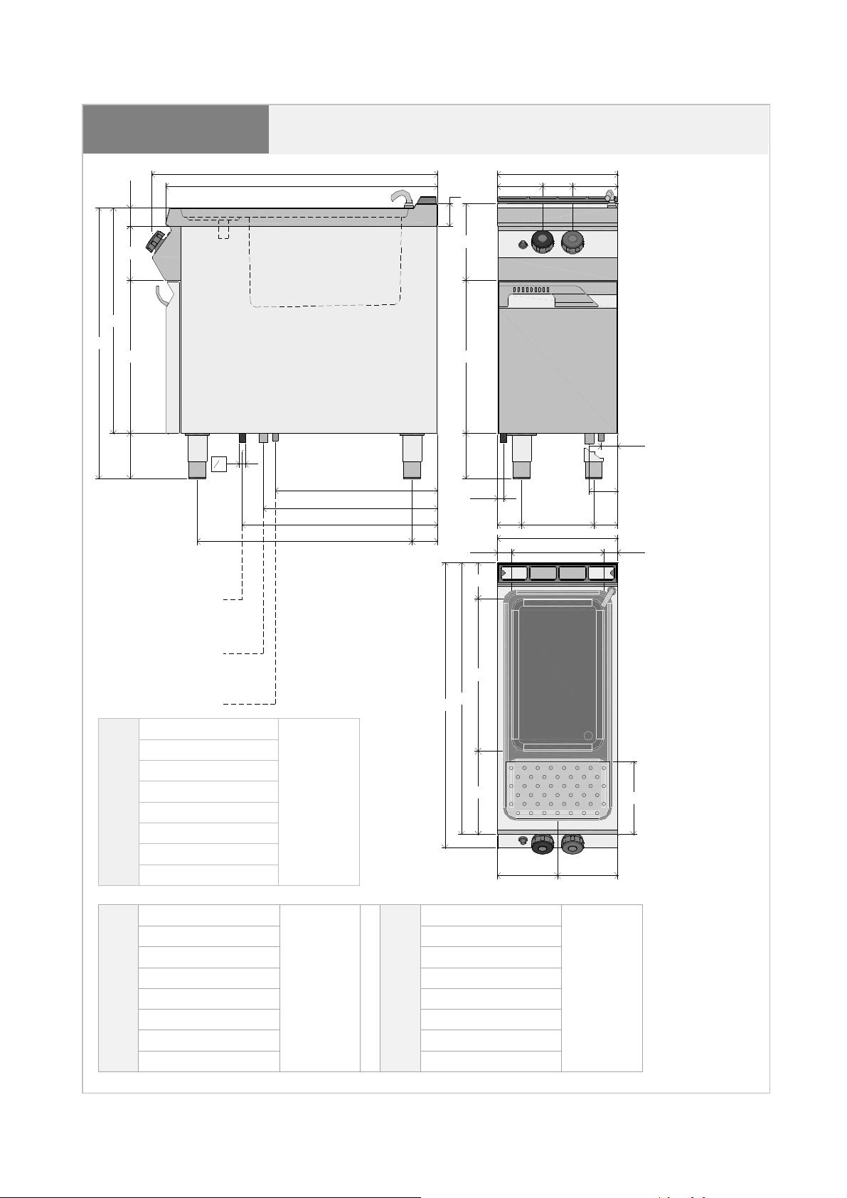
8.6. Installation of the appliance in a line
To fix the appliance in a line (neighbouring) follow
the steps:
Dismantle the control panel, and remove the cast
iron frame from the chimney if necessary.
Apply the sealing tape (A) onto the joining sides.
ENGLISH
Place the appliances next to each other and in a
horizontal position (by adjusting the feet).
Connect the appliances with the joining elements.
8.7. Gas supply (service technician)
The appliance has been checked by the
manufacturer for the type of gas shown on the
rating plate. If a different type of gas is used,
follow these guidelines.
1. Close the gas valve (A)
2. Replace the burner nozzle (see relevant
chapter)
3. Replace the nozzle of the ignition flame (see
relevant chapter)
4. Set a minimum value on the burner gas valve
(see relevant chapter)
5. If necessary, check the air supply.
6. Remove the sticker from the rating plate and
apply a new sticker which includes the used
gas type (item 4 of the rating plate).
8.8. Inspection (service technician)
Before starting the appliance the installation
check-up should be run to evaluate the working
conditions of every single component and
recognize any errors.
It is recommended to run the following check-ups:
1. Open the gas valve and check the tightness of
connections;
GB
2. Check whether the igniter starts and burns
properly.
3. Check and adjust, if necessary, the gas
pressure and flow rate in Max and Min
positions (see chapter)
4. Check whether the safety thermostat
operates properly.
5. Check gas connection for gas leaks.
13

GB
A
ID 16
B
D
C
D
C
A
B
ID 09
ID 13
ENGLISH
9. SETTINGS
In particular deactivate the gas valve and
Before setting the appliance, first of
all switch on all the protection appliances.
9.1. Minimum setting of burner valve (service technician)
These settings are required only if the connected
type of gas differs from the checked gas, after
connecting to the gas supply. Before performing
this setting, check whether the gas pressure is
compliant with the value of nominal pressure (see
table).
Follow the instructions below.
1. Close the gas cut-off valve.
2. Pull the control knob A.
3. Unscrew screws B and remove the
control panel (C).
4. Remove the injection nozzle D and
replace it with the one suitable for used
gas type (see appendices). After setting
tighten the screw.
5. Finally reinstall the control panel (C) and
control knob (A).
prevent access to the appliance, which in
the case of activation may lead to
unexpected situations endangering the
safety and health of people.
9.2. Replacement of burner nozzle (service technician)
Follow the instructions below.
Close the gas cut-off valve.
Open the cover (A)
Replace the nozzle (B) with a nozzle intended
for the used gas (see appendix).
Loosen screw C and set the Venturi pipe (D).
Finally restore the initial state settings.
Close the cover.
H
14

A
B
C
ENGLISH
9.3. Replacement of igniting flame burner nozzle (service technician)
Follow the instructions below.
Close the gas cut-off valve.
Open the cover (A)
The ignition flame is assigned to the burner.
Loosen the nut (B).
Remove the nozzle C and replace it with a
nozzle intended for the used gas (see
attached tables).
Tighten the nut and restore the initial settings.
Close the cover.
GB
10. APPLIANCE DISPOSAL
The appliance is marked in conformity
with the European Directive 2002/96/EG
WASTE ELECTRICAL AND ELECTRONIC
EQUIPMENT (WEEE).
By disposing the appliance in
accordance with the regulations the user
contributes towards prevention of adverse
effects on environment and health.
The symbol on the product or attached
manual indicates that the product cannot be
considered as ordinary household waste and
should be transferred to a special collection point
for electrical and electronic appliances for
recycling.
Local waste management regulations should be
observed.
Further information on procedure, reusing and
recycling of the product is available in local
offices, waste management unit or with the
product sales agent.
15

ANLAGEN
ATTACHMENTS
ANNEXES
ALLEGATI
ANEXOS
ANEXOS
BIJLAGEN
ZAŁĄCZNIKI
SCHEDA ALLACCIAMENTI
CPG91M00
60
ANSCHLUSSSCHEMA - CONNECTION CARD – FICHE DES RACCORDEMENTS -
SCHEDA ALLACCIAMENTI - FICHA DE ENLACES - ESQUEMA DAS CONEXÕES -
950
905
FICHE DES RACCORDEMENTS- FICHA DE ENLACES
PLAN AANSLUITINGEN SCHEMAT PODŁĄCZENIA
- CONNECTION CARD – ANSCHLUSSSCHEMA
400
75
150
150100
900
750
180
510
255
510
55
150
1
"
2
540
580
650
715
85
150
20
119.5
95
24080 80
400
30846 46
905
950
Gasanschluss
Gas Input
Raccordement du gaz
Allacciamento gas
Conexión gas
Ligação de gás
R 1/2"
UNI ISO 7/1
13,9 kW
277.5
Gasaansluiting
Przyłącze gazu
Wasseranschluss
Wasserablass
Water input Water drain
Raccordement d’eau Vivage d’eau
Allacciamento acqua Scarico acqua
Conexión del agua Evacuacion del agua
R 1/2"
UNI ISO 7/1
Ligação água Descarga água
Wateraansluiting Waterafvoer
Właściwości wody Odpływ wody
508
243.5
200 200
R 1/1“
UNI ISO 7/1

Modelle
Model
Modèlle
Modello
Modelo
Modelo
Model
Model
CPG91M01
Becken Brenner
Container Burner Gas consumption
Bac Brûleur Consommation de gaz
Vasca Bruciatore Consumo gas
Depósito Quemador Consumo de gas
Contentor Queimador Consumo de gás
Bak Brander Gasverbruik
Zbiornik Palnik Zużycie gazu
l kW
40 13,9 13,9 1,47 1,71 1,10 1,08
ΣQn
G20 G25 G30 G31
kW m³/h m³/h kg/h kg/h
Gasverbrauch

BP
Tabelle: Düsen für Brenner - Table: Burner nozzles - Tableau : Buses du brûleur - Tabella:
Tabella iniettori bruciatori Cuocipasta
ugelli dei bruciatori - Tabla: Toberas del quemador - Tabel: mondstukken voor de brander -
Tabelle : Düsen für Nudelkocherbrenner- Tableau des injecteurs du brûleur Cuiseur à pâtes
Tabela: Dysze palnika
Tabla inyectores quemador de Cocedor de pasta
AT
II2H3B/P
Gas
G30/G31 50 13,9 4,5 170 100 22 32
G20 20 13,9 4,5 280 100 27.2 25
- Table of Pasta Cooker burner injectors
Pen
mbar
Qn max
kW
Qn min
kW
I
13,9 kW
13,9 kW
H mm
BE
II2E+3+
BG II2H3B/P
II2H3+
CH
II2H3B/P
II2H3+
CY
II2H3B/P
CZ
II2H3+
DE II2ELL3B/P
DK II2H3B/P
G30/G31 28/37 13,9 4,5 195 100 22 32
G20 20 13,9 4,5 280 100 27.2 25
G25 25 13,9 4,5 290 100 27.2 25
G30/G31 30 13,9 4,5 195 100 22 32
G20 20 13,9 4,5 280 100 27.2 25
G30/G31 28/37 13,9 4,5 195 100 22 32
G20 20 13,9 4,5 280 100 27.2 25
G30/G31 50 13,9 4,5 170 100 22 32
G20 20 13,9 4,5 280 100 27.2 25
G30/G31 28/37 13,9 4,5 195 100 22 32
G20 20 13,9 4,5 280 100 27.2 25
G30/G31 30 13,9 4,5 195 100 22 32
G20 20 13,9 4,5 280 100 27.2 25
G30/G31 28/37 13,9 4,5 195 100 22 32
G20 20 13,9 4,5 280 100 27.2 25
G30/G31 50 13,9 4,5 170 100 22 32
G20 20 13,9 4,5 280 100 27.2 25
G25 20 13,9 4,5 315 100 27.2 25
G30/G31 30 13,9 4,5 195 100 22 32
G20 20 13,9 4,5 280 100 27.2 25
EE II2H3B/P
ES II2H3+
FI II2H3B/P
II2E+3+
FR
GB II2H3+
II2H3+
GR
II2H3B/P
HR
II2H3B/P
IE
II2H3+
G30/G31 30 13,9 4,5 195 100 22 32
G20 20 13,9 4,5 280 100 27.2 25
G30/G31 28/37 13,9 4,5 195 100 22 32
G20 20 13,9 4,5 280 100 27.2 25
G30/G31 30 13,9 4,5 195 100 22 32
G20 20 13,9 4,5 280 100 27.2 25
G30/G31 28/37 13,9 4,5 195 100 22 32
G20 20 13,9 4,5 280 100 27.2 25
G25 25 13,9 4,5 290 100 27.2 25
G30/G31 28/37 13,9 4,5 195 100 22 32
G20 20 13,9 4,5 280 100 27.2 25
G30/G31 28/37 13,9 4,5 195 100 22 32
G20 20 13,9 4,5 280 100 27.2 25
G30/G31 30 13,9 4,5 195 100 22 32
G20 20 13,9 4,5 280 100 27.2 25
G30/G31 30 13,9 4,5 195 100 22 32
G20 20 13,9 4,5 280 100 27.2 25
G30/G31 28/37 13,9 4,5 195 100 22 32
G20 20 13,9 4,5 280 100 27.2 25
BP
Tabelle: Düsen für Brenner - Table: Burner nozzles - Tableau : Buses du brûleur - Tabella:
Tabella iniettori bruciatori Cuocipasta
ugelli dei bruciatori - Tabla: Toberas del quemador - Tabel: mondstukken voor de brander -
Tabelle : Düsen für Nudelkocherbrenner- Tableau des injecteurs du brûleur Cuiseur à pâtes
Tabela: Dysze palnika
Tabla inyectores quemador de Cocedor de pasta
IS I3B/P
Gas
G30/G31 30 13,9 4,5 195 100 22 32
- Table of Pasta Cooker burner injectors
Pen
mbar
Qn max
kW
Qn min
kW
I
13,9 kW
13,9 kW
H mm
IT II2H3+
LT
II2H3B/P
LU I2E
LV II2H3B/P
MT I3B/P
NL II2L3B/P
NO
II2H3B/P
II2H3+
PT
II2H3B/P
G30/G31 28/37 13,9 4,5 195 100 22 32
G20 20 13,9 4,5 280 100 27.2 25
G30/G31 30 13,9 4,5 195 100 22 32
G20 20 13,9 4,5 280 100 27.2 25
G20 20 13,9 4,5 280 100 27.2 25
G30/G31 30 13,9 4,5 195 100 22 32
G20 20 13,9 4,5 280 100 27.2 25
G30/G31 30 13,9 4,5 195 100 22 32
G30/G31 30 13,9 4,5 195 100 22 32
G25 25 13,9 4,5 290 100 27.2 25
G30/G31 30 13,9 4,5 195 100 22 32
G20 20 13,9 4,5 280 100 27.2 25
G30/G31 28/37 13,9 4,5 195 100 22 32
G20 20 13,9 4,5 280 100 27.2 25
G30/G31 30 13,9 4,5 195 100 22 32
G20 20 13,9 4,5 280 100 27.2 25
RO
II2E3B/P
II2L3B/P
SE II2H3B/P
II2H3+
SI
II2H3B/P
SK II2H3B/P
II2H3+
TR
II2H3B/P
G30/G31 30 13,9 4,5 195 100 22 32
G20 20 13,9 4,5 280 100 27.2 25
G30/31 30 13,9 4,5 195 100 22 32
G25 20 13,9 4,5 315 100 27.2 25
G30/G31 30 13,9 4,5 195 100 22 32
G20 20 13,9 4,5 280 100 27.2 25
G30/G31 28/37 13,9 4,5 195 100 22 32
G20 20 13,9 4,5 280 100 27.2 25
G30/G31 30 13,9 4,5 195 100 22 32
G20 20 13,9 4,5 280 100 27.2 25
G30/G31 30 13,9 4,5 195 100 22 32
G20 20 13,9 4,5 280 100 27.2 25
G30/G31 28/37 13,9 4,5 195 100 22 32
G20 20 13,9 4,5 280 100 27.2 25
G30/G31 30 13,9 4,5 195 100 22 32
G20 20 13,9 4,5 280 100 27.2 25
Land - Country - Pays - Paese - País - País - Land - Kraj
Kategorie - Category - Catégorie - Categoria - Categoria - Categorie - Kategoria
Brennerdüse - Burner nozzles - Buse du brûleur - Ugello del bruciatore - Tobera del quemador - Bico de queimador -
Mondstuk van de brander - Dysza palnika
Zündbrennerdüse - Pilot burner nozzles - Buse du brûleur d’allumage - Ugello del bruciatore di accensione - Tobera del
quemador de encendido -Bico de queimador piloto - Mondstuk van de ontstekingsbrander - Dysza palnika zapłonowego
Druck Brennerdüse - Burner nozzle pressure - Pression de la buse du brûleur - Pressione dell’ugello del bruciatore – Presión
de la tobera del quemador - Pressão de bico de queimador - Druk van het mondstuk van de brander - Ciśnienie dyszy palnika
Tabelle der Gas
-
Eigenschaften
- Table of gas characteristics
- Tableau des propriétés du gaz
-
Land
- Country
-
- Kraj
Tabella: caratteristiche di gas - Tabla de propiedades del gas - Tabela de propriedades de gás -
Tabel van gaseigenschappen - Tabela własności gazu
Familie
Group
Famille
Tipi
Familia
Família
Famili
Rodzina
II
III
Gastypen
Group
Type de gaz
Tipi di gas
Tipos de gas
Tipos de gás
Gastypes
Rodzaje gazu
G20
G25
G30
G31
Wobbeindex
Wobbe index
Indice de Wobbe
Indice di Wobbe
Índice de Wobbe
Índice de Wobbe
Wobbe-index
Liczba Wobbego
MJ/m3 Kcal/m3 MJ/m3 Kcal/m3 MJ/kg
45,67 8129 34,02
37,38 6989 29,25
80,58 10908 45,65
70,69 11073 46,34
Unterer Heizwert
Net calorific value
Pouvoir calorifique inférieur
Potere calorifico min
Valor inferior de combustión
Valor calorífico mais baixo
Onderste verbrandingswaarde
Dolna wartość opałowa
Tabelle der Gasdrücke - Table of gas pressure - Tableau des pressions - Tabella pressioni di gas -
Tabla de presión del gas - Tabela de pressão de gás - Tabel van gasdruk - Tabela ciśnienia gazu
Paese - Country
Pays - Paese -
Land - Pays
País - País - Land
Paìs
IT-GB-IE-PT-CH
GR-ES-CZ
FR-BE
LU
DE
AT-CH
DK-SE-FI-CZ-SI
LV-LT-EE-SK
NL
NO
HU
CY
MT
G20 mbar G25 mbar
G30 mbar G31 mbar
17
17
17
17
17
17
20
20
20
20
20
20
-
-
-
-
-
-
-
-
-
-
25 -
25 20
25 -
25 17
25 -
25 -
- 20
- -
- -
- -
- -
25
20
25
-
-
-
-
-
-
-
-
- 20
30 20
- -
25 42,5
- 42,5
- 25
30 25
- 25
- 20
- 20
- 28
30
28
50
50
30
30
30
30
28-30
30
-
35 25
35 25
- -
57,5 42,5
57,5 42,5
35 25
35 25
35 25
35 20
35 25
35 28
37
37
50
50
30
30
30
30
37
30
45
45
-
57,5
57,5
35
35
35
35
45
35
-
PL
➊ Nenndruck - Rate pressure - Pression nominale - Pressione nominale - Presión nominal - Pressão nominal - Nominale druk -
Ciśnienie nominalne
➋ Mindestdruck - Minimum pressure - Pression minimale - Pressione minima - Presión mínima - Pressão mínima - Minimumdruk -
Ciśnienie minimalne
➌ Höchstdruck - Maximum pressure - Pression maximale - Pressione massima - Presión máxima - Pressão máxima -
Maximumdruk - Ciśnienie maksymalne
17,5
20
25 -
-
- -
-
- -
-
-

NOTE
DE
LAUT GESETZLICHER VORSCHRIFT STEHT DIESES HANDBUCH UNTER EIGENTUMSVORBEHALT UND DARF AUS DIESEM GRUND NICHT OHNE UNSERE GENEHMIGUNG
VERVIELFÄLTIGT UND/ODER IN JEGLICHER FORM AN DRITTE WEITERGEGEBEN WERDEN!
GB
IN COMPLIANCE WITH THE LAW IN FORCE,IT IS PROHIBITED TO REPRODUCE AND/OR
DISTRIBUTE THIS MANUAL IN ANY WAY WITHOUT THE AUTHORISATION OF THE PROPRIETOR!
FR
AUX TERMES DE LA LOI, LA PROPRIETE DE CETTE NOTICE EST RESERVEE. IL EST DONC
INTERDIT DE LA REPRODUIRE ET/OU DE LA DISTRIBUER SOUS QUELQUE FORME QUE CE SOIT
SANS NOTRE AUTORISATION!
IT
A TERMINI DI LEGGE È RISERVATA LA PROPRIETÀ DI QUESTO MANUALE CON DIVIETO DI
RIPRODURLO E/O DISTRIBUIRLO IN QUALSIASI FORMA SENZA NOSTRA AUTORIZZAZIONE!
ES
DE ACUERDO CON LOS TÉRMINOS DE LA LEY ESTÁ RESERVADA LA PROPIEDAD DE ESTE
MANUAL CON EXPRESA PROHIBICIÓN DE REPRODUCIRLO Y /O DISTRIBUIRLO EN CUALQUIER
FORMA SIN NUESTRA AUTORIZACIÓN!
PT
A PROPRIEDADE DESTE MANUAL É RESERVADA POR LEI, SENDO PROIBIDA A SUA
REPRODUÇÃO E/OU DISTRIBUIÇÃO EM QUALQUER FORMA SEM A NOSSA AUTORIZAÇÃO!
NL
DE FABRIKANT BEHOUDT ZICH HET RECHT VOOR OM DE KENMERKEN VAN DE
TOESTELLEN DIE IN DEZE PUBLICATIE WORDEN VOORGESTELD TE WIJZIGEN ZONDER
VOORAF TE VERWITTIGEN!
PL
ZGODNIE Z PRZEPISAMI PRAWNYMI NINIEJSZA INSTRUKCJA JEST NASZĄ WŁASNOŚCIĄ
I Z TEGO POWODU NIE MOŻE BYĆ BEZ NASZEJ ZGODY POWIELANA I / LUB PRZEKAZYWANA
W JAKEJKOLWIEK FORMIE OSOBOM TRZECIM!
 Loading...