


ELEKTRO - M U L TIBRÄTE R
ELECTRIC MULTI COOKING BRAT PAN
MULTI-SAUTEUSE ÉLECTRIQUE
BRASIERA ELETTRICA UNIVERSALE
EQUIPO MULTIFUNCIÓN ELÉCTRICO
PANELA ELÉTRICA UNIVERSAL
ELEKTRISCHE MULTI-BRAADSLEDE
DE
296426 / BRE92MB0
Rev.-Nr.: 01-2017
PATELNIA WIELOFUNKCYJNA ELEKTRYCZNA
IN S TAL LAT I ON S -, BED IEN U NGS UN D W A R TU N GS A NW E I SU N GE N
IN S TAL LAT I ON , O P ERA T IN G
AND MA I NT E NA N CE NST R UC T IO N S
MA N UEL D' I NS T AL L AT I O N,
D' U TIL I SA T IO N E T D' E NT R ETI EN
MA N UAL E D I I N STA LLA Z IO N E,
US O E MAN UTE N ZIO NE
MA N UAL DE IN S TA L ACI Ó N,
US O Y MAN T EN I MIE NTO
MA N UAL DE IN S TA L AÇÃ O ,
UT I LIZ A ÇÃ O E MAN U TE N ÇÃ O
HA N DL E I DI N G V OOR INS TAL LAT IE,
GE B RUI K E N O N DER HOU D
W SK AZÓW KI DO T YCZ Ą CE INS TAL A CJ I ,
UŻ Y TK OW AN I A I KO NSE RW AC J I
GB
FR
IT
ES
PT
NL
PL

DE
TECHNISCHE ÄNDERUNGEN VORBEHALTEN!
GB
FR
IT
ES
PT
NL
TECHNICAL CHANGES RESERVED!
SOUS RÉSERVE DE MODIFICATIONS TECHNIQUES !
CI RISERVIAMO LA POSSIBILITÀ DI INTRODURRE MODIFICHE TECNICHE!
¡SE RESERVA EL DERECHO A INTRODUCIR MODIFICACIONES TÉCNICAS!
SUJEITO A ALTERAÇÕES TÉCNICAS!
TECHNISCHE WIJZIGINGEN VOORBEHOUDEN!
PL
WPROWADZANIE ZMIAN TECHNICZNYCH ZASTRZEŻONE!

ENGLISH
1. TABLE OF CONTENTS
1. TABLE OF CONTENTS ..................................................................................................................... 1
2. INDEX ................................................................................................................................................. 2
3. SAFETY .............................................................................................................................................. 3
4. GENERAL INFORMATION AND WARNINGS ................................................................................... 4
4.1. General guidelines ................................................................................................................... 4
4.2. Description of the device .......................................................................................................... 4
4.3. Index plate ................................................................................................................................ 5
4.4. Exchange of components (service technician) ........................................................................ 5
4.5. Elements and accessories ....................................................................................................... 5
4.6. Protection devices .................................................................................................................... 5
5. USE AND OPERATION ..................................................................................................................... 6
5.1. Description of the controls. ....................................................................................................... 6
5.2. Device switching on and off ..................................................................................................... 6
5.3. Guidelines on how to use the device ....................................................................................... 7
6. CLEANING AND MAINTENANCE ..................................................................................................... 7
6.1. Guidelines on cleaning and maintenance ................................................................................ 7
6.2. Correct maintenance ................................................................................................................ 7
6.3. Cleaning of the grill plate .......................................................................................................... 8
7. PROBLEMS DURING OPERATION .................................................................................................. 8
8. INSTALLATION .................................................................................................................................. 8
8.1. Packaging and unpacking ........................................................................................................ 8
8.2. Installation (service technician) ................................................................................................ 9
8.3. Connection to the mains (service technician) ........................................................................ 10
8.4. Installation of the device in a line ........................................................................................... 11
8.5. Check-up (service technician) ................................................................................................ 11
9. SETTINGS ........................................................................................................................................ 11
10. DEVICE DISPOSAL ......................................................................................................................... 12
ATTACHMENTS ....................................................................................................................................... I
Bartscher GmbH
Franz-Kleine-Str. 28
D-33154 Salzkotten phone: +49 (0) 5258 971-0
Germany fax: +49 (0) 5258 971-120
GB
1

ENGLISH
2. INDEX
GB
C
Check-up 11
Cleaning of the grill plate 8
Connection to the mains 10
Correct maintenance 7
D
Description of the controls 6
Description of the device 4
DEVICE DISPOSAL 12
Device switching on and off 6
E
Elements and accessories 5
Exchange of components 5
G
General guidelines 4
Guidelines on cleaning 7
Guidelines on how to use the device 7
Guidelines on regular use of the device 7
I
Index plate 5
Installation 9
Installation of the device in a line 11
L
Longer interval in the use of the device 7
M
Maintenance 7
P
Packaging 8
PROBLEMS DURING OPERATION 8
Protection devices 5
S
SAFETY 3
U
Unpacking 8
2
3. SAFETY
Read carefully the guidelines and
instructions in the instruction manual
before you use the device.
The instruction manual contains general
information on how to safely use and maintain the
device. Retain the manual for future reference.
Electric installation conforms to CE EN
60335-1 and 60335-2-39 regulation.
To prevent any hazard, the
damaged mains power cable may be
replaced by the manufacturer or
service personnel only.
The manufacturer took extra care when designing
and manufacturing to prevent any safety or health
hazard to the personnel operating the device.
Please read carefully the guidelines in the
instruction manual and instructions placed directly
onto the device. Above all, observe all the safety
instructions.
Do not intervene in or remove the protective
device installed in the device. Non-compliance
may lead to severe safety and health hazard
against people. We recommend to perform a few
tests to know the layout and main functions of the
control panel, particularly those to switch the
device on and off.
The device is intended only for the use it has been
designed for and any other use is considered as
the use not in compliance with the intended use.
The manufacturer is not liable for material
damage or damage to person caused by
misapplication or incorrect application of the
device.
Any maintenance work that requires special
technical license or special skills may be
performed by qualified personnel only.
ENGLISH
To provide hygiene and protect foods from dirt, all
the elements that have direct or indirect contact
with the foods and all border areas must be
thoroughly cleaned. Use only the cleaning agents
intended for use in contact with food and avoid
using flammable agents or harmful to health.
After each use of the device make sure that all the
heating elements and control elements have been
switched off and the cable unplugged.
In case of prolonged interval in using the device
disconnect all power supply cables and thoroughly
clean the inside and outside elements of the
device.
In direct connection to the mains
the safety switch should be supplied
where wire joints dilation is large
enough to secure disconnection in
category III overvoltage, which is in
accordance with the installation rules.
The device requires some safety
measures during installation, positioning,
fixing, and connecting to the power supply
(section 8 “INSTALLATION”).
Do not clean the device with direct
stream of water.
GB
3

GB
1
2
3
4
5
6
7
ENGLISH
4. GENERAL INFORMATION AND WARNINGS
4.1. General guidelines
The manual has been edited by the manufacturer
to provide the authorized personnel with the
information necessary to work with the device.
We recommend the intended readers to read the
manual carefully and comply with the information.
By reading the information contained in the
manual, hazards against people health and safety
may be prevented.
Retain the manual in an easily available place
throughout the time of use of the device to have
access and refer to the required information at
any time.
4.2. Description of the device
This device, called MULTI ELECTRIC FRYING
PAN, has been designed and manufactured for
professional catering for cooking directly on the
grill plate.
1) Smoke extraction system: draws
heat generated at electric heating
coils to the outside.
2) Grill plate
3) Temperature control knob: controls
plate temperature
4) Control lights
5) Dip tray
6) Open lower structure
7) Adjustable feet
Special symbols, described below, have been
used to stress important information or draw
attention to essential data:
Warning
Indicate important safety
instructions. You should acquire the
proper conduct to prevent hazard
against people health and safety or not
to cause any damage.
Caution
Indicate essentials technical data that
you cannot ignore.
4
ID 02
1
5
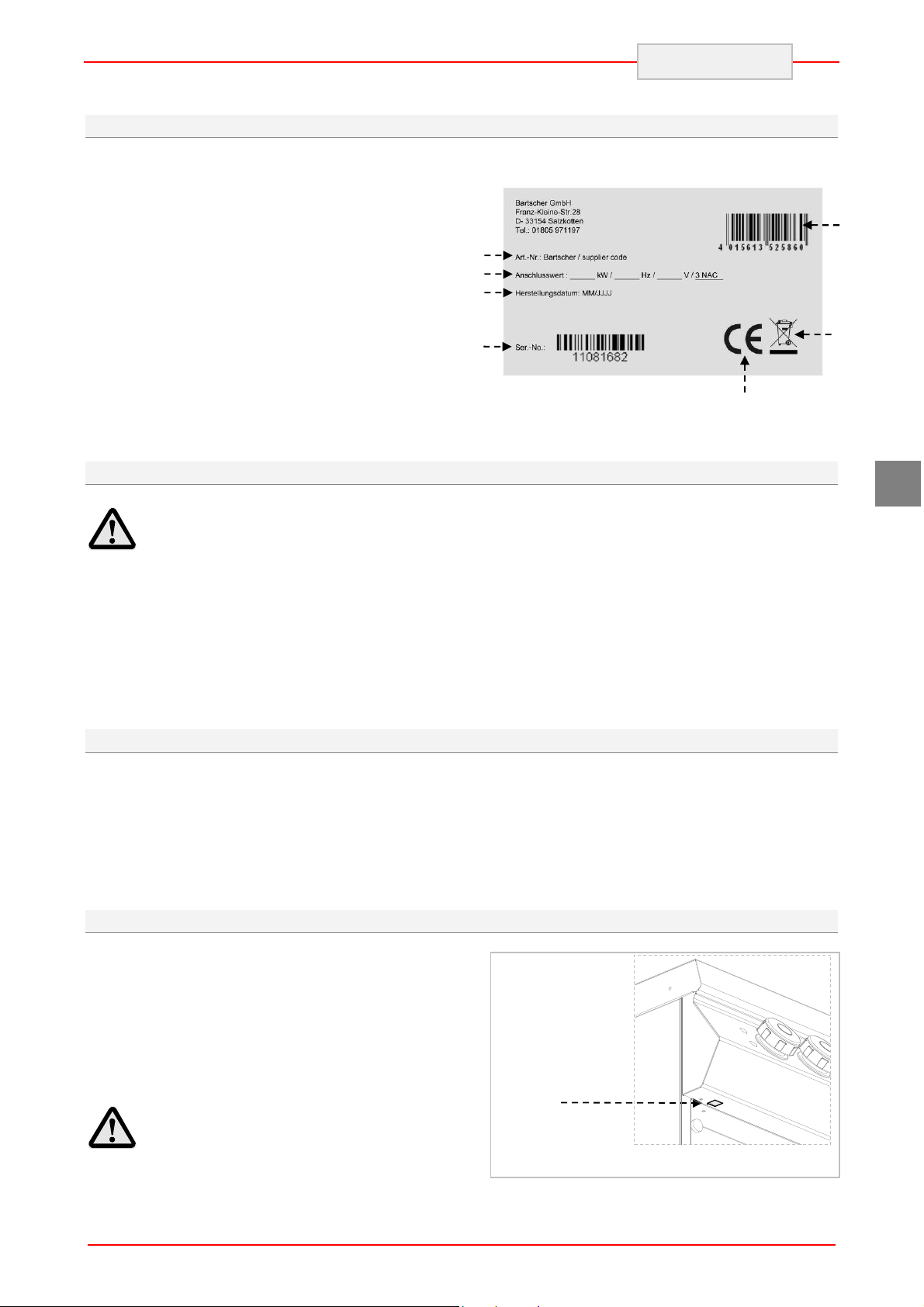
4.3. Index plate
The index plate indicated in the drawing is
mounted directly onto the device. There are all
guidelines and information on the plate required
for safe use.
1) EAN-No.
2) Code-No. / Model-No.
3) Connection: power / supply frequence /
supply voltage
4) Date of production
5) Serial-No.
6) WEEE symbol
7) CE-marking
2
3
4
4.4. Exchange of components (service technician)
ENGLISH
1
6
7
GB
Before exchange of the
component switch on all the
existing protection devices.
In particular, switch off the electric
supply with the electrical potential switch.
If necessary, exchange the used components
to the original spare parts.
4.5. Elements and accessories
The device is delivered with the following
equipment:
A. Dip tray
B. Plug
4.6. Protection devices
The device is equipped with the following
protection system:
1. Safety thermostat: Safety thermostat: it
blocks the electric power supply in the case of
over-heating.
When the safety thermostat is on it is indicated by
the red control light.
The drawing shows the safety thermostats layout.
We are not liable for personal injury or
damage to the components that arise due to
application of other spare parts than original
or intervention into the device without the
manufacturer’s consent that may have altered
the safety requirements.
On demand we can provide the following
accessories:
A. Paddle for cleaning grill plate
B. Set of blades for grooved plates
C. Construction set for right and/or left door
Check every day that the
protection devices are mounted
correctly and operational.
5
B
ENGLISH
5. USE AND OPERATION
5.1. Description of the controls.
The elements controlling the essential functions
are located on the control panel of the device.
A) Temperature control: to switch on
and off the heating elements.
B) Green indicator light: indicates
activated power supply
C) White indicator light: indicates device
heating.
D) Red indicator light: indicates activation
of safety thermostats.
GB
A
Pos. OFF
Temperature control
5.2. Device switching on and off
SWITCHING ON:
The first time the device is switched on, the
protective grease layer and any possible dirt
should be washed out from the plate. Heat it up to
200 °C.
A) Start the automatic switch-off to turn on
the electrical connection.
SWITCHING OFF
A) To switch off the electric heating elements
set the temperature control knob (A) to 0.
The green control light (B) will go off.
indicator lights
B
C
D
B) Set the temperature control knob (A) to
the desired position. The green
indicator light (B) will turn on. White
indicator light C, which indicates
heating, will turn on. When the grill
plate reaches the desired temperature,
white indicator light (C) will turn off.
B) Start the automatic switch-off to turn off
the electrical connection.
A
A
A
C
D
6

5.3. Guidelines on how to use the device
Longer interval in the use of the device
When you plan not to use the device for the
prolonged time, follow the instructions below:
1. Turn on the automatic switch-off to disconnect
from the mains;
2. Thoroughly clean the device and surrounding
areas;
3. Apply the vaseline oil on the stainless steel
surfaces;
4. Perform all maintenance works.
ENGLISH
Guidelines on regular use of the device
To ensure correct use of the device follow the
guidelines below:
Use only accessories provided by the
manufacturer;
Do not use the device for heating pots
or pans, because this may cause damage to
the grill plate.
Be especially careful when
frying foods. When frying in oil,
temperature should not exceed 190 °C.
Be especially careful not to scratch the
grill plate when removing the left over food.
GB
6. CLEANING AND MAINTENANCE
6.1. Guidelines on cleaning and maintenance
In particular, disconnect the electric
Before you start maintenance
works, turn on all the mounted
protective devices.
6.2. Correct maintenance
Proper maintenance includes daily cleaning of all
components which have contact with food
products, and regular maintenance of drain pipes.
Careful maintenance ensures the best
performance, longer life of the deviceand proper
operation of the protective devices.
Never direct the water stream or high pressure jet
towards the device.
To clean the stainless steel, do not use iron wool
or iron brush as they may leave iron particles on
the surface that form rust in result of oxidation.
In the case of prolonged intervals in the use of the
device, apply the vaseline oil onto all the stainless
steel surfaces.
power supply by means of the
automatic switch-off.
that contain substances hazardous or
harmful to health (solvents, petrol.
etc.).
At the end of the working day clean:
grill plate
device.
Regularly instruct the specialist personnel to
perform the following maintenance works:
check the electric installation;
check the safety thermostats.
Do not use any clearing agents
7

THIS
CAUTION
ENGLISH
6.3. Cleaning of the grill plate
Follow the instructions below.
1. Remove the left over food from the grill plate
with a paddle (be especially careful when
cleaning chrome plates).
2. Grease the plate with fat soluble agent and
wait a few minutes.
3. Close the drain hole with a suitable plug.
4. Pour hot water on the grill plate and wait a few
minutes.
5. Remove the dip tray.
7. PROBLEMS DURING OPERATION
6. Put a bucket under the drain hole.
7. Pull out the plug and wait until the water has
drained out.
8. Clean and dry the grill plate and the dip tray
thoroughly.
9. We recommend washing the accessories in
the dishwasher.
In order to protect the grill plate from
rust dry it thoroughly and cover it with a
protective layer of cooking oil.
GB
The information below is provided to recognize
and repair any failures that may occur when
operating the device.
Problem Cause Solution
The electrical connection is not
correct.
The heating elements
do not heat up.
Safety thermostats are on.
Damaged temperature
controller.
8. INSTALLATION
8.1. Packaging and unpacking
During unloading and when installing the
devicefollow the information from the
manufacturer placed directly on the packaging
and in this manual.
To lift and transport the product plan to use a fork
lift or stacker, and pay attention to even weight
distribution to avoid a risk of tilting of the
packaging (avoid excessive incline!).
Some of the failures can be repaired by the user,
others require thorough specialist knowledge.
Such problems may be solved exclusively by the
qualified personnel.
Check the electrical connection.
Reset the device (see special
section).
Replace temperature controller.
Contact the service company.
The packaging consists of the carton packaging
and wooden pallet. There are symbols printed on
the carton packaging that according to the
international agreements inform about the
regulations to follow when loading and unloading,
transporting and storing the device.
When using the lifting equipment
pay attention to the mains cable and
feet position.
8
SIDE UP
KEEP DRY
GLASS
ENGLISH
When collecting the goods check if the packaging
is complete and has not been damaged during
transport.
Any damage should be immediately reported to
the shipping company.
Unpack the device as soon as possible to check if
the device is not damaged.
Do not use a sharp object to cut the carton box. It
may damage the stainless steel inside the box.
Remove the carton packaging from bottom to top.
When unpacked check if the device is according
to the order.
8.2. Installation (service technician)
All the stages of the installation must be carefully
planned.
The location should be equipped with all supply
connections and production waste outlet. The
location should also be properly lit and comply
with all hygiene and sanitary requirements
according to the binding regulations.
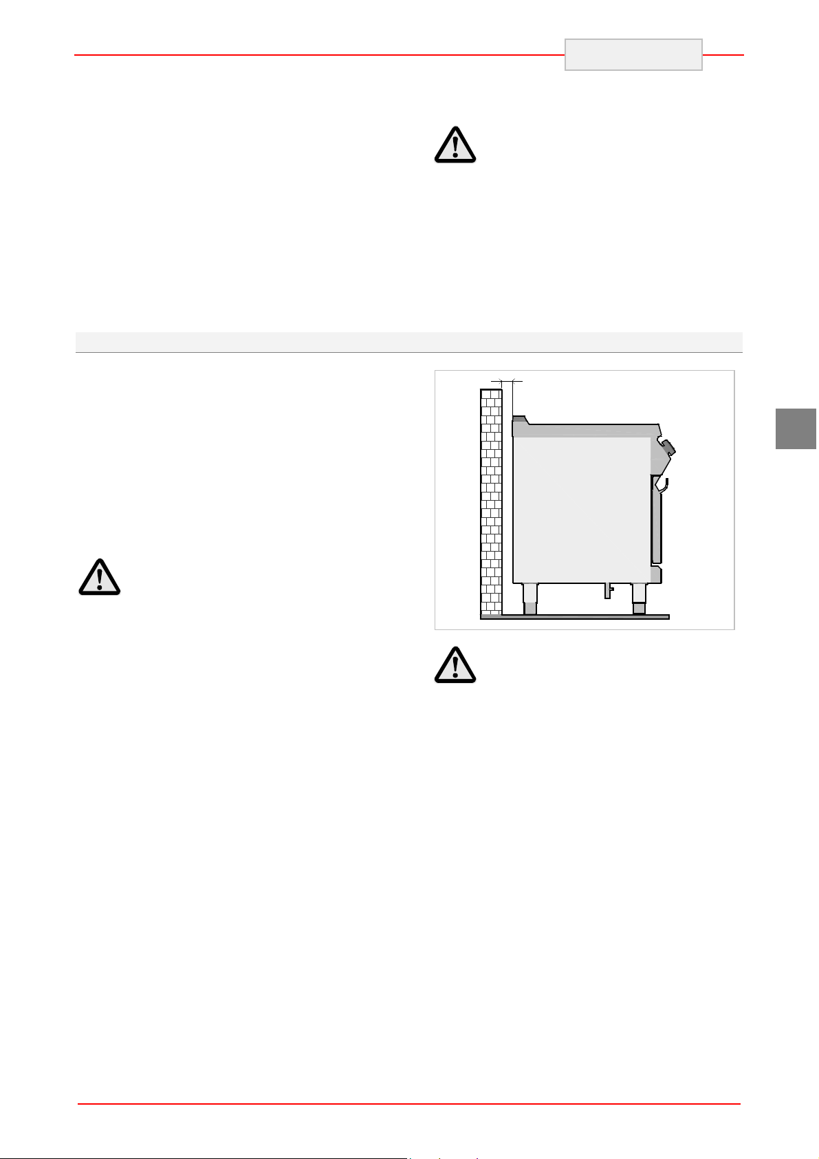
The device should be installed with the minimum
10 cm clearance from the wall.
Locate the device in the horizontal position by
adjusting the individual feet.
In case of any difference inform the sales agent
immediately.
Do not store the packaging
materials (nylon bags, polystyrene
foam, clips ...) in the reach of children!
Remove the protective PVC layer from the out
and inner surfaces. If possible, do not use any
metal tools.
10 cm
GB
When the device is to be
installed near the walls, partitions,
kitchen cabinets, decorative elements,
etc., they must be made from nonflammable materials or covered with
suitable non-flammable materials.
To ensure the correct operation
of the device, the device must be
installed and operated in the
thoroughly ventilated room only.
9

GB
A
B
C
ENGLISH
8.3. Connection to the mains (service technician)
The device may be connected to the power supply
only by the authorized and qualified personnel,
when the valid regulations are followed and when
appropriate material is used in accordance to the
regulations.
Depending on the model the devices are designed
for connection to the following networks:
400 V 3N~ 50-60 Hz
During the installation follow the data on the rating
plate.
Before connecting the device to
Connect the switch-off to the terminal strip (B)
of the device, as shown in the drawing and
block diagram (see the attachments). Use
cable type H07RN-F or better, min. heat
resistance of 80 °C.
Firmly press the end of the cable (C).
Replace the terminal strip cover.
the mains, check whether the device is
connected to the appropriate circuit
breaker in all poles with minimum air
gap of 3 mm.
To correctly connect the device, follow the
guidelines below.
Remove the cover from the terminal strip (A).
10

A
A
B
C
C
8.4. Installation of the device in a line
Um die Geräte in Reihe (Seite an Seite) zu
montieren, gehen Sie wie angegeben vor.
1. Montieren Sie die Bedientafeln ab und
entfernen Sie den Gussrahmen vom Kamin.
2. Verwenden Sie auf den aneinander
stoßenden Seitenteilen Dichtband (A)
8.5. Check-up (service technician)
Before starting the device the installation checkup should be run to evaluate the working
conditions of every single component and
recognize any errors.
ENGLISH
3. Schieben Sie die Geräte nebeneinander und
richten Sie sie horizontal aus (durch Einstellen
der Standfüße).
4. Verbinden Sie die Geräte mit den
Befestigungselementen.
It is recommended to run the following check-ups:
1. Check that the energy supply voltage is the
same as of the device voltage.
2. Turn on the automatic switch-off to check the
electrical connections.
3. Check that the protection devices work
correctly
GB
9. SETTINGS
There are no special default settings of the
device.
The only settings are those set up by the user
while using the device.
11

ENGLISH
10. DEVICE DISPOSAL
The device is marked in conformity
with the European Directive 2002/96/EG
WASTE ELECTRICAL AND ELECTRONIC
EQUIPMENT (WEEE).
By disposing the device in
accordance with the regulations the
user contributes towards prevention of
adverse effects on environment and
health.
Local waste management regulations should be
observed.
Further information on procedure, reusing and
recycling of the product is available in local
offices, waste management unit or with the
product sales agent.
GB
The symbol on the product or
attached manual indicates that the product cannot
be considered as ordinary household waste and
should be transferred to a special collection point
for electrical and electronic devices for recycling.
Bartscher GmbH
Franz-Kleine-Str. 28
D-33154 Salzkotten phone: +49 (0) 5258 971-0
Germany fax: +49 (0) 5258 971-120
12

ANLAGEN
ATTACHMENTS
ANNEXES
ALLEGATI
ANEXOS
ANEXOS
BIJLAGEN
ZAŁĄCZNIKI
I

II

ANSCHLUSSSCHEMA - CONNECTION CARD - FICHE DES RACCORDEMENTS -
BRE92MB0
SCHEDA ALLACCIAMENTI - FICHA DE ENLACES - ESQUEMA DAS CONEXÕES PLAN AANSLUITINGEN - SCHEMAT PODŁĄCZENIA
Elektroanschluss
Electric Connection
Branchement Electrique
Allacciamento Elettrico
Conexiòn elètrica
Ligação Elétrica
Elektrische aansluiting
Przyłącze elektryczne
Modell
Model
Modèle
Modello
Modelo
Modelo
Model
Model
BRE92MB0
Leistung Daten zu Elektrik
Puissance Données électrique
Potenza Dati electrici
Potencia Datos eléctricos
Potência Dados Elétricos
Vermogen
Power Electrical connection
Gegevens van de elektrische
installatie
Moc Dane dot. instalacji elektrycznej
kW V Hz
10 400V 3N~ 50/60
III
400V 3+N~
REVISION 00
50…60Hz
62887
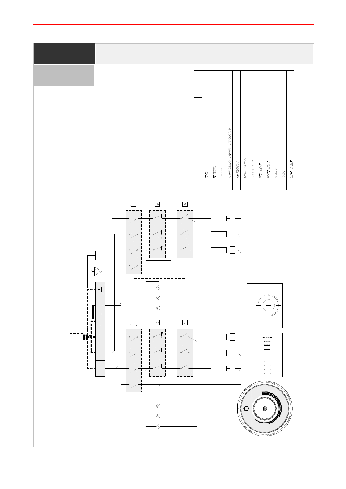
SCHALTPLAN - ELECTRIC DIAGRAM – SCHÉMA ÈLECTRIQUE - SCHEMA
ELETTRICO - ESQUEMA ELÉCTRICO - ELEKTRISCH SCHEMA - SCHEMAT IDEOWY
900
CAVO H05SJ-K
CAVO H05SJ-K
400V 3+N~ 50Hz
700
FV122 6 POLI - 40 A - 450 V
ALIMENTAZIONE
M = MORSETTIERA
EGO 55.34052.811
EGO 49.41015.300
EGO 55.32574.110
4 Poli 16A 250V T150
T=360°C -25K 20(4)A 400V
S1 = LIMITATORE DI TEMPERATURA
T1 = TERMOSTATO
B1 = COMMUTATORE
(T120) Silicon Leads
(T120) Silicon Leads
SIGNAL LUX Mod 21.3 230V
SIGNAL LUX Mod 21.3 230V
16A 250V T150 [60°C - 295°C]
MCR = MICROINTERRUTTORE
SIGNAL LUX Mod 21.3 230V
LB = LAMPADA BIANCA
LR = LAMPADA ROSSA
LV = LAMPADA VERDE
Section 1.5 mmq
230V 7.3A
(T120) Silicon Leads
1680 watt (3x)
R1,R2,R3 = RESISTENZE
Section 0.75 mmq
CABLAGGIO
CABLAGGIO LAMPADE
S1
T1
B1
P4P3P2P1
4321
24
11 21 31
12 22 32
22
11 21 31
12 32
R3R2R1
PE
75°C ±10°C
LB LR LV
B1
S1
400V 3+N~ PE 50...60Hz
P4P3P2P1
4321
24
L1 L2 L3 N N
11 21 31
12 22 32
T1
T1
295°C ±8°C
55.34052.811
R3R2R1
4 3 2 1
P4 P3 P2 P1
22
11 21 31
12 32
B1
49.41015.300
M1 M1 M1 M1 M1 M1
0 35°-318°
4 3 2 1
P4 P3 P2 P1
M
MAX
2
6
0
2
3
LV
LB LR
0
7
0
200
1
7
0
1
4
0
100
IV

NOTE
V

DE
LAUT GESETZLICHER VORSCHRIFT STEHT DIESES HANDBUCH UNTER EIGENTUMSVORBEHALT UND DARF AUS DIESEM GRUND NICHT OHNE UNSERE GENEHMIGUNG
VERVIELFÄLTIGT UND/ODER IN JEGLICHER FORM AN DRITTE WEITERGEGEBEN WERDEN!
GB
IN COMPLIANCE WITH THE LAW IN FORCE,IT IS PROHIBITED TO REPRODUCE AND/OR
DISTRIBUTE THIS MANUAL IN ANY WAY WITHOUT THE AUTHORISATION OF THE PROPRIETOR!
FR
AUX TERMES DE LA LOI, LA PROPRIETE DE CETTE NOTICE EST RESERVEE. IL EST DONC
INTERDIT DE LA REPRODUIRE ET/OU DE LA DISTRIBUER SOUS QUELQUE FORME QUE CE SOIT
SANS NOTRE AUTORISATION!
IT
A TERMINI DI LEGGE È RISERVATA LA PROPRIETÀ DI QUESTO MANUALE CON DIVIETO DI
RIPRODURLO E/O DISTRIBUIRLO IN QUALSIASI FORMA SENZA NOSTRA AUTORIZZAZIONE!
ES
DE ACUERDO CON LOS TÉRMINOS DE LA LEY ESTÁ RESERVADA LA PROPIEDAD DE ESTE
MANUAL CON EXPRESA PROHIBICIÓN DE REPRODUCIRLO Y /O DISTRIBUIRLO EN CUALQUIER
FORMA SIN NUESTRA AUTORIZACIÓN!
PT
A PROPRIEDADE DESTE MANUAL É RESERVADA POR LEI, SENDO PROIBIDA A SUA
REPRODUÇÃO E/OU DISTRIBUIÇÃO EM QUALQUER FORMA SEM A NOSSA AUTORIZAÇÃO!
NL
DE FABRIKANT BEHOUDT ZICH HET RECHT VOOR OM DE KENMERKEN VAN DE
TOESTELLEN DIE IN DEZE PUBLICATIE WORDEN VOORGESTELD TE WIJZIGEN ZONDER
VOORAF TE VERWITTIGEN!
PL
ZGODNIE Z PRZEPISAMI PRAWNYMI NINIEJSZA INSTRUKCJA JEST NASZĄ WŁASNOŚCIĄ
I Z TEGO POWODU NIE MOŻE BYĆ BEZ NASZEJ ZGODY POWIELANA I / LUB PRZEKAZYWANA
W JAKEJKOLWIEK FORMIE OSOBOM TRZECIM!
 Loading...