

Page 1
INSTRUCTION MANUAL
FOR INSTALLATION,
MAINTENANCE
AND USE
ELECTRIC TILTING COOKER
“SERIE 900”
296676
296606
12.15.01 – EN
Instruction manual for installation, maintenance and use
Electric tilging cooker Serie 900
12.15.01 - EN
23
Page 2
INDEX
1.2.
Technical data
26
1.4.
Laws, technical prescriptions and directives
27
2.1.
Positioning
28
2.2.
Installation
28
2.2.1.
Electrical connections and equipotential bonding
28
2.2.2.
Connection to waterworks
29
2.3.
Commissioning and testing
29
2.4.
Maintenance of the appliance
29
3.1.
Warnings and hints for user
31
3.2.1.
Switch on, start of cooking and switch off
31
3.3.1.
Daily cleaning
32
3.5.
Special procedures in case of failures
32
4.1.1.
Size of appliance and position of connections Mod.
58
4.2.1.
Wiring diagram Mod. BRE92MF0/BRE92MD0 230V 3/PE AC
60
4.2.3.
Wiring diagram Mod. BRE93MF0/BRE93MD0 230V 3/PE AC
62
4.3.
Knob for water inlet
64
Part 1: General reminders and notes
1.1. General reminders 25
1.3. Construction 27
1.5. Special requirements for the installation site 27
Part 2: Positioning, installation and maintenance
2.4.1.
Possible failures and their elimination
30
Part 3: Use and cleaning
3.2. Instructions for use 31
3.3. Cleaning and care of the appliance 32
3.4. Special procedures in case of long inactivity 32
3.6. How to proceed, if … 33
Part 4: Figures and detail
4.1. Size of appliance and position of connections Mod. BRE92MF0/BRE92MD0 57
BRE93MF0/BRE93MD0
4.2. Wiring diagram Mod. BRE92MF0/BRE92MD0 400V 3/N/PE AC 59
4.2.2.
Wiring diagram Mod. BRE93MF0/BRE93MD0 400V 3/N/PE AC 61
4.2.4.
4.4. Control knob 65
Instruction manual for installation, maintenance and use
Wiring diagram Motor-version 63
Electric tilging cooker Serie 900
12.15.01 - EN
24
Page 3
1.1. GENERAL REMINDER
Read the warnings contained in this manual carefully as they provide important information concerning
The appliance should be used only for the purpose for which it has been specifically designed; other
e technical
In the event of technical assistance being required, the trouble must be described in as much detail as
−
safety during the installation, use and maintenance of the appliance.
− Keep these instructions carefully!
− Only personnel trained for its specific use should use the equipment.
− Keep the appliance under control during use.
−
uses are improper and hence dangerous.
− During operation surfaces can become hot and require special operation.
− Unplug the appliance in case of failures or improper operation.
− Apply exclusively to a service centre for repairs or maintenance.
−
All important information about the appliance required for technical service is contained in th
data plate (see figure 1).
−
possible, so that a service technician will be able to understand the nature of the problem.
− Gloves should be worn to protect the hands during installation and maintenance operations.
Warning! : Follow the fire prevention regulations very carefully.
WARNING! : NOT USED ABSOLUTLY AS FRYING MODE.
S
Instruction manual for installation, maintenance and use
Brasiere elettriche Serie 900 ILSA
12.15.01 - EN
25
Page 4
T
ABLA
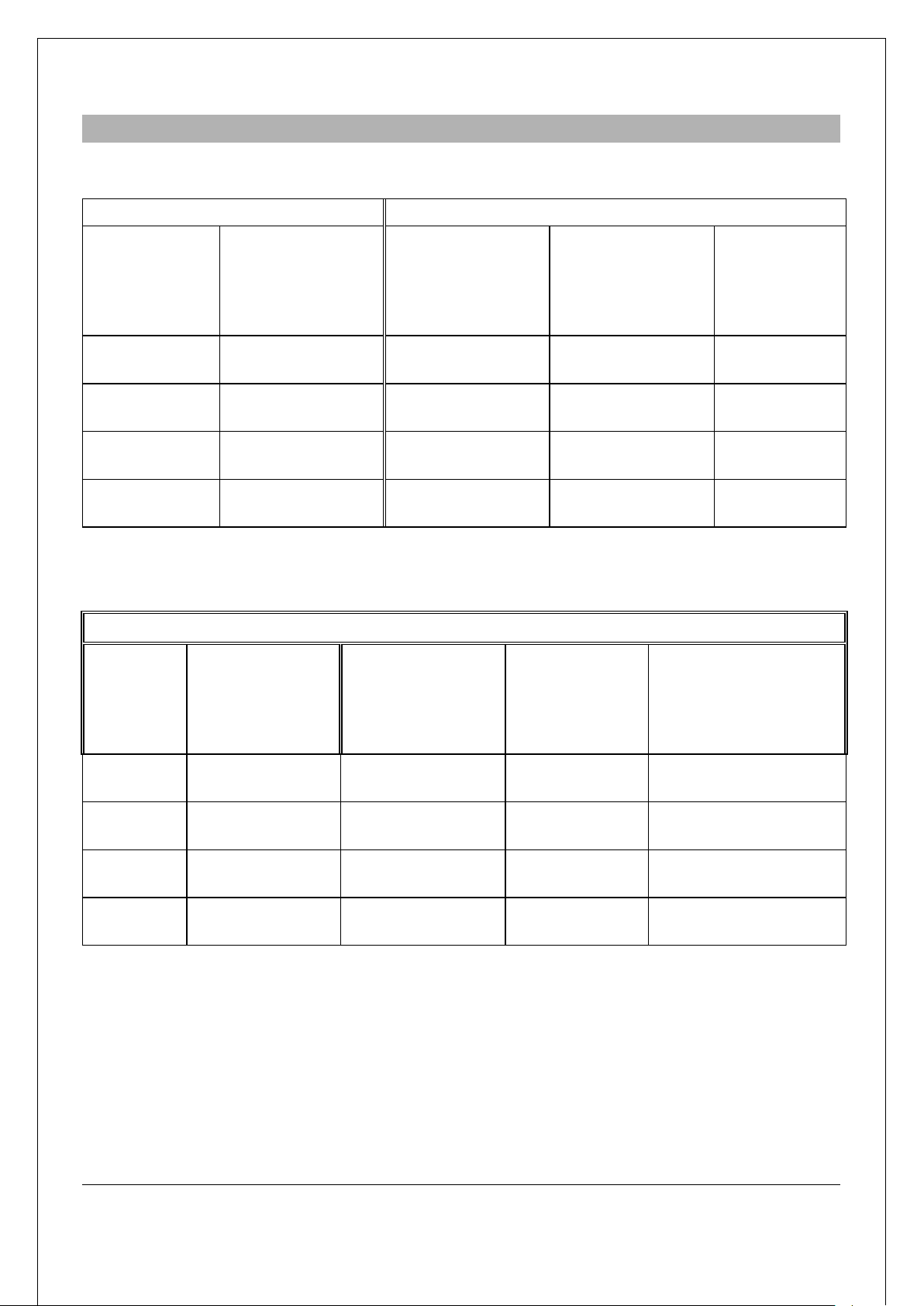
1.2. TECNICAL DATA
1
Model
External dimensions
cm
Electrics
Electric cable
2
mm
Total power
kW
BRE92MF0 80 x 90 x 90 3/N/PE AC 400 V * 5 X 4 9,9
BRE92MD0 80 x 90 x 90 3/N/PE AC 400 V * 5 X 4 9,9
BRE93MF0 120 x 90 x 90 3/N/PE AC 400 V * 5 X 6 14,9
BRE93MD0 120 x 90 x 90 3/N/PE AC 400 V * 5 X 6 14,9
2
• * Convertible to 3/PE AC 230V with electric cable sez. 4 x 4 mm
.
TABLA
2
Cooking pans characteristics
Model
Dimensions
Pan capacity
(max. level)
Rotation angle
of the pan
Minimum widith
of the outlet
Cm
litres
cm
BRE92MF0 72 x 56 x 22,5 80 80° 12,5
BRE92MD0 72 x 56 x 22,5 80 80° 12,5
BRE93MF0 110 x 56 x 22,5 120 80° 18,5
BRE93MD0 110 x 56 x 22,5 120 80° 18,5
Instruction manual for installation, maintenance and use
Electric tilging cooker Serie 900
12.15.01 - EN
26
Page 5
1.3. CONSTRUCTION
In addition, it is good policy to locate the appliance under an extractor hood so that cooking vapours can
Current regulations require the installation of a multiple pole switch between the appliance and the
The electrical isolating switch and the water shutoff valves must both be located near
- Robust steel structure on 4 adjustable feet. Exterior and top finish entirely made of stainless steel 18/10.
-
Stainless steel pan with steel bpttpm in model BRE92MF0/BRE93MF0.
- Stainless steel vat lid, INOX (AISI 304) in model BRE92MD0/BRE93MD0.
-
Lid in stainless steel, hinged and spring balanced in all opening positions.
- Hand tilting of the pan.
- Heating of the pan by means of three heating elements (3400W 240V each), fitted to the bottom of the
pan.
- Temperature regulation is possible between 45° and 295°C by means of a thermostat fitted to the
switch.
- A safety thermostat cuts off power supply automatically in case of failure (eg. breaking of thermostat ).
- A green signal lamp lights when the appliance is on.
- An orange signal lamp lights when one of the heating elements is on.
- Filling of the pan by means of a tap placed on the front panel.
1.4. LAWS, TECHNICAL PRESCRIPTIONS AND DIRECTIVES
− When installing the appliance it is necessary to follow and comply with the following regulations:
−
current regulations on the matter;
− any hygienic-sanitary regulations concerning cooking environments;
−
municipal and/or territorial building regulations and fire prevention prescriptions;
−
current accident prevention guidelines;
− electricity board regulations concerning safety;
− the regulations of the electrical power supply company or agency;
− any other local prescriptions.
1.5. SPECIAL REQUIREMENTS FOR THE INSTALLATION SITE
− The room in which the appliance is to operate must be well ventilated.
−
be removed rapidly and continuously.
−
electrical power supply; the switch must have a contact gap of least 3 mm on each pole.
− This appliance requires one water connection. The line must be fitted with an on-off valve.
Warning! :
to the appliance, within easy reach for the user.
Instruction manual for installation, maintenance and use
Electric tilging cooker Serie 900
12.15.01 - EN
27
Page 6
that the appliance is in perfect conditions. In case of visible
divided according to composition
There are no special instructions regarding distances from other appliances or walls, however it is
the appliance should be installed in direct contact with inflammable walls, it is advisable to fit a suitable
the adjustable feet: A significantly uneven or sloping stance can affect the operation of the appliance
Warning! : Only qualified technicians must perform the installation, maintenance and test of the
Before connecting any parts of the appliance to supplies, make sure that the latter is
equivalent the requirements stated in the technical data plate, if the appliance has
The appliance is supplied to operate according to the pow er supply indicated on the
As mentioned, the appliance must be connected to the power supply by way of a multiple pole main
rotection device, that must be proportioned to the power of the appliance (1 mA per
As this appliance is a type X equipment (delivery without power cable and plug), the cable and other
eeded to make the connection to the electrical power supply must be provided by the
and shall be resistant
amp. The individual wires are then fastened to the
corresponding terminals of the terminal board. The earth wire must be longer than the other wires, so
Lock
2.1. POSTIONING
− Remove all the packaging and check
damage, do not connect the appliance and notify the sales point immediately.
− Remove the PVC protection from the panels.
−
Dispose of packaging according to regulations. Generally material is
and should be delivered to the waste disposal service.
−
advisable to maintain a sufficient distance to allow any servicing operations to be performed. In the event
heat insulation.
− The appliance must stand level. Small differences in level can be eliminated by screwing or unscrewing
adversely.
2.2. INSTALLATION
appliance.
Warning! :
been designed for these supplies.
2.2.1. ELECTRICAL CONNECTIONS AND EQUIPOTENTIAL BONDING
Warning! :
data plate.
−
isolating switch and p
kW of rated power).
− The earthing system must be efficient.
−
hardware n
installer.
− The power cable shall be of the kind described in the paragraph “Technical data”
to oil.
− Proceed as follows to reach the power supply terminal board:
-
Disconnect the appliance using the switch placed before the appliance.
− Remove the fron panel, unloosing the two fixing screws.
− Remove the lid of the housing protecting the electrical components.
− The cable must be fed in from beneath the cl
that in the event of the cable being jerked or the clamp broken, the live wires will disconnect first.
the cord fastener.
− The appliance must incorporate an equipotential system.
Instruction manual for installation, maintenance and use
Electric tilging cooker Serie 900
12.15.01 - EN
28
Page 7

Connect the terminal on the lower right-
hand side marked with the international symbol a connector with a
earth system of the building shall be
It’s strictly forbidden using the pending electric cable connected with terminal board,
Water inlet pressure must be between 50 and 300 kPa, otherwise install a pressure regulator on the line
the appliance and the overall installation must be checked
that connections have been made in accordance with the requirements and directions indicated in this
In addition, check that once the appliance has been installed, the power cord is neither subject to stretch
then sign in
All maintenance operations shall only be performed by a technically qualified service
only. Maintenance includes also to control the components and tear of pipes, feeding pipes, electrical
components during maintenance operations to avoid the need for other
−
nominal cross section <10 mm2. All the appliances installed and the
connected like this.
overhanging from the frame, to connect definitely the machine.
ATTENTION!
Cut the tension before to make the connection and/or maintenance .
2.2.2. CONNECTION TO WATERWORKS
before the appliance.
- Install a cut-off valve for each supply on the line before the appliance.
-
Make connections according to regulations currently in force.
-
Water connections to 12mm. are fitted in the lower part on the left-hand side of the appliance.
2.3. COMMISSIONING AND TESTING
- Once all the connections have been made,
following the directions given in this manual.
− Check in particular:
− that the protective film has been removed from the external surfaces;
that the terminal board housing, removed for electrical connections, has been reinstalled.
manual;
− that all safety requirements in current standards, statutory regulations and directives have been met;
− that the water connections are leak-free;
− that the electrical connection has been performed according to standards.
nor in contact with nor surfaces.
- Now proceed to light the appliance as directed in the instructions for use.
-
While the appliance is in use, voltage should not differ from the nominal voltage more than +/- 10%.
- The test report must be completed in full and submitted to the customer who should
acceptance. With effect from this moment, the appliance is covered by the manufacturer’s warranty.
Warning! :
centre!
- To ensure correct and safe operation, the appliance must be inspected and serviced at least once a year
components etc..
2.4. MAINTENANCE OF THE APPLIANCE
- It is advisable to replace worn
maintenance calls and unexpected failures.
Instruction manual for installation, maintenance and use
Electric tilging cooker Serie 900
12.15.01 - EN
29
Page 8

It is also advisable to apply for a maintenance contract with the customer.
technically qualified service centres can perform the operations described
Before resetting the safety thermostat, it is always necessary to eliminate the problem
-
2.4.1. POSSIBLE FAILURES AND
Warning! : Only
below!
Warning! :
causing its activation!
Even a normal use of the appliance may cause operation inconveniences and failures.
The most common problems are the following:
P
AN DOES NOT REACH SET TEMPERATURE
Possible causes:
- Check connections to the switch.
- Check connection to the working thermostat.
- Check connection to electromagnetic switch.
- Heating elements are burned.
SIGNAL LAMPS DO NOT LIGHT UP
:
THEIR ELIMINATION
- Check the connection to the switch.
- Signal lamp is faulty.
THE BRATT PAN WORKS WITH DISCONNECTED THEMOSTAT
Electromagnetic switch contacts are cut off.
-
LOW EFFICIENTY OF THE PAN
Check t
-
he heating elements.
Instruction manual for installation, maintenance and use
Electric tilging cooker Serie 900
12.15.01 - EN
30
Page 9

Tilting cookers are ideal for preparing cream and custards, delicate dishes and sauces as it ensures a
regulation (from 50 to 200 °C) and the operator can follow the cooking cycle without
Some improper operating conditions may even be caused by an improper use of the appliance,
Respect the periods required for maintenance. With this is mind, customers are recommended to sign a
The tilting of the pan is made by means of an handwheel placed on the RH side of the front panel. Turning
3.1. WARNINGS AND HIN
− This manual contains all the instructions required for a proper and safe use of our appliances.
Keep the manual in a safe place for future consultation!
- This appliance is for catering use, hence they must be used only by trained kitchen staff.
-
The appliance must always be kept under control during use.
specific temperature
difficulties.
Warning! : The manufacturer shall not be held responsible for injuries or damage due to the non-
compliance with safety rules or an improper use of the appliance by the operator.
therefore it is important to train personnel properly.
- All the installation and maintenance operations must be performed by fitters who are members of
an official register.
-
service agreement.
- In case of failures concerning the appliance, all outputs (electrical power supply and water) must be cut
off instantly.
- In case of recurrent failures contact a service technician.
TS FOR USER
3.2. INSTRUCTIONS FOR USE
- Before cooking with the appliance for the first time wash the interior of the cooking vat thoroughly.
Warning! : Fill the cooking vat up to a maximum of 40 mm under the overflow border, according
to the maximum level mark, including the food to be cooked.
3.2.1. SWITCH ON
− Activate the main switch, placed before the appliance.
− Starting from position “0” turn the thermostat knob to desired temperature between 45° and 295°C: the
signal lamps will light , the green one indicates that the appliance is on and the orange one indicates that
heating elements are on; when the desired temperature is reached this signal lamp will go out.
Emptying the cooking vat:
the handwheel anti-clockwise the pan goes up, turning it anti-clockwise the pan goes down.
Instruction manual for installation, maintenance and use
Electric tilging cooker Serie 900
12.15.01 - EN
31
Page 10

o not use aggressive substances or abrasive detergents when cleaning the stainless steel
Avoid using metal pads of the steel parts as they may cause rust. For the same reason avoid contact
When cleaning the appliance never use direct jets of water to prevent infiltration of
External surfaces should be washed down using a sponge, and hot water with a suitable proprietary
dle for any length of time (e.g. holidays or seasonal closing) it must be
otected by applying a proprietary metal
ing use, turn it off immediately and close or cut off all
3.3. CLEANING AND CARE OF THE APP
- D
components.
with materials containing iron.
- Do not use sandpaper or abrasive paper for cleaning; in special cases use a powder pumice stone.
-
In case of particularly resistant dirt, it is advisable to use abrasive sponges (e.g. Scotch-Brite).
-
It is advisable to clean the appliance only once it has cooled down.
Warning! :
-
Clean the cooking vat with water and a detergent, rinse thoroughly and dry well with a soft cloth.
cleaner addend.
- Rinse always thoroughly and dry with a soft cloth.
3.3.1. DAILY CLEANING
the liquid and damage to components.
LIANCE
3.4. SPECIAL PROCEDURES IN CASE OF PROLONGED INACTIVITY
- If the appliance is to stand i
cleaned thoroughly, leaving not traces of food or dirt.
- Leave the lid open so that air can circulate inside the vat.
-
For added care after cleaning, the external surfaces can be pr
polish.
- Be absolutely certain to shut off all utilities (electrical power supply and water).
-
Air the room appropriately.
3.5. SPECIAL PROCEDURES IN CASE OF FAILURES
- If the appliance should not work properly dur
supplies (electrical power supply and water).
- Apply to a service centre for help.
The manufacturer shall not be held responsible nor has any warranty commitments
for damage caused by non-compliance with prescriptions or by installation not in
conformity with instructions.
The same applies in case of improper use or different application by the operator.
Instruction manual for installation, maintenance and use
Electric tilging cooker Serie 900
12.15.01 - EN
32
Page 11

3.6. HOW TO PROCEED, IF
Maintenance operations and repairs must be performed only by specialists!
Disconnect the appliance. After having removed the control knob, remove the control panel, the handle of
water inlet tap and the handwheel for tilting of pan.
R
EPLACEMENT OF HEATING ELEMENTS
- Disconnect the electric cables to heating elements.
- Remove the front fixed panel and the steady pin of the tilting pan lever..
-
Rotate the pan in the max. opening.
-
Remove the insulation protection , unloosing the fixing screws to the pan.
- Remove the protection panel of heating elements.
- Remove the heating element support plate from damaged heating element.
-
Fit the new heating element operating in the opposite order.
REPLACEMENT OF SIGNAL LAMP
- Disconnect the power cables.
…
- Remove the signal lamp, unscrewing the fixed to the control pane .
-
Fit the new signal lamp in the reverse order of operation.
REPLACEMENT OF WORKING OR SAFETY THERMOSTAT
- Disconnect power cables, after having removed the front panel.
- Remove the insulation protection, unloosing the fixing screws to the pan.
-
Remove the protection panel of heating elements.
-
Remove the support plate of central heating element.
- Remove the central heating element and then the fixing bulb boss.
- Replacing the new thermostat be careful about tightening of the boss on the bulbs.
If the bulbs would be squeezed, this would cause the damage of thermostat.
EPLACEMENT OF THE SWITCH
R
- Disconnect the power cables, after having removed the front panel.
- Replace the switch uloosing the fixing screws to the support , after having taken off the coaxial working
thermostat.
- Fit the new switch in the reverse order of operation.
Instruction manual for installation, maintenance and use
Electric tilging cooker Serie 900
12.15.01 - EN
33
Page 12

Netzanschlußklemme - Conexion electrico
Empalme agua 12 mm
4.1. DIMENSIONI E POSIZIONE DEGLI ALLACCIAMENTI
DIMENSIONS DE L’APPAREIL ET POSITIONS DES ARRIVEES
SIZE OF APPLIANCE AND
ABMESSUNGEN DES GERÄ
DIMENSIONES DEL APARATO Y UBICACIÓN DE LAS CONEXIONES
LEGENDA – LEGENDE – LEGEND - LEYENDA:
E - Allacciamento elettrico – Raccordement
électrique – Electrical connection –
TS UND ANORDNUNG DER VERSORGUNGEN
MOD. BRE92MF0/BRE92MD0
POSITION OF CONNECTIONS
A - Attacco acqua 12 mm – Raccord eau 12 mm –
Water connection 12 mm – Wasseranschluß 12 mm -
57
12.15.01
Page 13

Netzanschlußklemme - Conexion electrico
Empalme agua 12 mm
4.1.1. DIMENSIONI E POSIZIONE DEGLI ALLACCIAMENTI
DIMENSIONS DE L’APPAREIL ET POSITIO
SIZE OF APPLIANCE AND
ABMESSUNGEN DES GERÄTS UND ANORDNUNG DER VERSORGUNGEN
DIMENSIONES DEL APARATO Y UBICACIÓN DE LAS CONEXIONES
MOD. BRE93MF0/BRE93MD0
LEGENDA – LEGENDE – LEGEND - LEYENDA:
E - Allacciamenti elettrico – Raccordement
électrique – Electrical connection –
NS DES ARRIVEES
POSITION OF CONNECTIONS
A - Attacco acqua 12 mm – Raccord eau 12 mm –
Water connection 12 mm – Wasseranschluß 12 mm -
12.15.01
58
Page 14

MA Morsettiera di arrivo linea – Bornier arrivée ligne –
llegada de línea
TL Termostato di lavoro – Thermostat de travail –
funcionamiento
SE Interruttore generale – Interrupteur général –
TS Termostato di sicurezza – Thermostat de sécurité –
seguridad
C1 Teleruttore – Télérupteur – Electromagnetic switch
– Fernschalter - Telerruptor
R1 Resistenza – Résistance – Heating element –
Heizelement - Resistencia
L1 Lampada spia verde – Témoin lumineux vert –
Green signal lamp – Grüne Signallampe - Luz testigo verde
M1 Microinterruttore – Microinterrupteur – Microswitch –
Mikroschalter - Microinterruptor
L2 Lampada spia arancione – Témoin lumineux
testigo anaranjada
F3 Fusibile – Fusible – Fuse – Schmelzsicherung F4 Fusibile – Fusible – Fuse – Schmelzsicherung -
Fusibile 25 A
3/N/PE AC 400 V
F4
mA
F3
N
L2 L1 L3
TS
R1
C1
3
1
5
SE
A1
4
2
6
A2
R1
P4
P2
1
P1
3
P3
2
4
M1
L1 L2
TL
SCHEMA ELETTRICO – SCHEMA ELECTRIQUE – WIRING DIAGRAM –
4.2.
ELEKTRISCHER SHALTPLAN - ESQU
MOD. BRE92MF0/BR
400V 3/N/PE AC
LEGENDA – LEGENDE – LEGEND - LEYENDA:
Junction block – Anschlußklemme - Tabl. de bornes de
General switch – Hauptschalter - Interruptor general
orange – Orange signal lamp – Orange Signallampe - Luz
EMA ELÉCTRICO
E92MD0
Thermostat – Betriebstemperaturregler - Termostato de
Safety thermostat – Temperaturbegrenzer - Termostato de
Fusibile 3,15 A
12.15.01
59
Page 15

MA Morsettiera di arrivo linea – Bornier arrivée
de
línea
TL Termostato di lavoro – Thermostat de travail –
SE Interruttore generale – Interrupteur général –
TS Termostato di sicurezza – Thermostat de
seguridad
C1 Teleruttore – Télérupteur – Electromagnetic
switch - Telerruptor
R1 Resistenza – Résistance – Heating element Resistencia
L1 Lampada spia verde – Témoin lumineux vert
– Green signal lamp - Luz testigo verde
M1 Microinterruttore – Microinterrupteur –
Microswitch - Microinterruptor
L2 Lampada spia arancione – Témoin lumineux
anaranjada
F3 Fusibile – Fusible – Fuse - Fusibile 3,15 A
F4 Fusibile – Fusible – Fuse - Fusibile 25 A
2
F4
L1
mA
F3
TS
1
230 V - 3/PE AC
L2 L3
C1
3 5
A1
P1
SE
1
4
6
A2
P4
3
P3
P2
2
L1
4
TL
M1
L2
R1
R1
4.2.1. SC
HEMA ELETTRICO – SCHEMA ELECTRIQUE – WIRING DIAGRAM - ESQUEMA ELÉCTRICO
MOD. BRE92MF0/BR
230V 3/PE AC
LEGENDA – LEGENDE – LEGEND - LEYENDA:
ligne – Junction block - Tabl. de bornes de llegada
General switch - Interruptor general
orange – Orange signal lamp - Luz testigo
E92MD0
Thermostat -Termostato de funcionamiento
sécurité – Safety thermostat - Termostato de
12.15.01
60
Page 16

4.2.2. SCH
MA Morsettiera di arrivo linea – Bornier arrivée
bornes de llegada de línea
TL Termostato di lavoro – Thermostat de travail –
de funcionamiento
SE Interruttore generale – Interrupteur général –
TS Termostato di sicurezza – Thermostat de
- Termostato de seguridad
C1 Teleruttore – Télérupteur – Electromagnetic
switch - Fernschalter - Telerruptor
R1 Resistenza – Résistance – Heating element –
Heizelement - Resistencia
L1 Lampada spia verde – Témoin lumineux vert
testigo verde
M1 Microinterruttore – Microinterrupteur –
L2 Lampada spia arancione – Témoin lumineux
- Luz testigo anaranjada
EMA ELETTRICO – SCHEMA ELECTRIQUE – WIRING DIAGRAM –
ELEKTRI
LEGENDA – LEGENDE – LEGEND - LEYENDA:
– Junction block – Anschlußklemme - Tabl. de
ligne
General switch – Hauptschalter - Interruptor general
– Green signal lamp – Grüne Signallampe - Luz
orange – Orange signal lamp – Orange Signallampe
SCHER SCHALPLAN - ESQUEMA ELÉCTRICO
MOD. BRE93MF0/BRE93MD0
400V 3/N/PE AC
Thermostat – Betr
sécurité – Safety thermostat – Temperaturbegrenzer
Microswitch – Mikroschalter - Microinterruptor
iebstemperaturregler - Termostato
12.15.01
61
Page 17

2.3. SCHEMA ELETTRICO – SCHEMA ELECTRIQUE –WIRING DIAGRAM –
MA M
orsettiera di arrivo linea
– Bornier arrivée
bornes de llegada de línea
TL Termostat
o di lavoro
– Thermostat de t
ravail
–
de funcionamiento
SE Interruttore generale – Interrupteur général –
TS Termostato di sicurezza – Thermostat de
Termostato de seguridad
C1 Teleruttore – Télérupteur – Electromagnetic
switch – Fernschalter - Telerruptor
R1 Resistenza – Résistance – Heating element –
Heizelement - Resistencia
L1 Lampada spia verde – Témoin lumineux vert
testigo verde
M1 Microinterruttore – Microinterrupteur –
L2 Lampada spia arancione – Témoin lumineux
-Luz testigo anaranjada
TL
SE
230 V - 3/PE AC
L1 L2 L3
P2
P1
P4
P3
C1
R1
C1
M1
2 1 4
3
TS
L2
R1
R1
L1
4.
ELEKTR
LEGENDA – LEGENDE – LEGEND - LEYENDA:
gne – Junction block –Anschlußklemme - Tabl. de
li
General switch – Hauptschalter - Interruptor general
– Green signal lamp – Grüne Signallampe - Luz
orange – Orange signal lamp – Orange Signallampe
ISCHER SHALTPLAN - ESQUEMA ELÉCTRICO
. BRE93MF0/BRE93MD0
MOD
230V 3
/PE AC
Thermostat –Bet
sécurité – Safety thermostat –Temperaturbegrenzer -
Microswitch – Mikroschalter - Microinterruptor
riebstemperaturregler - Termostato
mA
62
12.15.01
Page 18

. SCHEMA ELETTRICO VERSIONE MOTORIZZATA
MA M
orsettiera di arrivo linea
– Bornier arrivée l
igne
de llegada de línea
M2 Fi
necorsa salita
– Fi
n de course montée
–
Microinterruptor elevaciòn
F1 Fusibile generale neutro – Fusible général
Schmelzsicherung - Fusibile general neutro 3,15 A-T
RS Relè salita vasca – Relais montée cuve –
subida de la cuba 1P 30A
F2 Fusibile – Fusible – Fuse – Schmelzsicherung -
RD Relè discesa vasca – Relais descente cuve –
Pfanne - Relé bajada de la cuba 1P 30A
SE2 Selettore ribaltamento vasca – Sélecteur
Mm Motoriduttore monofase ribaltamento –
Kippung - Microinterruptor monofàsico inclinaciòn
M1 Finecorsa discesa – Fin de course descente –
Microinterruptor descenso
Co Condensatore – Condensateur – Capacitor –
TL Termostato di lavoro – Thermostat de travail –
funcionamiento
230V
N
L1
F1
S
D
NC
4.2.4
SCHEMA ELEC
LEGENDA – LEGENDE – LEGEND - LEYENDA:
Junction Block –Anschlußklemme - Tabl. de bornes
–
neutre – Fender-fuse for general-neutral –
Fusibile 16A
renversement cuve – Selector tilting of pan – Slektor Seletor vuelco cuba
Lowering limit switch – Mikroschalter Rückstellung -
Thermostat –Betriebstemperaturregler - Termostato de
TRIQUE VERSION MOTORISEE - WIRING DIAGRAM MOTOR-VERSION
LEKTRISCHER SCHALTPLAN MOTOR-VERSION
E
ESQUEMA EL
ÉCTRICO VERSION MOTORIZADO
ising limit switch – Mikroschalter Kippung -
R
Relay vat rising – Relais Kippung der Pfanne -Relé
Relay vat lowering – Relais Rückstellung der
Motoréducteur monophase renversement – Tilting
single-phase ratiomotor – Getriebemotor einphasig
Konsensator - Condensador
ONLY FOR ELECTRIC MOD
TL
SE2
NC
RD
mA
M1
Mn
M2
A1
RS
F2
F2
Co
12.15.01
63
Page 19

RUBINETTO DI CARICO DELL’ACQUA PER LA VASCA DI COTTURA
4.3.
MANETTE D’ALIMENTATIO
BEDIENNUNGSKNEBEL WASSERFÜLLUNG
BOTÓN PARA EL CARGO DE LA AGUA
N DE L’EAU – KNOB FOR WATER INLET
SENSO DI CARICO SENSO DI CHIUSURA
SENS DE CHARGEMENT SENS DE FERMETURE
WAY FOR WATER INLET STOP WATER INLET
DREHRICHTUNG FÜR WASSER FÜLLUNG SCHLIEß DREHRICHTUNG
ABIERTO CERRADO
12.15.01
64
Page 20

MANOPOLA DI COMANDO – POIGNEE DE COMMANDES -
A Manopola di comando – Poignée de commande
C Posizione di salita vasca – Position de
kippung des tiegels - Posición subida de la cuba
B Posizione di spento – Position de fermé – Off
apagado
D Posizione di discesa vasca – Position de
rückstellung des tiegels - Posición bajada de la cuba
A
B C
D
0
45
100
150
200
250
295
295
250
200
150
100
45
0
295
250
200
150
100
0
45
4.4.
CONTROL KNOB – BED
IENUNGSGRIFF - MANDOS
LEGENDA – LEGENDE – LEGEND - LEYENDA:
A. Manopola di comando – Poignée de commandes – Control knob – Bedienungsgriff - Botón de
mando
B. Posizione di spento – Position éteinte – Off position – Geschlossenstellung - Posición de
apagado
C. Posizione di minimo – Position minimum – Minimum position – Kleinstellung - Posición de
mínimo
D. Posizione di massimo – Position maximum – Mximum position – Großstellung - Posición de
máximo
RIBALTAMENTO VASCA MOTORIZZATO – RENVERSEMENT CUVE MOTORISEE – MOTOR TILTING
PAN – MOTOR KIPPVORRICHTUNG - VUELCO CUBA MOTORI ZADO
LEGENDA – LEGENDE – LEGEND - LEYENDA:
– Control knob - Bedieungsknebel - Botón de mando
position – Geschlossen-Stellung - Posición de
montée cuve – Position for vat tilting – Stellung für
descente cuve – Position for vat return – Stellung für
POSIZIONE “B” POSIZIONE “C” POSIZIONE “D”
12.15.01
65
 Loading...