

Bartscher 296411, IR092M01, IRE92M01, IR091M01, 296421 Installation, Operating And Maintenance Instructions
...Page 1
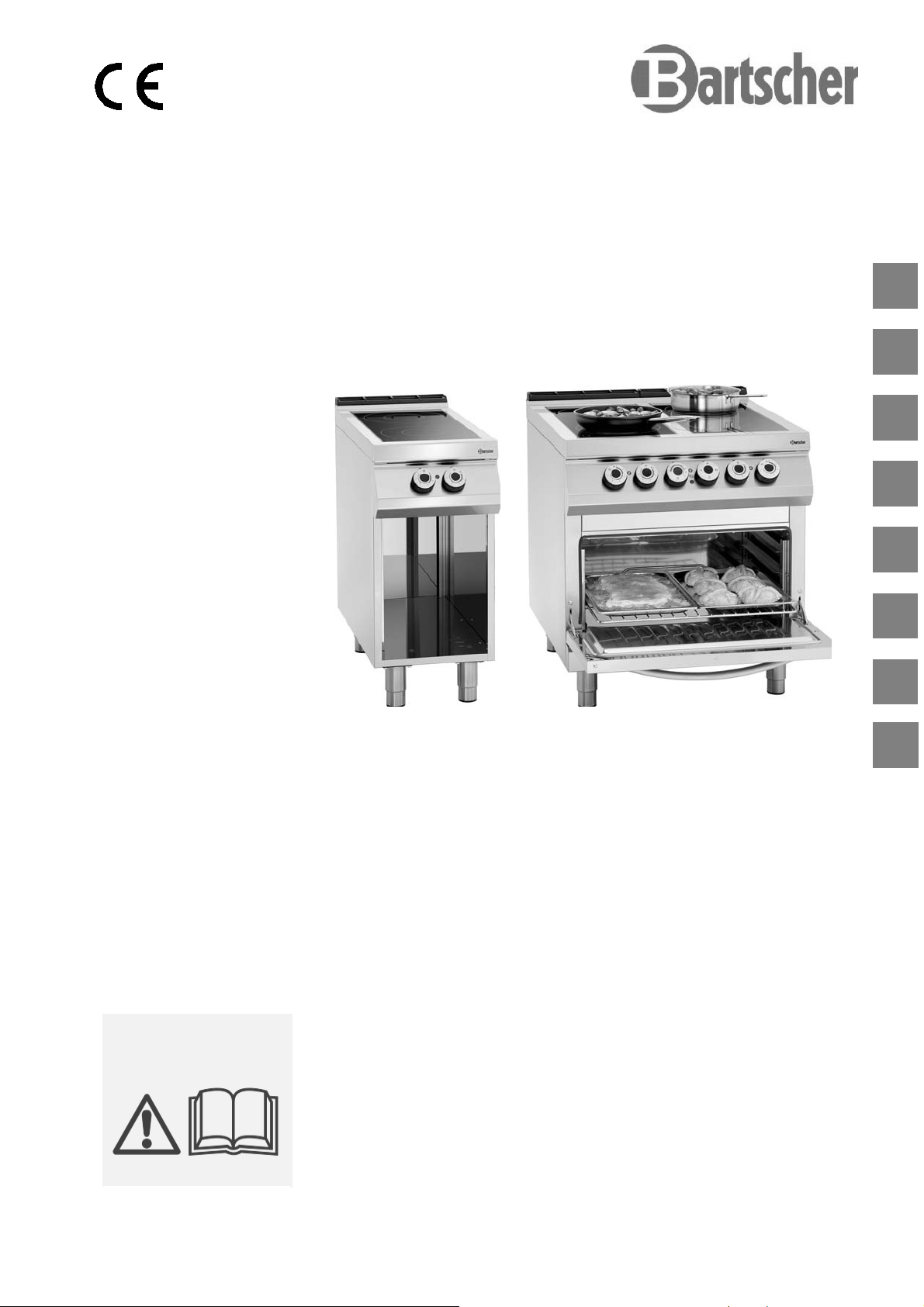
CERA N H E R D E
CERAMIC GLASS STOVE
FOURNEAU VITROCERAMIQUE
CUCINA VETROCERAMICA
COCINA DE VITROCERAMICA
296411 / IR091M01
296421 / IR092M01
296321 / IRE92M01
FOGÕES DE CERÂMICA
KERAMISCH FORNUIS
KUCHNIA CERAMICZNA
DE
GB
FR
IT
ES
PT
NL
Rev.-Nr.: 01-2017
INS T A LLA T I O N S-, B E DIE N U N GSUN D W AR T UNGS A NW E ISU N GEN
INS T A LLA T I O N , O P E R ATI N G
AND M AINT E N ANC E N STRU C T IONS
MA N U E L D' I N STAL L ATION ,
D' U T I LISA T I O N E T D 'E N T R E TIE N
MA N U A LE D I I NST A L L AZI O N E ,
US O E MA N U T E NZ I O N E
MA N U A L DE I N STA L A C IÓN,
US O Y MA N T E N IMI E N T O
MA N U A L DE I N STA L A ÇÃO,
UT I L I ZAÇÃ O E MA N U T ENÇÃ O
HA N D L EIDI N G VOOR I NST A L L ATIE ,
GE B R U IK E N O ND E R H O UD
W SK A Z ÓW KI DO T Y C ZĄ C E I NST A L A CJI,
UŻ Y T K OW AN IA I KONS E RW AC J I
PL
Page 2

DE
TECHNISCHE ÄNDERUNGEN VORBEHALTEN!
GB
FR
IT
ES
PT
NL
TECHNICAL CHANGES RESERVED!
SOUS RÉSERVE DE MODIFICATIONS TECHNIQUES !
CI RISERVIAMO LA POSSIBILITÀ DI INTRODURRE MODIFICHE TECNICHE!
¡SE RESERVA EL DERECHO A INTRODUCIR MODIFICACIONES TÉCNICAS!
SUJEITO A ALTERAÇÕES TÉCNICAS!
TECHNISCHE WIJZIGINGEN VOORBEHOUDEN!
PL
WPROWADZANIE ZMIAN TECHNICZNYCH ZASTRZEŻONE!
Page 3

ENGLISH
1. TABLE OF CONTENTS
1. TABLE OF CONTENTS ..................................................................................................................... 1
2. INDEX ................................................................................................................................................. 2
3. SAFETY .............................................................................................................................................. 3
4. GENERAL INFORMATION AND WARNINGS ................................................................................... 4
4.1. General guidelines ................................................................................................................... 4
4.2. Description of the appliance ..................................................................................................... 4
4.3. Index plate ................................................................................................................................ 5
4.4. Exchange of components (service technician) ........................................................................ 5
4.5. Protection devices .................................................................................................................... 5
5. USE AND OPERATION ..................................................................................................................... 6
5.1. Description of the use the device. ............................................................................................ 6
5.2. Heating plate switching on and off ........................................................................................... 7
5.3. Oven switching on and off ........................................................................................................ 8
5.4. Guidelines on how to use the appliance .................................................................................. 8
6. CLEANING AND MAINTENANCE ..................................................................................................... 9
6.1. Guidelines on cleaning and maintenance ................................................................................ 9
6.2. Correct maintenance ................................................................................................................ 9
6.3. Cleaning of ceramic plate ....................................................................................................... 10
6.4. Cleaning of the oven .............................................................................................................. 10
7. PROBLEMS DURING OPERATION ................................................................................................ 11
8. INSTALLATION ................................................................................................................................ 11
8.1. Packaging and unpacking ...................................................................................................... 11
8.2. Installation (service technician) .............................................................................................. 12
8.3. Installation of the appliance in a line ...................................................................................... 13
8.4. Connection to the mains (service technician) ........................................................................ 13
8.5. Check-up (service technician) ................................................................................................ 15
9. APPLIANCE DISPOSAL .................................................................................................................. 16
ATTACHMENTS ....................................................................................................................................... I
Bartscher GmbH
Franz-Kleine-Str. 28
33154 Salzkotten phone: +49 (0) 5258 971-0
Germany fax: +49 (0) 5258 971-120
GB
1
Page 4
ENGLISH
2. INDEX
GB
A
APPLIANCE DISPOSAL 16
C
Check-up 15
Cleaning of ceramic plate 10
Cleaning of the oven 10
Connection to the mains 13
Correct maintenance 9
D
Description of the appliance 4
Description of the of the use the device 6
E
Exchange of components 5
G
General guidelines 4
Guidelines on cleaning 9
Guidelines on how to use the appliance 8
Guidelines on regular use of the appliance 8
H
Heating plate switching on and off 7
Heating plates - safety thermostat 5
I
Index plate 5
Installation 12
Installation of the appliance in a line 13
L
Longer interval in the use of the appliance 8
M
Maintenance 9
O
Oven - safety thermostat 5
Oven switching on and off 8
P
Packaging 11
PROBLEMS DURING OPERATION 11
Protection devices 5
R
Residual heat indicator light. 6
S
SAFETY 3
U
Unpacking 11
2
Page 5
3. SAFETY
Read carefully the guidelines and
instructions in the instruction manual
before you use the appliance.
The instruction manual contains general
information on how to safely use and maintain the
appliance. Retain the manual for future reference.
Electric installation conforms to CEI EN
60335-1 and 60335-2-36 regulation.
To prevent any hazard, the damaged
mains power cable may be replaced by the
manufacturer or service personnel only.
The manufacturer took extra care when designing
and manufacturing to prevent any safety or health
hazard to the personnel operating the appliance.
Please read carefully the guidelines in the
instruction manual and instructions placed directly
onto the appliance. Above all, observe all the
safety instructions.
Do not intervene in or remove the protective
devices installed in the appliance. Noncompliance may lead to severe safety and health
hazard against people. We recommend to perform
a few tests to know the layout and main functions
of the control panel, particularly those to switch
the appliance on and off.
The appliance is intended only for the use it has
been designed for and any other use is
considered as the use not in compliance with the
intended use.
The manufacturer is not liable for material
damage or damage to person caused by
misapplication or incorrect application of the
appliance.
Any maintenance work that requires special
technical license or special skills may be
performed by qualified personnel only.
ENGLISH
To provide hygiene and protect foods from dirt, all
the elements that have direct or indirect contact
with the foods and all border areas must be
thoroughly cleaned. Use only the cleaning agents
intended for use in contact with food and avoid
using flammable agents or harmful to health.
After each use of the appliance make sure that all
the heating elements and control elements have
been switched off and the cable unplugged.
In case of prolonged interval in using the
appliance disconnect all power supply cables and
thoroughly clean the inside and outside elements
of the appliance.
In direct connection to the mains
the safety switch should be supplied
where wire joints dilation is large enough
to secure disconnection in category III
overvoltage, which is in accordance with
the installation rules.
The device requires some safety
measures during installation, positioning,
fixing, and connecting to the power supply
(section 8 “INSTALLATION”).
Do not clean the device with direct
stream of water.
When the cooker surface is cracked
immediately disconnect it from the power
supply.
Do not place any plastic containers on
hot surface of the cooker.
Avoid using the aluminium foil for
protecting the surfaces during the device
operation.
GB
3
Page 6
GB
ENGLISH
4. GENERAL INFORMATION AND WARNINGS
4.1. General guidelines
The manual has been edited by the manufacturer
to provide the authorized personnel with the
information necessary to work with the appliance.
We recommend the intended readers to read the
manual carefully and comply with the information.
By reading the information contained in the
manual, hazards against people health and safety
may be prevented.
Retain the manual in an easily available place
throughout the time of use of the appliance to
have access and refer to the required information
at any time.
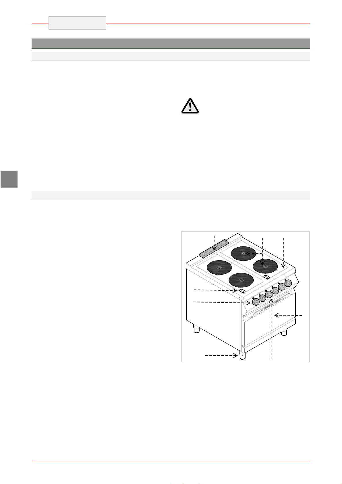
4.2. Description of the appliance
Special symbols, described below, have been
used to stress important information or draw
attention to essential data:
Warning
Indicate important safety
instructions. You should acquire the
proper conduct to prevent hazard against
people health and safety or not to cause
any damage.
Caution
Indicate essentials technical data that
you cannot ignore.
The electric cooker with infrared ceramic heating
plate has been designed and manufactured for
preparing and cooking of food products in the
professional gastronomy sector.
1) Cooker: with ceramic heating plate and
infrared heating coil;
2) Hob;
3) Temperature controller: adjusts power
of electric heating plate;
4) Feet of adjustable height;
5) Power supply indicator light: indicates
activation of supply voltage.
6) Heating plates indicator light: Indicates
activation of the heating plates and is on
when their temperature exceeds 50°C
7) Electric oven (static);
8) Oven smoke extraction;
9) Oven thermostat controller: adjusts
temperature of the electric oven
10) Oven switch: turns on or off the oven
heating coils.
11) Thermostat indicator light: indicates
activation of the safety thermostats.
12) Power supply indicator light: indicates
activation of supply voltage.
13) Temperature indicator light: indicates
oven heating.
8
6
3 5
4
2
9 10 11 12 13
1
7
4
Page 7
2
5
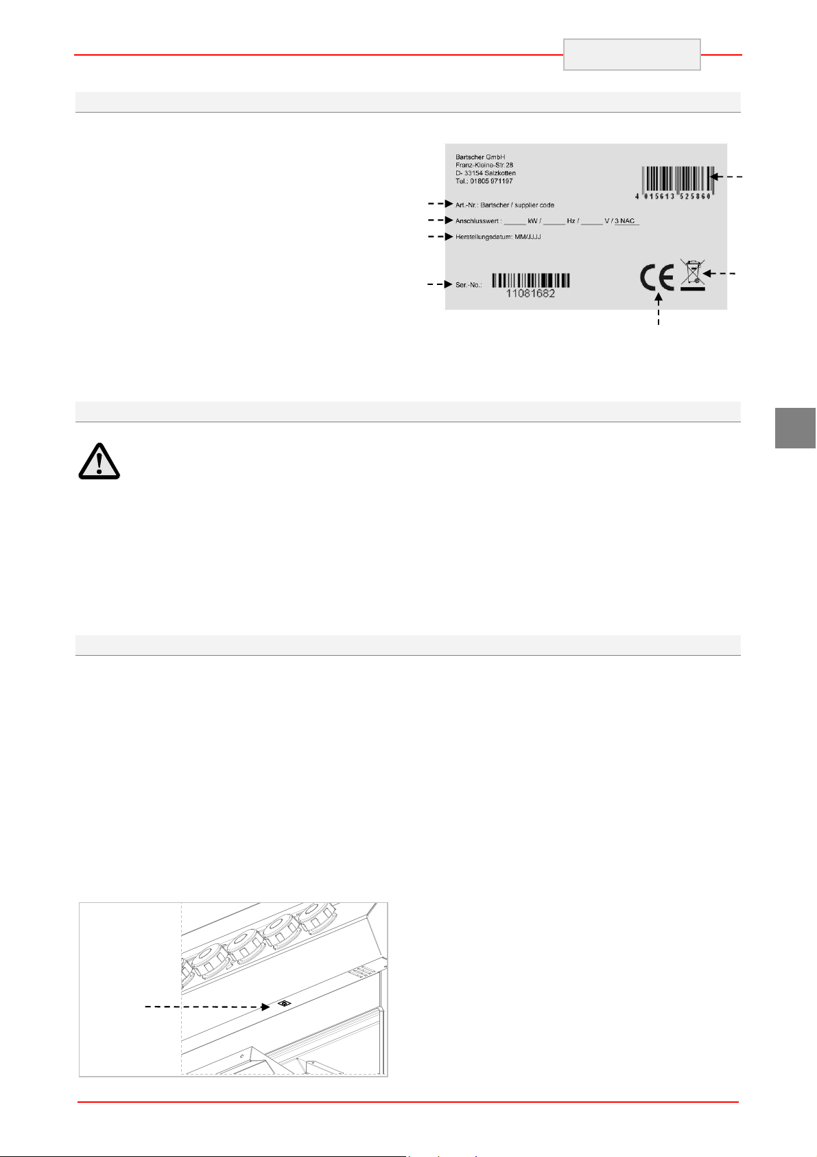
4.3. Index plate
The index plate indicated in the drawing is
mounted directly onto the appliance. There are all
guidelines and information on the plate required
for safe use.
1) EAN-No.
2) Code-No. / Model-No.
3) Connection: power / supply frequence /
supply voltage
4) Date of production
5) Serial-No.
6) WEEE symbol
7) CE-marking
2
3
4
4.4. Exchange of components (service technician)
ENGLISH
1
6
7
GB
Before exchange of the component
switch on all the existing protection
devices.
In particular, switch off the electric
supply with the electrical potential switch.
If necessary, exchange the used components
to the original spare parts.
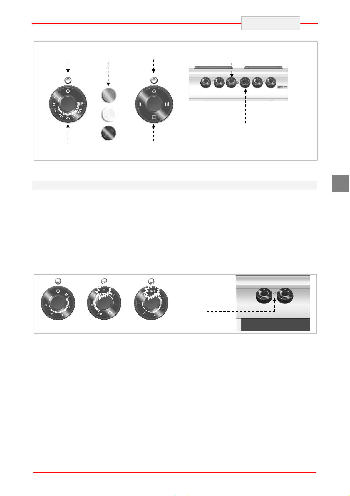
4.5. Protection devices
The device is equipped with the following
protection systems:
1. Heating plates - safety thermostat: It is the
device inside each heating plate which
reduces power in case of overheating. When
the reason is removed and temperature
drops, the operation is automatically restored.
2. Oven - safety thermostat: Cuts off the oven
power supply in case of overheating.
Safety thermostat activation is indicated by
appropriate indicator light. Figure shows position (2)
of oven safety thermostats.
We are not liable for personal injury or
damage to the components that arise due to
application of other spare parts than original
or intervention into the appliance without the
manufacturer’s consent that may have altered
the safety requirements.
5
Page 8
Front heating
Back heating
The ceramic cooker is equipped IN STANDARD
with RESIDUAL HEAT INDICATOR LIGHT on
the cooker, which indicates that temperature of
the cooking surfaces exceeds 70°C and warns the
user to NOT TO TOUCH the cooking surfaces to
avoid burns. The indicator light becomes on after
few minutes from the activation of cooker heating
coils and remains on during the normal operation.
After deactivation of the heating plates it remains
on until the temperature drops below 50°C.
ENGLISH
Keep in mind that in case of sudden
power supply failure there is the risk of
burns as the cooking surfaces may be still
hot.
Check every day that the protection
devices are mounted correctly and
operational.
GB
5. USE AND OPERATION
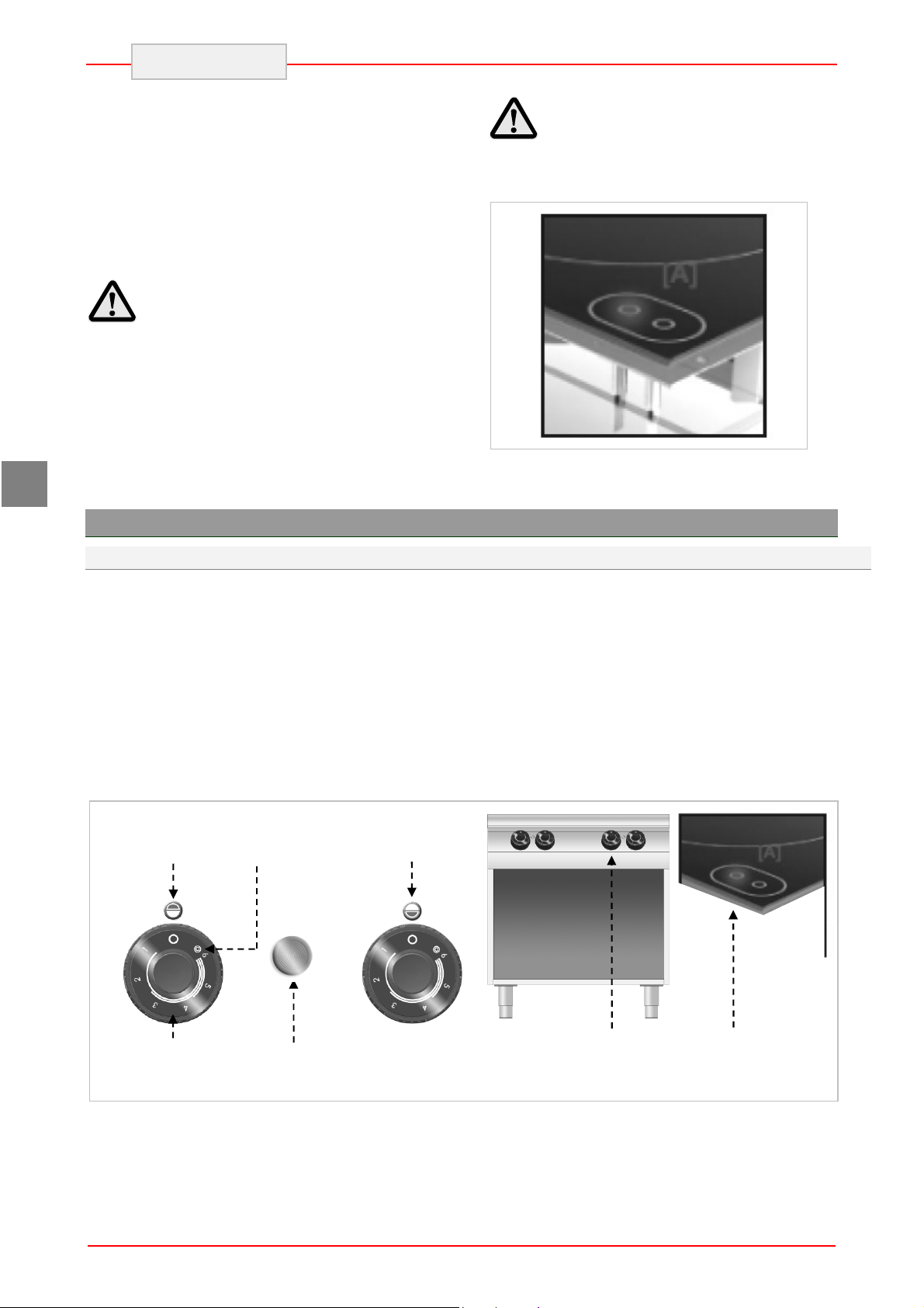
5.1. Description of the use the device.
The elements controlling the essential functions
are located on the control panel of the device.
A) Temperature controller: adjusts power
of electric heating plates
B) Oven thermostat controller: adjusts
temperature of the electric oven
C) Oven switch: activates upper, lower, or
both heating coils.
D) Green indicator light: indicates activated
power supply
Maximum
plate position
power
position
plate position
E) White indicator light: indicates oven
heating
F) Red indicator light: indicates activation of
safety thermostats.
G) Indicator light of heating plates:
indicates activation of electric heating
plates.
A
Plate power
D
Supply voltage
indicator light
6
A
G
Page 9
Oven indicator
Oven heating coils
position
position
ENGLISH
Oven
lights
Oven
D
E
B
F
Oven
temperature
5.2. Heating plate switching on and off
During the first activation leave the heating plates
for heating without pots.
A) Start the automatic switch-off to turn on
the electrical connection.
B) Turn the temperature controller to position 1
to set the heating plate to minimum power.
The green control light (V) will come on.
C) Then turn the temperature controller to
desired position.
position
C
Oven – thermostat
controller
Oven switch
GB
D) Turn the temperature controller to position
A to set the heating plate to maximum
power.
E) Turn the temperature controller to position 0
to switch off the heating plate. The green
control light (V) will go off.
F) Start the automatic switch-off to turn off
the electrical connection, when needed.
V
Pos 0
Pos A
7
Page 10

ENGLISH
5.3. Oven switching on and off
A) Start the automatic switch-off to turn on
the electrical connection.
B) Turn switch A to activate the oven heating
coils. The green control light (L) will come
on.
C) Turn the oven temperature controller and
set it between 70°C and 300°C.
When the heating coils are activated, the
white indicator light (W) will come on.
Temperature °C 70 100 130 160 200 240 270 300
Time in minutes 1’ 30” 3’ 4’ 30’ 6’ 8’ 11’ 14’ 17’
When the oven reaches required temperature the white indicator light goes off.
D) Turn switch (A) to activate or deactivate
the upper, lower, or both heating coils.
E) To switch the oven off turn the switch (A)
to position 0. Then turn the thermostat
controller (B) to position 0.
GB
A
Pos 0
Pos 1
Pos 0
B
5.4. Guidelines on how to use the appliance
Longer interval in the use of the appliance
When you plan not to use the appliance for the
prolonged time, follow the instructions below:
1. Turn on the automatic switch-off to disconnect
from the mains;
2. Thoroughly clean the appliance and
surrounding areas;
3. Apply the vaseline oil on the stainless steel
surfaces;
4. Perform all maintenance works.
Guidelines on regular use of the appliance
To ensure correct use of the device follow the
guidelines below:
Use only accessories provided by the
manufacturer;
Use the heating plates only for heating pots,
do not heat food products directly on the
plates.
The device and its vicinity should be always
kept clean.
Use containers of diameter not lower than
diameter of the heating plates.
L
Pos 1
Use only pots with flat bottom.
Cast iron steak frying pans and other metal
alloys are not suitable for use on the ceramic
cooker as high bottom thickness may cause
dangerous heat concentration on the cooker.
Besides, rough bottom may scratch the
surface and the metal alloy may leave
permanent stains.
Use only food grade cleaning agents.
8
Page 11

Check if the oven door is properly installed.
Heat the oven before use.
protecting the surfaces during the device
Do not use the oven with partially
opened door.
In order to brown the product surface
put in on the upper grill and switch the upper
coil on.
Do not use the heating plates
without pots. Switch the heating plate off
when not in use.
operation.
Before putting the pots on the cooker clean
6. CLEANING AND MAINTENANCE
6.1. Guidelines on cleaning and maintenance
In particular, disconnect the electric
Before you start maintenance
works, turn on all the mounted protective
devices.
6.2. Correct maintenance
Proper maintenance includes daily cleaning of all
components which have contact with food
products, and regular maintenance of drain pipes.
Careful maintenance ensures the best
performance, longer life of the appliance and
proper operation of the protective devices.
Never direct the water stream or high pressure jet
towards the appliance.
To clean the stainless steel, do not use iron wool
or iron brush as they may leave iron particles on
the surface that form rust in result of oxidation.
In the case of prolonged intervals in the use of the
appliance, apply the vaseline oil onto all the
stainless steel surfaces.
power supply by means of the automatic
switch-off.
contain substances hazardous or harmful
to health (solvents, petrol. etc.).
At the end of the working day clean:
heating plates and oven (when used)
device.
Regularly instruct the specialist personnel to
perform the following maintenance works:
check the electric installation;
check the safety thermostats.
ENGLISH
Avoid using the aluminium foil for
and dry their bottoms. Corrugated bottoms of
pots and frying pans may leave marks and
grooves when moved on the cooker.
GB
Do not use any clearing agents that
9
Page 12

GB
A
ENGLISH
6.3. Cleaning of ceramic plate
Follow the instructions below:
Turn off the heating plates and leave to cool
down.
Start the automatic switch-off to turn off the
electrical connection.
Thoroughly clean the heating plate with use of
sponge and neutral cleaning agent.
Deposits and stains must be removed
quickly, best when the plate is still warm.
Wash the cooking surface with clean water
and dry.
Do not direct the water jet on the
heating plate, particularly when it is still
hot.
6.4. Cleaning of the oven
When the oven is cold remove bottom and guides.
After cleaning switch the empty oven to avoid
corrosion.
Follow the instructions below:
Remove the oven bottom (A) and grill (B) and
clean them thoroughly.
Clean the oven interior from any burnt
residuals which may disturb correct operation.
Clean the surface and replace the oven
elements.
Do not pour water directly
on the heating plate.
Do not use any abrasive cleaning
agents as they may scratch the surface.
In order to remove stubborn stains the
cooker may be covered with cloth soaked in
the cleaning agent for the night. Repeat
cleaning the next day.
10
Page 13

7. PROBLEMS DURING OPERATION
The information below is provided to recognize
and repair any failures that may occur when
operating the appliance.
Problem Cause Solution
ENGLISH
Some of the failures can be repaired by the user,
others require thorough specialist knowledge.
Such problems may be solved exclusively by the
qualified personnel.
The electrical connection is
not correct.
The heating plates do not work.
The heating plates remain hot. Damaged heating plate.
The oven heating coils do not
work.
Activation of temperature
limiter.
Damaged energy controller.
The electrical connection is
not correct.
Activation of temperature
limiter.
Damaged switch.
Check connection of supply cable.
Contact the service company.
Wait until the thermostat in the
heating plates restores normal
operation.
Replace the part.
Contact the service company.
When problem persists
contact the service company.
Check connection of supply cable.
Contact the service company.
Wait for the oven to cool down. Then
reset the thermostat (see special
section).
Replace the part.
Contact the service company.
GB
The oven does not reach the
preset temperature.
Damaged operational
thermostat.
8. INSTALLATION
8.1. Packaging and unpacking
During unloading and when installing the
appliance follow the information from the
manufacturer placed directly on the packaging
and in this manual.
To lift and transport the product plan to use a fork
lift or stacker, and pay attention to even weight
distribution to avoid a risk of tilting of the
packaging (avoid excessive incline!).
Replace the part.
Contact the service company.
When using the lifting equipment
pay attention to the mains cable and
discharge pipes and feet position.
11
Page 14

THIS
CAUTION
ENGLISH
GB
The packaging consists of the carton packaging
and wooden pallet. There are symbols printed on
the carton packaging that according to the
international agreements inform about the
regulations to follow when loading and unloading,
transporting and storing the appliance.
KEEP DRY
SIDE UP
When collecting the goods check if the packaging
is complete and has not been damaged during
transport.
Any damage should be immediately reported to
the shipping company.
GLASS
8.2. Installation (service technician)
All the stages of the installation must be carefully
planned.
The location should be equipped with all supply
connections and production waste outlet. The
location should also be properly lit and comply
with all hygiene and sanitary requirements
according to the binding regulations.
The appliance should be installed with the
minimum 10 cm clearance from the wall.
The devices with the oven must be
installed at least 50 cm from the wall.
Locate the device in the horizontal position by
adjusting the individual feet.
50
10cm
Unpack the appliance as soon as possible to
check if the appliance is not damaged.
Do not use a sharp object to cut the carton box. It
may damage the stainless steel inside the box.
Remove the carton packaging from bottom to top.
When unpacked check if the appliance is
according to the order.
In case of any difference inform the sales agent
immediately.
Do not store the packaging
materials (nylon bags, polystyrene foam,
clips ...) in the reach of children!
Remove the protective PVC layer from the out
and inner surfaces. If possible, do not use any
metal tools.
To ensure the correct operation of
the appliance, the appliance must be
installed and operated in the thoroughly
ventilated room only.
When the device is to be installed
near the walls, partitions, kitchen cabinets,
decorative elements, etc., they must be
made from non-flammable materials or
covered with suitable non-flammable
materials.
The device IR091M00 must be fixed to the floor.
12
Page 15

A
A
B
C
C
A
8.3. Installation of the appliance in a line
To fix the appliance in a line (neighboring) follow
the steps:
1. Dismantle the control panel, and remove the
cast iron frame from the chimney if necessary.
2. Apply the sealing tape (A) onto the joining
sides.
ENGLISH
3. Place the appliances next to each other and in
a horizontal position (by adjusting the feet).
4. Connect the appliances with the joining
elements.
GB
8.4. Connection to the mains (service technician)
The device may be connected to the power supply
only by the authorized and qualified personnel,
when the valid regulations are followed and when
appropriate material is used in accordance to the
regulations.
Depending on the model the devices are designed
for connection to the following networks:
230 V 3~ / 380-415 V 3N~
During the installation follow the data on the rating
plate.
Version without the oven
Remove the cover from the terminal strip (A).
Connect the switch-off to the terminal strip (B)
of the device, as shown in the drawing and
block diagram (see the attachment). Use the
H07RN-F cable or better.
install the device assuring disconnection
from the network, having spacing of contact
large enough for disconnection in
conditions of overvoltage category III, which
conforms to the installation principles.
To correctly connect the device, follow the
guidelines below.
For direct connection to the network
13
Page 16

B
C
A
B
D
C
M
ENGLISH
Tighten the cable endings (C).
Replace the terminal strip cover.
GB
Version with the oven
Remove the cover from the terminal
strip (A) (B).
Connect the switch-off to the terminal strip (C)
of the device as shown in the drawing and
block diagram (see the attachment). Use the
H07RN-F cable or better.
Tighten the cable ending (D).
Replace the terminal strip cover.
Equipotential terminal
The device is equipped with the equipotential
clamp (M). The terminal is marked with
appropriate sticker: .
14
Page 17

Designation
The following symbol “Electric voltage hazard”
indicates that there are live elements under the
cover.
ENGLISH
8.5. Check-up (service technician)
Before starting the appliance the installation
check-up should be run to evaluate the working
conditions of every single component and
recognize any errors.
GB
It is recommended to run the following check-ups:
1. Check that the energy supply voltage is the
same as of the appliance voltage.
2. Turn on the automatic switch-off to check the
electrical connections.
Check that the protection devices work correctly.
15
Page 18

GB
ENGLISH
9. APPLIANCE DISPOSAL
The appliance is marked in conformity
with the European Directive 2002/96/EG
WASTE ELECTRICAL AND ELECTRONIC
EQUIPMENT (WEEE).
By disposing the appliance in
accordance with the regulations the user
contributes towards prevention of adverse
effects on environment and health.
The symbol on the product or
attached manual indicates that the product cannot
be considered as ordinary household waste and
should be transferred to a special collection point
for electrical and electronic appliances for
recycling.
Bartscher GmbH
Franz-Kleine-Str. 28
33154 Salzkotten phone: +49 (0) 5258 971-0
Germany fax: +49 (0) 5258 971-120
Local waste management regulations should be
observed.
Further information on procedure, reusing and
recycling of the product is available in local
offices, waste management unit or with the
product sales agent.
16
Page 19

ANLAGEN
ATTACHMENTS
ANNEXES
ALLEGATI
ANEXOS
ANEXOS
BIJLAGEN
ZAŁĄCZNIKI
Page 20

Supply
Modell
Model
Modèle
Modello
Modelo
Modelo
Model
Model
Kochplatte Backofen Leistung Daten zu Elektrik Gewicht
Hob Oven Power Electrical connection Weight
Plaque de cuisson Four Puissance
Raccordement électrique Poids
Piastra scaldante Forno Potenza Dati relativi all’impianto elettrico Peso
Placa de cocción Horno Potencia Datos de instalación eléctrica Peso
Placa de cozedura Forno
Potência
Dados para a instalação elétrica Peso
Verwarmingsplaat Oven Vermogen Gegevens van de elektrische installatie Gewicht
Płyta grzewcza Piekarnik
Moc Dane dot. instalacji elektrycznej Ciężar
4 kW 5,6 kW kW V Hz
IR091M01
IR092M01
IRE92M01
2 8 380-415V 3N~ 50-60 5x2,5 mm² 36,8
4 16 380-415V 3N~ 50-60 5x2,5 mm² 61,6
4 1 21,6 380-415V 3N~ 50-60 5x6 mm² 101,0
cable
kg
Page 21

ANSCHLUSSSCHEMA
- CONNECTION CARD - FICHE DES RACCORDEMENTS -
IR091M01
SCHEDA ALLACCIAMENTI - FICHA DE ENLACES - ESQUEMA DAS CONEXÕES PLAN AANSLUITINGEN - SCHEMAT PODŁĄCZENIA
Elektroanschluss
Electric Connection
Branchement Electrique
Allacciamento Elettrico
Conexiòn elètrica
Ligação Elétrica
Elektrische aansluiting
Przyłącze elektryczne
2 x 3500 watt
2 x 4,0 kW
8 kW
Page 22

ANSCHLUSSSCHEMA
- CONNECTION CARD - FICHE DES RACCORDEMENTS -
IR092M01
SCHEDA ALLACCIAMENTI - FICHA DE ENLACES - ESQUEMA DAS CONEXÕES PLAN AANSLUITINGEN - SCHEMAT PODŁĄCZENIA
Elektroanschluss
Electric Connection
Branchement Electrique
Allacciamento Elettrico
Conexiòn elètrica
Ligação Elétrica
Elektrische aansluiting
Przyłącze elektryczne
2 x 3500 watt
2 x 4,0 kW
16 kW
Page 23

ANSCHLUSSSCHEMA
- CONNECTION CARD - FICHE DES RACCORDEMENTS -
IRE92M01
SCHEDA ALLACCIAMENTI - FICHA DE ENLACES - ESQUEMA DAS CONEXÕES PLAN AANSLUITINGEN - SCHEMAT PODŁĄCZENIA
Elektroanschluss
Electric Connection
Branchement Electrique
Allacciamento Elettrico
Conexiòn elètrica
Ligação Elétrica
Elektrische aansluiting
Przyłącze elektryczne
2 x 3500 watt
2 x 4,0 kW
21,6 kW
Page 24

111 64833
REVISION 00
SCHALTPLAN - ELECTRIC DIAGRAM – SCHÉMA ÈLECTRIQUE - SCHEMA
ELETTRICO - ESQUEMA ELÉCTRICO - ELEKTRISCH SCHEMA - SCHEMAT IDEOWY
MAX
B1 / B2
4aS2 2
P2
P1S1
4
P1-2
P2-4/4a
(T120) Silicon Leads
SIGNAL LUX Mod 21.3 230V
P1-2
P2-4
LV = LAMPADA VERDE
380-415V 3N~ 50/60Hz
CAVO H05SJ-K
CAVO H05SJ-K
Section 1.5 mmq
Section 0.75 mmq
ø280 1.333x3=4000W 230V
R1,R2 = RESISTENZE
CABLAGGIO
CABLAGGIO LAMPADE
13A 230V
50.55071.100
FV122 6 POLI - 40 A - 450 V
FINDER 62.83.8.230.0300 3NO=3mm
PE
B2
4aS2 2
4
P2
P1S1
B
8 9
K2
A
5 6
7
4
540°C
2
P1
75°C
S
H
ALIMENTAZIONE
B1,B2 = COMMUTATORE
M=MORSETTIERA
K1,K2=RELE'
R2
LV
IR91 : 5G x 2.5 mm² In=11.6 A
380-415V 3N~ 50/60Hz
L1 L2 L3 N N
B1
ANT POST
4aS2 2
4
P2
P1S1
B
8 9
K1
A
5 6
7
4
540°C
2
P1
75°C
S
H
R1
M
Page 25

111 64833
REVISION 00
SCHALTPLAN - ELECTRIC DIAGRAM – SCHÉMA ÈLECTRIQUE - SCHEMA
ELETTRICO - ESQUEMA ELÉCTRICO - ELEKTRISCH SCHEMA - SCHEMAT IDEOWY
MAX
B1 / B2
4aS2 2
P2
P1S1
4
B2
4aS2 2
4
P2
P1S1
B
8 9
K2
A
7
LV
B1
ANT POST
4aS2 2
4
P2
P1S1
B
8 9
K1
A
7
P1-2
P2-4/4a
P1-2
P2-4
540°C
2
P1
75°C
S
H
5 6
4
P1
H
5 6
4
R2
540°C
2
75°C
S
R1
CAVO H05SJ-K
CAVO H05SJ-K
Section 1.5 mmq
(T120) Silicon Leads
ø280 1.333x3=4000W 230V
SIGNAL LUX Mod 21.3 230V
LV = LAMPADA VERDE
R1,R2 = RESISTENZE
380-415V 3N~ 50/60Hz
FINDER 62.83.8.230.0300 3NO=3mm
Section 0.75 mmq
CABLAGGIO
CABLAGGIO LAMPADE
13A 230V
50.55071.100
FV122 6 POLI - 40 A - 450 V
PE
B2
4aS2 2
4
P2
P1S1
B
8 9
K2
A
5 6
7
4
540°C
2
P1
75°C
S
H
ALIMENTAZIONE
B1,B2 = COMMUTATORE
M=MORSETTIERA
K1,K2=RELE'
R2
LV
IR92 : 5G x 2.5 mm² In=23.2 A
380-415V 3N~ 50/60Hz
L1 L2 L3 N N
B1
ANT POST
4aS2 2
4
P2
P1S1
B
8 9
K1
A
5 6
7
4
540°C
2
P1
75°C
S
H
R1
M
Page 26

111 64919
REVISION 00
MAX
P2
P1S1
SCHALTPLAN - ELECTRIC DIAGRAM – SCHÉMA ÈLECTRIQUE - SCHEMA
ELETTRICO - ESQUEMA ELÉCTRICO - ELEKTRISCH SCHEMA - SCHEMAT IDEOWY
LV
P1-2
P2-4/4a
4
321
P2 P3 P4
122232
112131
P1-2
P2-4
24
B1 / B2
4a
4
2
S2
S1
B2
4aS2 2
4
P2
P1S1
P1
1L
P2P1
BF
B
K1
A
12321121
22
31
T1
8 9
5 6
7
4
LR
LB
CAVO H05SJ-K
CAVO H05SJ-K
Section 1.5 mmq
SUP
RF1
SIGNAL LUX Mod 21.3 230V
(T120) Silicon Leads
(T120) Silicon Leads
(T120) Silicon Leads
SIGNAL LUX Mod 21.3 230V
SIGNAL LUX Mod 21.3 230V
Section 0.75 mmq
ø280 1.333x3=4000W 230V
INF
RF2
LV = LAMPADA VERDE
R1,R2 = RESISTENZE
CABLAGGIO
LB = LAMPADA BIANCA
LR = LAMPADA ROSSA
540°C
2
P1
75°C
S
H
3300 watt 230 V 14.5 A
2300 watt 220 V 10.5 A
R1
CABLAGGIO LAMPADE
EGO 55.34052.811
EGO 55.32574.110
T=360°C -25K 20(4)A 400V
0,1,2,3 POS 16A 250V T150
16A 250V T150 [60°C - 295°C]
LV
B1
ANT POST
4aS2 2
4
P2
P1S1
B
8 9
K1
5 6
A
7
4
540°C
2
P1
75°C
S
H
R1
RF1 = RESISTENZE FORNO SUP.
RF2 = RESISTENZE FORNO INF.
S1 = LIMITATORE DI TEMPERATURA
T1 = TERMOSTATO
BF = COMMUTATORE FORNO 49.44215.700+49.21015.705
PE
B2
4aS2 2
4
P2
P1S1
B
8 9
K1
5 6
A
7
4
540°C
2
P1
75°C
S
H
380-415V 3N~ 50/60Hz
50.55071.100 13A 230V
FV122 6 POLI - 40 A - 450 V
FINDER 62.83.8.230.0300 3NO=3mm
R1
LV
IR92FE : 5G x 6 mm² In=37.5 A
380-415V 3N~ 50/60Hz
L1 L2 L3 N N
B1
ANT POST
4aS2 2
4
P2
P1S1
B
8 9
K1
5 6
A
7
4
540°C
2
P1
75°C
S
H
ALIMENTAZIONE
B1,B2 = COMMUTATORE
K1,K2=RELE'
M=MORSETTIERA
R1
M
Page 27

NOTE
Page 28

DE
LAUT GESETZLICHER VORSCHRIFT STEHT DIESES HANDBUCH UNTER EIGENTUMSVORBEHALT UND DARF AUS DIESEM GRUND NICHT OHNE UNSERE GENEHMIGUNG
VERVIELFÄLTIGT UND/ODER IN JEGLICHER FORM AN DRITTE WEITERGEGEBEN WERDEN!
GB
IN COMPLIANCE WITH THE LAW IN FORCE,IT IS PROHIBITED TO REPRODUCE AND/OR
DISTRIBUTE THIS MANUAL IN ANY WAY WITHOUT THE AUTHORISATION OF THE PROPRIETOR!
FR
AUX TERMES DE LA LOI, LA PROPRIETE DE CETTE NOTICE EST RESERVEE. IL EST DONC
INTERDIT DE LA REPRODUIRE ET/OU DE LA DISTRIBUER SOUS QUELQUE FORME QUE CE SOIT
SANS NOTRE AUTORISATION!
IT
A TERMINI DI LEGGE È RISERVATA LA PROPRIETÀ DI QUESTO MANUALE CON DIVIETO DI
RIPRODURLO E/O DISTRIBUIRLO IN QUALSIASI FORMA SENZA NOSTRA AUTORIZZAZIONE!
ES
DE ACUERDO CON LOS TÉRMINOS DE LA LEY ESTÁ RESERVADA LA PROPIEDAD DE ESTE
MANUAL CON EXPRESA PROHIBICIÓN DE REPRODUCIRLO Y /O DISTRIBUIRLO EN CUALQUIER
FORMA SIN NUESTRA AUTORIZACIÓN!
PT
A PROPRIEDADE DESTE MANUAL É RESERVADA POR LEI, SENDO PROIBIDA A SUA
REPRODUÇÃO E/OU DISTRIBUIÇÃO EM QUALQUER FORMA SEM A NOSSA AUTORIZAÇÃO!
NL
DE FABRIKANT BEHOUDT ZICH HET RECHT VOOR OM DE KENMERKEN VAN DE
TOESTELLEN DIE IN DEZE PUBLICATIE WORDEN VOORGESTELD TE WIJZIGEN ZONDER
VOORAF TE VERWITTIGEN!
PL
ZGODNIE Z PRZEPISAMI PRAWNYMI NINIEJSZA INSTRUKCJA JEST NASZĄ WŁASNOŚCIĄ
I Z TEGO POWODU NIE MOŻE BYĆ BEZ NASZEJ ZGODY POWIELANA I / LUB PRZEKAZYWANA
W JAKEJKOLWIEK FORMIE OSOBOM TRZECIM!
 Loading...