

Page 1

GASHERDE
KOMBINATIONSHERDE
AUS GLASKERAMIK
2891021
2851021
2852341
2891041
2851041
2852361
ELEKTROHERDE
GRILLPLATTE
ELEKTROHERDE
SERIE 70
286224W
288104
286104
286246W
288106
286106
287420
2857001
2852251
2852471
286234W
286256W
2852261
2891061
2851061
288102
286102
286103
2852241
2852461
287510
287410
287430W
287520
Pag. 1/118
286356
287440
286324W
286325
286346W
Page 2

GAS COOKERS
MIXED COOKERS
ELECTRIC COOKERS
ALL HOTPLATE
GLASS CERAMIC ELECTRIC COOKERS
SERIES 70
INSTALLATION, USE
AND MAINTENANCE
Pag. 65/118
Page 3
D D C D C D C C D C D C D D C D C D
C C D C D C
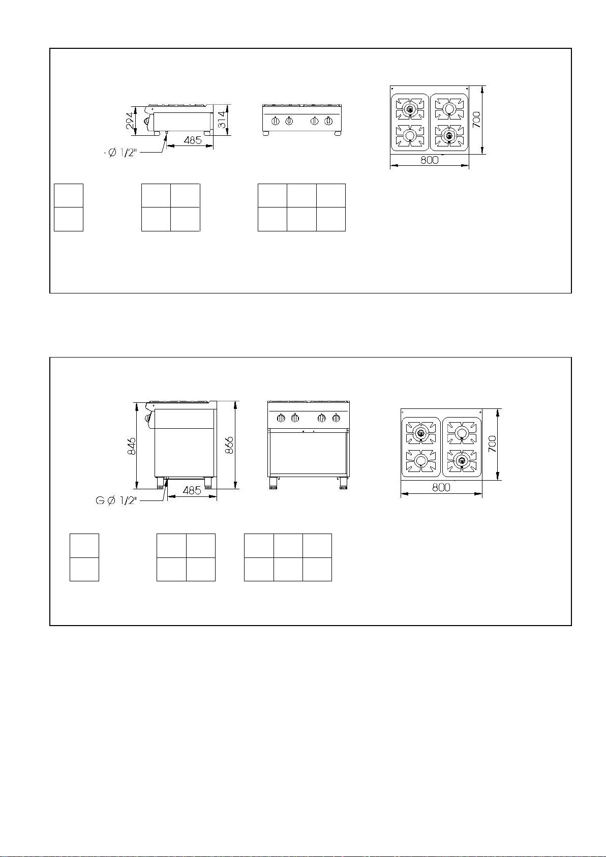
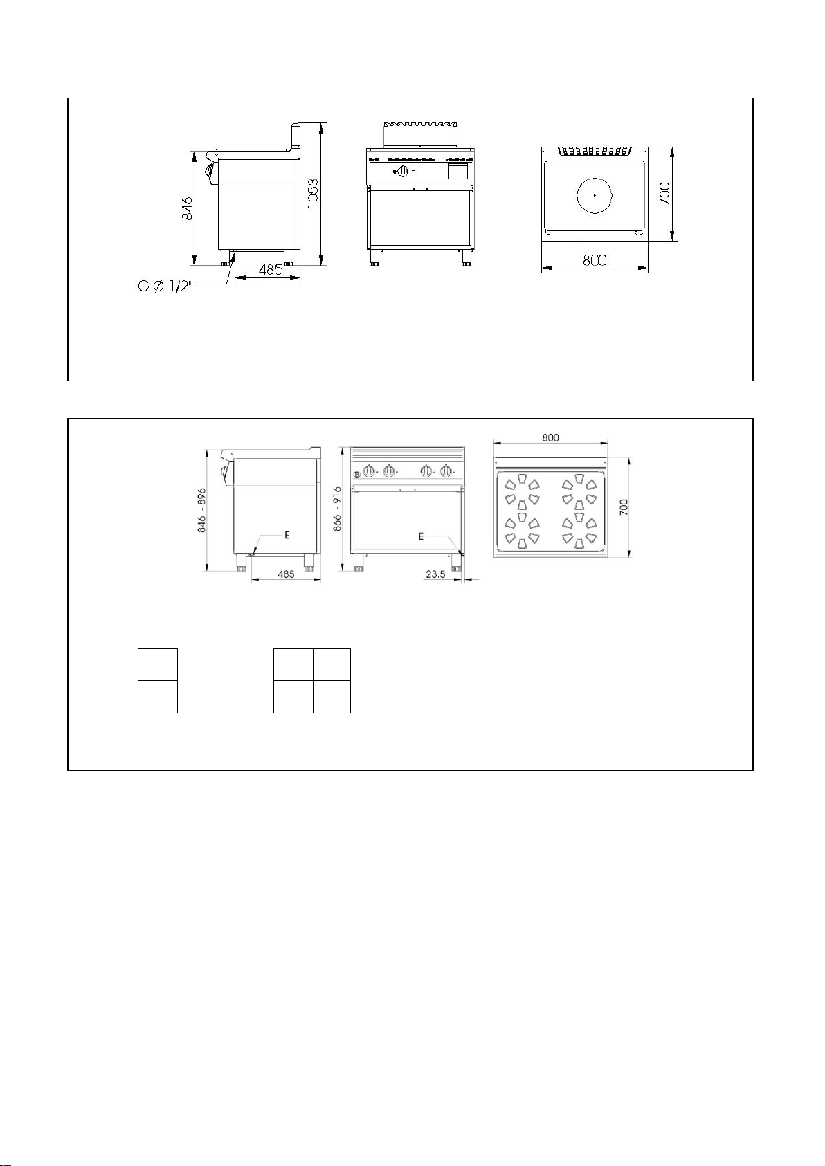
2891021 2891041 2891061
(G= gas\gaz)
Fig. – Abb. 1: Dimensioni \ Dimensions \ Floor space dimensions \ Raumbedarfsmasse \ Espacio máximo necesario
2851021 2851041 2851061
(G= gas \ gaz)
Fig. – Abb. 2: Dimensioni \ Dimensions \ Floor space dimensions \ Raumbedarfsmasse \ Espacio máximo necesario
Pag. 3/118
Page 4
D C D C D
C D C D C
D C D C D
C D C D C
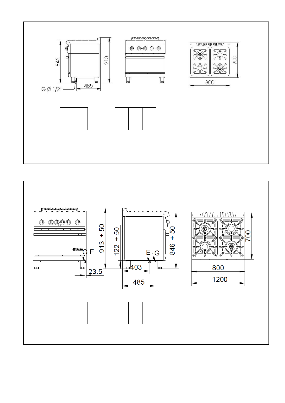
2852341 2852361
(G= gas \ gaz)
Fig. – Abb. 3: Dimensioni \ Dimensions \ Floor space dimensions \ Raumbedarfsmasse \ espacio máximo necesario
2852251 2852471
(G= gas \ gaz ; E= elettrico \ électrique \ electric\ Elektrisch \ eléctrico)
Fig. – Abb. 4: Dimensioni \ Dimensions \ Floor space dimensions \ Raumbedarfsmasse \ espacio máximo necesario
Pag. 4/118
Page 5
D C D C D C D C D C
D C D
C D C
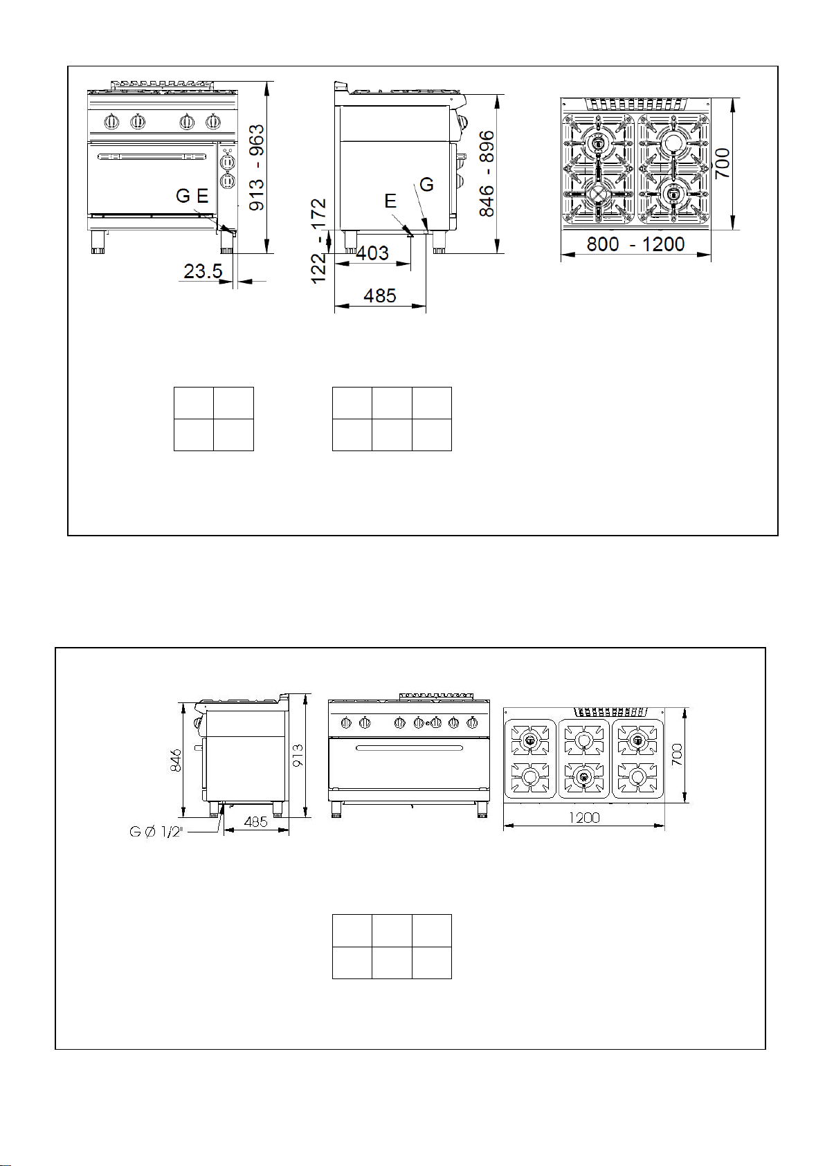
2852241 2852461
(G= gas \ gaz ; E= elettrico \ électrique \ electric\ Elektrisch \ eléctrico)
Fig. – Abb. 5: Dimensioni \ Dimensions \ Floor space dimensions \ Raumbedarfsmasse \ espacio máximo necesario
2852261
(G= gas \ gaz )
Fig. – Abb. 6: Dimensioni \ Dimensions \ Floor space dimensions \ Raumbedarfsmasse \ espacio máximo necesario
Pag. 5/118
Page 6

2,6
2,6
2,6
2,6
2,6
2,6 2,6
2,6
2,6
2,6
2,6
2,6 2,6
2,6
2,6
2,6
2,6
2,6 2,6
2,6
2,6
2,6
2,6
2,6
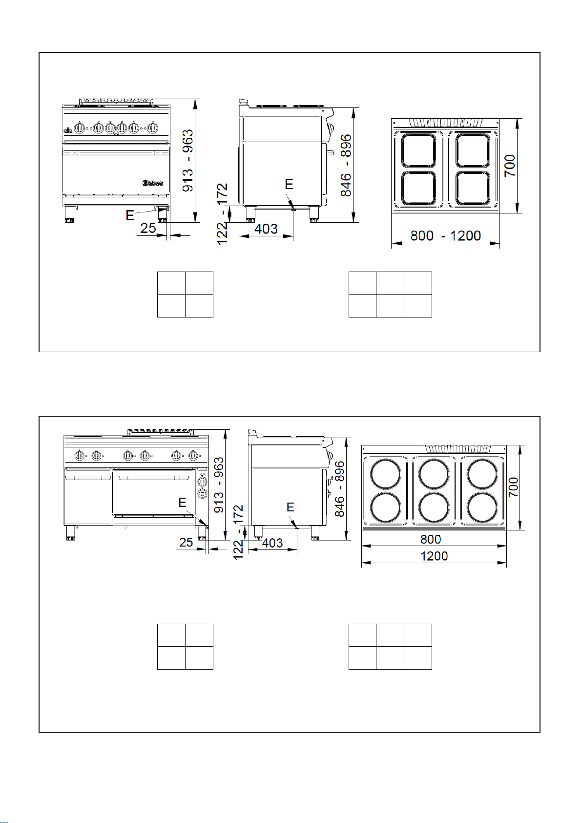
288102 288104 288106
(E= elettrico \ électrique \ electric\ Elektrisch \ eléctrico)
Fig. – Abb. 7: Dimensioni \ Dimensions \ Floor space dimensions \ Raumbedarfsmasse \ espacio máximo necesario
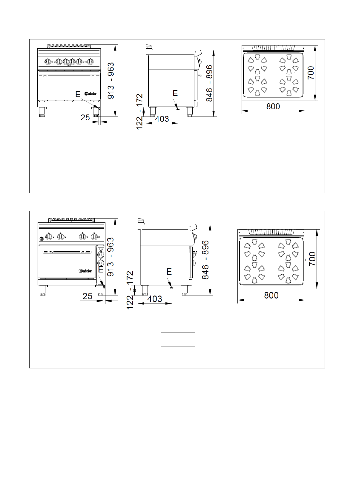
286102 286104 286106
286103 286325 286356
(E= elettrico \ électrique \ electric\ Elektrisch \ eléctrico)
Fig. – Abb. 8: Dimensioni \ Dimensions \ Floor space dimensions \ Raumbedarfsmasse \ espacio máximo necesario
Pag. 6/118
Page 7
2,6
2,6 2,6
2,6
2,6
2,6
2,6 2,6
2,6
2,6
2,6
2,6 2,6
2,6
2,6
2,6
2,6 2,6
2,6
2,6
286234W 286256W
(E= elettrico \ électrique \ electric\ Elektrisch \ eléctrico)
Fig. – Abb. 9: Dimensioni \ Dimensions \ Floor space dimensions \ Raumbedarfsmasse \ espacio máximo necesario
286224W 286246W
286324W 286346W
(E= elettrico \ électrique \ electric\ Elektrisch \ eléctrico)
Fig. – Abb. 10: Dimensioni \ Dimensions \ Floor space dimensions \ Raumbedarfsmasse \ espacio máximo necesario
Pag. 7/118
Page 8
2857001
(G= gas\gaz)
2,3
2,3
2,3 2,3
2,3
2,3
Fig. – Abb. 11: Dimensioni \ Dimensions \ Floor space dimensions \ Raumbedarfsmasse \ espacio máximo necesario
287410 287420
(E= elettrico \ électrique \ electric\ Elektrisch)
Fig. – Abb. 12: Dimensioni \ Dimensions \ Floor space dimensions \ Raumbedarfsmasse
Pag. 8/118
Page 9
2,3
2,3
2,3
2,3
2,3
2,3
2,3
2,3
287440
(E= elettrico \ électrique \ electric\ Elektrisch)
Fig. – Abb. 13: Dimensioni \ Dimensions \ Floor space dimensions \ Raumbedarfsmasse
287430W
(E= elettrico \ électrique \ electric\ Elektrisch)
Fig. – Abb. 14: Dimensioni \ Dimensions \ Floor space dimensions \ Raumbedarfsmasse
Pag. 9/118
Page 10
E
G
100
100
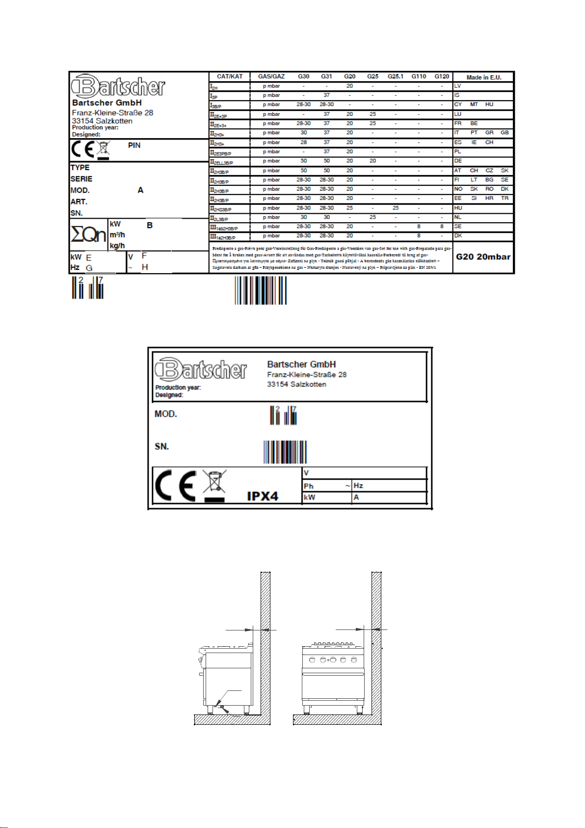
Fig. – Abb. 15: targhetta caratteristiche machine a gas\ Plaques des caractéristiques \ gas data plate\ Typenschild \
Chapa características cocinas gas
Fig. – Abb. 17: targhetta caratteristiche macchine elettriche\ Plaques des caractéristiques appareils électriques \ data
plate electric appliances \ Typenschild Elektro-Geräte \ Chapa características cocinas electricas
Fig. – Abb. 18: Installazione \ Lieu d'installation \ Place \ Installationsort \ Lugar
Pag. 10/118
Page 11
2
1800
1
2
2
3
3
4
7
6
5
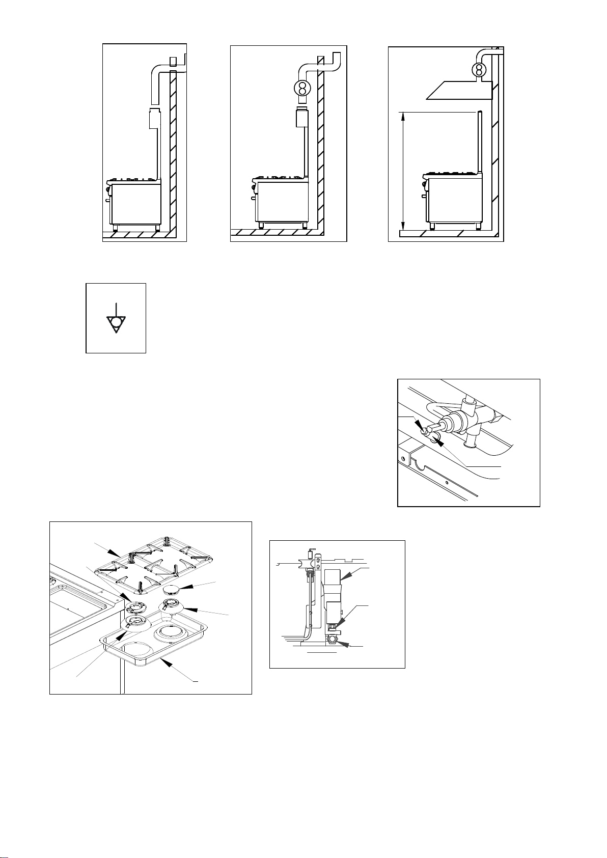
Figg. – Abb. 19, 20 , 21:Scarico fumi \ Évacuation des fumées \ Fumes evacuation \ Rauchabzug \ Descarga
Fig. – Abb. 22: Simbolo
equipotenziale \ Symbole
equipotenziel \
Equipotenziale label \
Äquipotenzial Symbol \
Equipotencial símbolo
Fig. – Abb. 23: Verifica della tenuta e della pressione di
alimentazione \ Contrôle de la tenue et de la pression d'alimentation
\ Checking gas tightness and pressure \ Überprüfung der Dichtigkeit
und des Versorgungsdrucks \ Comprobación de la estanqueidad y de
la presión de alimentación
Figg.. – Abb. 24, 25 :
Sostituzione ugello bruciatore \
Changement du gicleur du
brûleur \ Substituting the burner
nozzle \ Austausch der
Hauptbrennerdüse \ Cambio
boquilla quemador
Pag. 11/118
Page 12
8
x
9
1
1
2
1
2
1
2
3
4
5
3
Fig. – Abb. 26 : Regolazione dell’aria primaria bruciatore \
Réglage de l'air primaire du brûleur \ Regulating the primary air
of the burner \ Primärluftregelung des Hauptbrenners \
Regulación del aire primario quemador
Fig. – Abb. 29 : Sostituzione dell’ugello bruciatore pilota \
Changement du gicleur du brûleur veilleuse \ Substituting the pilot
burner nozzle \ Austausch der Zündbrennerdüse \ Cambio de la
boquilla del quemador piloto
Figg. – Abb. 27, 28 : Sostituzione del By-Pass \
Changement du by-pass \ Substituting the By-Pass \
Austausch des By-Pass \ Cambio del by-pass
Figg. – Abb. 30 , 31: Sostituzione ugello bruciatore \ Changement du gicleur du brûleur \ Substituting the burner nozze\
Austausch der Hauptbrennerdüse \ Cambio boquilla quemador
Pag. 12/118
Page 13
6
3
X
5
6
1
1
2
3
4
7
1
1
2
A
1
2
3
4
Fig. – Abb. 32 : Regolazione
dell’aria primaria bruciatore \
Réglage de l'air primaire du
brûleur \ Regulating the primary
air of the burner \
Primärluftregelung des
Hauptbrenners \ Regulación del
aire primario quemador
Fig. – Abb. 33: Sostituzione del By-Pass \ Changement du by-pass \
Substituting the by-pass \ Austausch des By-Pass \ Cambio del bypass
Figg. – Abb. 34, 35: Sostituzione dell’ugello bruciatore pilota\ Changement du gicleur du brûleur de veilleuse\
Substituting the pilot burner nozzle\ Austausch der Zündbrennerdüse \ Cambio de la boquilla del quemador piloto
Pag. 13/118
Page 14
1
2
3
4
5
6
7
x
1
2
1
1
2
3
4
Figg. – Abb. 36 , 37: Sostituzione ugello bruciatore \ Changement du gicleur du brûleur \ Substituting the burner nozze\
Austausch der Hauptbrennerdüse \ Cambio boquilla quemador
Fig. – Abb. 38 : Regolazione dell’aria primaria bruciatore \ Réglage de l'air
primaire du brûleur \ Regulating the primary air of the burner \
Primärluftregelung des Hauptbrenners \ Regulación del aire primario
quemador
Fig. – Abb. 39 : Regolazione del minimo \ Réglage
du minimum\ Regulation at minimum \ Regulierung
des kleinsten Flamme \ Regulación del mínimo
Figg. – Abb. 40 : Sostituzione dell’ugello bruciatore pilota\
Changement du gicleur du brûleur de veilleuse\ Substituting the
pilot burner nozzle\ Austausch der Zündbrennerdüse \ Cambio de la
boquilla del quemador piloto
Fig. – Abb. 41 : Istruzioni uso (Fuochi aperti) \ Instructions
d’utilisation (Feux ouverts) \ Instruction for use (open rings)
\ Bedienungsanleitungen (Offene Feuerstellen) \
Instrucciones de uso (Fogones abiertos)
Pag. 14/118
Page 15

1
2
3
4
Fig. – Abb. 42: Istruzioni uso (Forno) \ Instructions
d’utilisation (Four) \ Instruction for use (oven) \
Bedienungsanleitungen (backofen) \ Instrucciones de uso
(horno)
Fig. – Abb. 43 : Istruzioni uso (Tuttapiastra)\ Instructions
d’utilisation (Plaque Grill)\ Instruction for use (All hotplate)\
Bedienungsanleitungen (Grillplatte) \ Instrucciones de uso
(Planchas)
Fig. – Abb. 44 : Istruzioni uso (Piastre elettriche) \ Instructions
d’utilisation (Plaque électrique ) \ Instruction for use (Electric
hotplates) \ Bedienungsanleitungen (Elektroplatten) \
Instrucciones de uso (Placas eléctricas)
Fig. – Abb. 45 : Istruzioni uso (Forno elettrico
ventilato) \ Instructions d’utilisation (Four électrique
ventilé ) \ Instruction for use (Electric ventilated oven) \
Bedienungsanleitungen (Elektrobackofen mit Umluft) \
Instrucciones de uso (Horno eléctrico ventilado)
Fig. – Abb. 46 : Allacciamento elettrico per forno elettrico
ventilato \ Branchement électrique pour four électrique ventilé
\ Electric feeding for electric ventilated oven \ Elektrischer
Anschluss für den elektrischen Backofen mit Belüftung \
Conexión eléctrica para horno ventilado
Pag. 15/118
Page 16

5
5
5
5
6
1
1
1
1
2
3
4
1
2
2
3
1
1
2
34
5
Figg. – Abb. 47,48 : Sostituzione del motore del forno elettrico ventilato) \ Changement du moteur du four électrique
ventilé \ Substituting the motor of the ventilated electric oven\ Austausch der Motor vom Elektobackofen mit Umluft\
Cambio motor del Horno eléctrico ventilado
Fig. – Abb. 49 : Sostituzione componenti elettrici di comando del forno
elettrico ventilato \ Remplacement composants électriques de contrôle du
four électrique ventilé \ Replacement of electric components of the
ventilated oven.
\ Ersetzen von elektrischen Komponenten der Steuerung des elektrischen
Backofens mit Umluft \ Sustitución componentes eléctricos de control del
horno eléctrico ventilado
Fig. – Abb. 50 : Sostituzione delle resistenze elettriche del forno
elettrico ventilato\ Remplacement de résistances électriques du four
électrique ventilé\ Replacement of the heating elements in the electric
ventilated oven \ Ersetzen der elektrischen Widerstände des
elektrischen Backofens mit Umluft
\ Sustitución de las resistencias eléctricas del horno ventilado.
Fig. – Abb. 51 : Istruzioni uso (Forno elettrico) \ Instructions d’utilisation (Four
électrique ) \ Instruction for use (Electric oven) \ Bedienungsanleitungen
(Elektrobackofen) \ Instrucciones de uso (Horno eléctrico)
Pag. 16/118
Page 17

Fig. – Abb. 52 : Allacciamento elettrico per forno elettrico \
Branchement électrique pour four électrique ventilé
\ Electric feeding for electric oven \ Elektrischer Anschluss
für den elektrischen Backofen \ Conexión eléctrica para
horno
Fig. – Abb. 54 : Sostituzione delle resistenze
elettriche del forno elettrico \ Remplacement de
résistances électriques du four électrique \
Replacement of the heating elements in the electric
oven \ Ersetzen der elektrischen Widerstände des
elektrischen Backofens \ Sustitución de las
resistencias eléctricas del horno
Fig. – Abb. 55 : Sostituzione ugello bruciatore \ Changement du
gicleur du brûleur \ Substituting the burner nozze\ Austausch der
Hauptbrennerdüse \ Cambio boquilla quemador
Fig. – Abb. 53 : Sostituzione componenti elettrici di
comando del forno elettrico \ Remplacement
composants électriques de contrôle du four électrique\
Replacement of electric components of the oven.
\ Ersetzen von elektrischen Komponenten der
Steuerung des elektrischen Backofens \ Sustitución
componentes eléctricos de control del horno eléctrico
ventilado
Pag. 17/118
Page 18

Fig. – Abb. 56: Regolazione dell’aria primaria bruciatore \ Réglage de l'air
primaire du brûleur \ Regulating the primary air of the burner \
Primärluftregelung des Hauptbrenners \ Regulación del aire primario
quemador
Figg. – Abb. 57,58,59: Sostituzione del bruciatore pilota \
Changement du brûleur veilleuse \ Substituting the pilot
burner \ Austausch der Zündbrenner \ Cambio del
quemador piloto
Fig. – Abb. 60 : Istruzioni uso (cucina vetroceramica) \ Instructions
d’utilisation (\ fourneaux vitrocéramique) \ Instruction for use (glass
ceramic) \ Bedienungsanleitungen (Ceranherde)
Fig. – Abb. 61 : manopola \ sélecteur \ knob \ Knopf
Pag. 18/118
Page 19

Pag. 66/118
Model
Description
Dimensions
LxPxH [mm]
Gas
output
(B)
[Kw]
Type
(A)
LPG
Consumption
(G30)
(D)
[Kg/h]
METHANE
Consumption
(G20)
(C)
[m3/h]
Air for
comb.
[m3/h]
Gas fitting
Electric
power
(E)
[Kw]
Tension
(F)
[V]
Freq.
(G)
[Hz]
Cable type
H07 RN-F
[mm2]
Burner
C
3.6
kW
[N°]
Burner
D
5.5
kW
[N°]
Burner
E
8
kW
[N°]
Oven
G
7,55
kW
[N°]
Oven
H
13.5
kW
[N°]
All
H.P.
11,5
kW
[N°]
Oven
E. V.
3,65
kW
[N°]
Oven
E.
5,4
kW
[N°]
H.P.
E.
2,6
kW
[N°]
Heater
2.3
kW
[N°]
2891021
Cooker 2 gas rings top
400x700x295
9,1
A1
0,717
0,963
18,2
UNI-ISO 7/1 R ½
-
- - 1
1
- - -
- - -
-
-
2891041
Cooker 4 gas rings top
800x700x295
18,2
A1
1,435
1,926
36,4
UNI-ISO 7/1 R ½
-
- - 2
2
- - -
- - -
-
-
2891061
Cooker 6 gas rings top
1200x700x295
27,3
A1
2,153
2,889
54,6
UNI-ISO 7/1 R ½
-
- - 3
3
- - -
- - -
-
-
2851021
Cooker 2 gas rings on cabinet
400x700x845
9,1
A1
0.717
0,963
18,2
UNI-ISO 7/1 R ½
-
- - 1
1
- - -
- - -
-
-
2851041
Cooker 4 gas rings on cabinet
800x700x845
18,2
A1
1.435
1,926
36,4
UNI-ISO 7/1 R ½
-
- - 2
2
- - -
- - -
-
-
2851061
Cooker 6 gas rings on cabinet
1200x700x845
27,3
A1
2.153
2,889
54,6
UNI-ISO 7/1 R ½
-
- - 3
3
- - -
- - -
-
-
2852341
Cooker 4 gas rings on gas
oven
800x700x845
25,75
A1/B1
1
2,058
2,724
52,2
UNI-ISO 7/1 R ½
-
- - 2
2
- 1 -
- - -
-
-
2852361
Cooker 6 gas rings on gas
oven
1200x700x845
34,85
A1/B1
1
2,775
3,687
70,4
UNI-ISO 7/1 R ½
-
- - 3
3
- 1 -
- - -
-
-
2852261
Cooker 6 gas rings on gas
maxi oven
1200x700x845
40,8
A1
3,218
4,317
81,6
UNI-ISO 7/1 R ½
-
- - 3
3
-
-
1
- - -
-
-
2852251
Cooker 4 gas rings on electric
oven
800x700x845
18,2
A1
0,717
0,963
18,2
UNI-ISO 7/1 R ½
5,4
230 1 -
400 3N
50/60
4x2.5 -
5x1.5
2
2
- - -
-
-
1
-
-
2852471
Cooker 6 gas rings on electric
oven
1200x700x845
27,3
A1
1,435
1,926
36,4
UNI-ISO 7/1 R ½
5,4
230 1 -
400 3N
50/60
4x2.5 -
5x1.5
3
3
- - -
-
-
1
-
-
2852241
Cooker 4 gas rings on
ventilated electric oven
800x700x845
18,2
A1
0,717
0,963
18,2
UNI-ISO 7/1 R ½
3,65
230 1 -
400 3N
50
3x2,5 –
5x1
2
2
- - -
- 1 -
-
-
2852461
Cooker 6 gas rings on
ventilated electric oven
1200x700x845
27,3
A1
1,435
1,926
36,4
UNI-ISO 7/1 R ½
3,65
230 1 -
400 3N
50
3x2,5 –
5x1
3
3
- - -
- 1 -
-
-
2857001
All hotplate on cabinet
800x700x845
11,5
A1
0,907
1,216
23
UNI-ISO 7/1 R ½
-
- - -
-
-
- - -
1
-
-
-
-
288102
Top electric range 2 plates
400x700x295
-
-
-
-
-
-
5,2
400 3N
50/60
5x1,5
-
-
- - -
- - -
2
-
288104
Top electric range 4 plates
800x700x295
-
-
-
-
-
-
10,4
400 3N
50/60
5x2,5
-
-
- - -
- - -
4
-
288106
Top electric range 6 plates
1200x700x295
-
-
-
-
-
-
15,6
400 3N
50/60
5x4
-
-
- - -
- - -
6
-
286102
Top electric range 2 plates on
open cabinet
400x700x845
-
-
-
-
-
-
5,2
400 3N
50/60
5x1,5
-
-
- - -
- - -
2
-
286103
Top electric range 2 square
plates on open cabinet
400x700x845
-
-
-
-
-
-
5,2
400 3N
50/60
5x1,5
-
-
- - -
- - -
2
-
286104
Top electric range 4 plates on
open cabinet
800x700x845
-
-
-
-
-
-
10,4
400 3N
50/60
5x2,5
-
-
- - -
- - -
4
-
286325
Top electric range 4 square
plates on open cabinet
800x700x845
-
-
-
-
-
-
10,4
400 3N
50/60
5x2,5
-
-
- - -
- - -
4
-
286106
Top electric range 6 plates on
open cabinet
1200x700x845
-
-
-
-
-
-
15,6
400 3N
50/60
5x4
-
-
- - -
- - -
6
-
286356
Top electric range 6 square
plates on open cabinet
1200x700x845
-
-
-
-
-
-
15,6
400 3N
50/60
5x4
-
-
- - -
- - -
6
-
286234W
Top electric range 4 plates on
electric oven
800x700x845
-
-
-
-
-
-
15,8
400 3N
50/60
5x6
-
-
- - -
-
-
1
4
-
286256W
Top electric range 6 plates on
electric oven
1200x700x845
-
-
-
-
-
21
400 3N
50/60
5x10
-
-
- - -
-
-
1
6
-
286224W
Top electric range 4 plates on
ventilated electric oven
800x700x845
-
-
-
-
-
14
400 3N
50
5x4
-
-
- - -
- 1 -
4
-
286246W
Top electric range 6 plates on
ventilated electric oven
1200x700x845
-
-
-
-
-
-
19,2
400 3N
50
5x6
-
-
- - -
- 1 -
6
-
286324W
Top electric range 4 square
plates on ventilated electric
oven
800x700x845
-
-
-
-
-
14
400 3N
50
5x4
-
-
- - -
- 1 -
4
-
286346W
Top electric range 6 square
plates on ventilated electric
oven
1200x700x845
-
-
-
-
-
-
19,2
400 3N
50
5x6
-
-
- - -
- 1 -
6
-
(Table 1) TECHNICAL FEATURES
(LV-IS-CY-MT-HU-PL-GR-GB-IE -CZ-SK-FI-LT-BG-SE-DK-NO -RO-EE-SI-HR-TR-NL)
Page 20

Model
Description
Dimensions
LxPxH [mm]
Gas
output
(B)
[Kw]
Type
(A)
LPG
Consumption
(G30)
(D)
[Kg/h]
METHANE
Consumption
(G20)
(C)
[m3/h]
Air for
comb.
[m3/h]
Gas fitting
Electric
power
(E)
[Kw]
Tension
(F)
[V]
Freq.
(G)
[Hz]
Cable type
H07 RN-F
[mm2]
Burner
C
3.6
kW
[N°]
Burner
D
5.5
kW
[N°]
Burner
E
8
kW
[N°]
Oven
G
7,55
kW
[N°]
Oven
H
13.5
kW
[N°]
All
H.P.
11,5
kW
[N°]
Oven
E. V.
3,65
kW
[N°]
Oven
E.
5,4
kW
[N°]
H.P.
E.
2,6
kW
[N°]
Heater
2.3
kW
[N°]
287410
Glass ceramic electric range 2
plates on open cabinet
400x700x845
-
-
-
-
-
-
4,6
400 3N
50/60
5x1,5
-
-
- - -
- - -
-
2
287420
Glass ceramic electric range 2
plates on open cabinet
800x700x845
-
-
-
-
-
-
8,2
400 3N
50/60
5x2,5
-
-
- - -
- - -
-
4
287440W
Glass ceramic electric range 4
plates on electric oven
800x700x845
-
-
-
-
-
-
14,6
400 3N
50/60
5x4
-
-
- - -
-
-
1
-
4
287430W
Glass ceramic electric range 4
plates on el. ventilated oven
800x700x845
-
-
-
-
-
-
11,85
400 3N
50
5x4
-
-
- - -
- 1 -
-
4
)
Gas Type
Normal
Capacity
[kW]
Reduced
Capacity
[kW]
Diam. Main
Injector [1/100
mm]
By-pass
Diameter
[1/100 mm]
Pilot
Injectors
[N°]
Air
Regulation
“x” [mm]
BURNER C Ø 85
Natural Methane Gas
3,6
1,4
140
85
35
0,0
(G20)
BURNER D Ø 110
Natural Methane Gas
5,5
1,8
175
100
35
2,0
(G20)
BURNER E Ø 130
Natural Methane Gas
8,0
2,4
210
105
35
25,0
(G20)
ALL HOTPLATE BURNER
Natural Methane Gas
11,5
3,6
260
Reg.
27,2
1,0
(G20)
OVEN BURNER WITH TAP
Natural Methane Gas
7,55
1,9
200R
105
27,2
3,0
(G20)
OVEN BURNER WITH VALVE
Natural Methane Gas
7,55
200R
27,2
3,0
(G20)
MAXI OVEN BURNER
Natural Methane Gas
13,5
AL 285
-
27
25,0
(G20)
2H
Pag. 67/118
(LV - CAT. I
(Table 2) BURNER FEATURES
Page 21

(Table 3) BURNER FEATURES
Gas Type
Normal
Capacity
[kW]
Reduced
Capacity
[kW]
Diam. Main
Injector [1/100
mm]
By-pass
Diameter
[1/100 mm]
Pilot
Injectors
[N°]
Air
Regulation
“x” [mm]
BURNER C Ø 85
Liquid Gas PLG
3,6
1,4
95
58
20
2,0
(G31)
BURNER D Ø 110
Liquid Gas PLG
5,5
1,8
120
65
20
9,0
(G31)
BURNER E Ø 130
Liquid Gas PLG
(G31)
ALL HOTPLATE BURNER
Liquid Gas PLG
11,5
3,6
170
100
16,2
3,0
(G31)
OVEN BURNER WITH TAP
Liquid Gas PLG
7,9
1,9
AL 140
70
16,2
open
(G31)
OVEN BURNER WITH VALVE
Liquid Gas PLG
7,9
-
AL 140
-
16,2
open
(G31)
MAXI OVEN BURNER
Liquid Gas PLG
13,5
-
AL 190
-
19
39,0
(G31)
Gas Type
Normal
Capacity
[kW]
Reduced
Capacity
[kW]
Diam. Main
Injector [1/100
mm]
By-pass
Diameter
[1/100 mm]
Pilot
Injectors
[N°]
Air
Regulation
“x” [mm]
BURNER C Ø 85
Liquid Gas PLG
3,6
1,4
95
58
20
2,0
(G30-G31)
BURNER D Ø 110
Liquid Gas PLG
5,5
1,8
120
65
20
9,0
(G30-G31)
BURNER E Ø 130
Liquid Gas PLG
(G30-G31)
ALL HOTPLATE BURNER
Liquid Gas PLG
11,5
3,6
170
100
16,2
3,0
(G30-G31)
OVEN BURNER WITH TAP
Liquid Gas PLG
7,9
1,9
AL 140
70
16,2
open
(G30-G31)
OVEN BURNER WITH VALVE
Liquid Gas PLG
7,9
-
AL 140
-
16,2
open
(G30-G31)
MAXI OVEN BURNER
Liquid Gas PLG
13,5
-
AL 190
-
19
39,0
(G30-G31)
(IS - CAT. I3P)
(Table 4) BURNER FEATURES
(CY, MT, HU(only K7GCU15FFM) - CAT. I
3B/P 29mbar
)
Pag. 69/118
Page 22

(Table 5) BURNER FEATURES
Gas Type
Normal
Capacity
[kW]
Reduced
Capacity
[kW]
Diam. Main
Injector [1/100
mm]
By-pass
Diameter
[1/100 mm]
Pilot
Injectors
[N°]
Air
Regulation
“x” [mm]
BURNER C Ø 85
Natural Methane Gas
3,6
1,4
130
85
35
0,0
(G20)
Natural Methane Gas
3,6
1,4
140R
85
35
0,0
(G25.1)
Liquid Gas PLG
3,6
1,4
95
58
20
2,0
(G30-G31)
BURNER D Ø 110
Natural Methane Gas
5,5
1,8
165
100
35
2,0
(G20)
Natural Methane Gas
5,5
1,8
185
100
35
0,0
(G25.1)
Liquid Gas PLG
5,5
1,8
120
65
20
9,0
(G30-G31)
BURNER E Ø 130
Natural Methane Gas
8,0
2,4
195
105
35
25,0
(G20)
Natural Methane Gas
8,0
2,4
220
105
35
4,0
(G25.1)
Liquid Gas PLG
(G30-G31)
ALL HOTPLATE BURNER
Natural Methane Gas
11,5
3,6
240
Reg.
27,2
1,0
(G20)
Natural Methane Gas
11,5
3,6
270
Reg.
27,2
1,0
(G25.1)
Liquid Gas PLG
11,5
3,6
170
100
16,2
3,0
(G30-G31)
OVEN BURNER WITH TAP
Natural Methane Gas
7,55
1,9
185R
100
27,2
3,0
(G20)
Natural Methane Gas
7,55
1,9
210R
110
27,2
3,0
(G25.1)
Liquid Gas PLG
7,9
1,9
AL 140
70
16,2
open
(G30-G31)
OVEN BURNER WITH VALVE
Natural Methane Gas
7,55
-
185R
-
27,2
3,0
(G20)
Natural Methane Gas
7,55
-
210R
27,2
3,0
(G25.1)
Liquid Gas PLG
7,9
-
AL 140
-
16,2
open
(G30-G31)
(HU(K7GCU15FFM EXCEPTED) - CAT. II
HS3B/P 30mbar
)
Pag. 70/118
Page 23

(Table 6) BURNER FEATURES
Gas Type
Normal
Capacity
[kW]
Reduced
Capacity
[kW]
Diam. Main
Injector [1/100
mm]
By-pass
Diameter
[1/100 mm]
Pilot
Injectors
[N°]
Air
Regulation
“x” [mm]
BURNER C Ø 85
Natural Methane Gas
3,6
1,4
130
85
35
0,0
(G20)
Natural Methane Gas
3,6
1,4
140R
85
35
0,0
(G25.1)
Liquid Gas PLG
3,6
1,4
80
55
20
0,0
(G30-G31)
BURNER D Ø 110
Natural Methane Gas
5,5
1,8
165
100
35
2,0
(G20)
Natural Methane Gas
5,5
1,8
185
100
35
0,0
(G25.1)
Liquid Gas PLG
5,5
1,8
105
65
20
6,0
(G30-G31)
BURNER E Ø 130
Natural Methane Gas
8,0
2,4
195
105
35
25,0
(G20)
Natural Methane Gas
8,0
2,4
220
105
35
4,0
(G25.1)
Liquid Gas PLG
(G30-G31)
ALL HOTPLATE BURNER
Natural Methane Gas
11,5
3,6
240
Reg.
27,2
1,0
(G20)
Natural Methane Gas
11,5
3,6
270
Reg.
27,2
1,0
(G25.1)
Liquid Gas PLG
11,5
3,6
150
85
16,2
2,0
(G30-G31)
OVEN BURNER WITH TAP
Natural Methane Gas
7,55
1,9
185R
100
27,2
3,0
(G20)
Natural Methane Gas
7,55
1,9
210R
110
27,2
3,0
(G25.1)
Liquid Gas PLG
7,9
1,9
AL 120
60
16,2
4,0
(G30-G31)
OVEN BURNER WITH VALVE
Natural Methane Gas
7,55
-
185R
-
27,2
3,0
(G20)
Natural Methane Gas
7,55
-
210R
27,2
3,0
(G25.1)
Liquid Gas PLG
7,9
-
AL 120
-
16,2
4,0
(G30-G31)
(HU(K7GCU15FFM Excepted) - CAT. II
HS3B/P 50mbar
)
Pag. 71/118
Page 24

(Table 7) BURNER FEATURES
Gas Type
Normal
Capacity
[kW]
Reduced
Capacity
[kW]
Diam. Main
Injector [1/100
mm]
By-pass
Diameter
[1/100 mm]
Pilot
Injectors
[N°]
Air
Regulation
“x” [mm]
BURNER C Ø 85
Natural Methane Gas
3,6
1,4
140
85
35
0,0
(G20)
Liquid Gas PLG
3,6
1,4
95
58
20
2,0
(G30-G31)
BURNER D Ø 110
Natural Methane Gas
5,5
1,8
175
100
35
2,0
(G20)
Liquid Gas PLG
5,5
1,8
120
65
20
9,0
(G30-G31)
BURNER E Ø 130
Natural Methane Gas
8,0
2,4
210
105
35
25,0
(G20)
Liquid Gas PLG
(G30-G31)
ALL HOTPLATE BURNER
Natural Methane Gas
11,5
3,6
260
Reg.
27,2
1,0
(G20)
Liquid Gas PLG
11,5
3,6
170
100
16,2
3,0
(G30-G31)
OVEN BURNER WITH TAP
Natural Methane Gas
7,55
1,9
200R
105
27,2
3,0
(G20)
Liquid Gas PLG
7,9
1,9
AL 140
70
16,2
open
(G30-G31)
OVEN BURNER WITH VALVE
Natural Methane Gas
7,55
-
200R
-
27,2
3,0
(G20)
Liquid Gas PLG
7,9
-
AL 140
-
16,2
open
(G30-G31)
MAXI OVEN BURNER
Natural Methane Gas
13,5
-
AL 285
-
27
25,0
(G20)
Liquid Gas PLG
13,5
-
AL 190
-
19
39,0
(G30-G31)
(PL - CAT. II
2E3PB/P
)
Pag. 72/118
Page 25

(Table 8) BURNER FEATURES
Gas Type
Normal
Capacity
[kW]
Reduced
Capacity
[kW]
Diam. Main
Injector [1/100
mm]
By-pass
Diameter
[1/100 mm]
Pilot
Injectors
[N°]
Air
Regulation
“x” [mm]
BURNER C Ø 85
Natural Methane Gas
3,6
1,4
140
85
35
0,0
(G20)
Liquid Gas PLG
3,6
1,4
95
58
20
2,0
(G30-G31)
BURNER D Ø 110
Natural Methane Gas
5,5
1,8
175
100
35
2,0
(G20)
Liquid Gas PLG
5,5
1,8
120
65
20
9,0
(G30-G31)
BURNER E Ø 130
Natural Methane Gas
8,0
2,4
210
105
35
25,0
(G20)
Liquid Gas PLG
(G30-G31)
ALL HOTPLATE BURNER
Natural Methane Gas
11,5
3,6
260
Reg.
27,2
1,0
(G20)
Liquid Gas PLG
11,5
3,6
170
100
16,2
3,0
(G30-G31)
OVEN BURNER WITH TAP
Natural Methane Gas
7,55
1,9
200R
105
27,2
3,0
(G20)
Liquid Gas PLG
7,9
1,9
AL 140
70
16,2
open
(G30-G31)
OVEN BURNER WITH VALVE
Natural Methane Gas
7,55
-
200R
-
27,2
3,0
(G20)
Liquid Gas PLG
7,9
-
AL 140
-
16,2
open
(G30-G31)
MAXI OVEN BURNER
Natural Methane Gas
13,5
-
AL 285
-
27
25,0
(G20)
Liquid Gas PLG
13,5
-
AL 190
-
19
39,0
(G30-G31)
(GR, GB, IE, ES - CAT. II
2H3+
)
Pag. 73/118
Page 26

(Table 9) BURNER FEATURES
Gas Type
Normal
Capacity
[kW]
Reduced
Capacity
[kW]
Diam. Main
Injector [1/100
mm]
By-pass
Diameter
[1/100 mm]
Pilot
Injectors
[N°]
Air
Regulation
“x” [mm]
BURNER C Ø 85
Natural Methane Gas
3,6
1,4
140
85
35
0,0
(G20)
Liquid Gas PLG
3,6
1,4
80
55
20
0,0
(G30-G31)
BURNER D Ø 110
Natural Methane Gas
5,5
1,8
175
100
35
2,0
(G20)
Liquid Gas PLG
5,5
1,8
105
65
20
6,0
(G30-G31)
BURNER E Ø 130
Natural Methane Gas
8,0
2,4
210
105
35
25,0
(G20)
Liquid Gas PLG
(G30-G31)
ALL HOTPLATE BURNER
Natural Methane Gas
11,5
3,6
260
Reg.
27,2
1,0
(G20)
Liquid Gas PLG
11,5
3,6
150
85
16,2
2,0
(G30-G31)
OVEN BURNER WITH TAP
Natural Methane Gas
7,55
1,9
200R
105
27,2
3,0
(G20)
Liquid Gas PLG
7,9
1,9
AL 120
60
16,2
4,0
(G30-G31)
OVEN BURNER WITH VALVE
Natural Methane Gas
7,55
-
200R
-
27,2
3,0
(G20)
Liquid Gas PLG
7,9
-
AL 120
-
16,2
4,0
(G30-G31)
MAXI OVEN BURNER
Natural Methane Gas
13,5
-
AL 285
-
27
25,0
(G20)
Liquid Gas PLG
13,5
-
AL 165
-
19
39
(G30-G31)
(CZ,SK - CAT. II
2H3B/P 50mbar
)
Pag. 74/118
Page 27

(Table 10) BURNER FEATURES
Gas Type
Normal
Capacity
[kW]
Reduced
Capacity
[kW]
Diam. Main
Injector [1/100
mm]
By-pass
Diameter
[1/100 mm]
Pilot
Injectors
[N°]
Air
Regulation
“x” [mm]
BURNER C Ø 85
Natural Methane Gas
3,6
1,4
140
85
35
0,0
(G20)
Liquid Gas PLG
3,6
1,4
95
58
20
2,0
(G30-G31)
BURNER D Ø 110
Natural Methane Gas
5,5
1,8
175
100
35
2,0
(G20)
Liquid Gas PLG
5,5
1,8
120
65
20
9,0
(G30-G31)
BURNER E Ø 130
Natural Methane Gas
8,0
2,4
210
105
35
25,0
(G20)
Liquid Gas PLG
(G30-G31)
ALL HOTPLATE BURNER
Natural Methane Gas
11,5
3,6
260
Reg.
27,2
1,0
(G20)
Liquid Gas PLG
11,5
3,6
170
100
16,2
3,0
(G30-G31)
OVEN BURNER WITH TAP
Natural Methane Gas
7,55
1,9
200R
105
27,2
3,0
(G20)
Liquid Gas PLG
7,9
1,9
AL 140
70
16,2
open
(G30-G31)
OVEN BURNER WITH VALVE
Natural Methane Gas
7,55
-
200R
-
27,2
3,0
(G20)
Liquid Gas PLG
7,9
-
AL 140
-
16,2
open
(G30-G31)
MAXI OVEN BURNER
Natural Methane Gas
13,5
-
AL 285
-
27
25,0
(G20)
Liquid Gas PLG
13,5
-
AL 190
-
19
39,0
(G30-G31)
(FI, LT, BG, SE, DK, NO, SK, RO, EE, SI, HR, TR - CAT.
II
2H3B/P 29mbar
)
Pag. 75/118
Page 28

(Table 11) BURNER FEATURES
Gas Type
Normal
Capacity
[kW]
Reduced
Capacity
[kW]
Diam. Main
Injector [1/100
mm]
By-pass
Diameter
[1/100 mm]
Pilot
Injectors
[N°]
Air
Regulation
“x” [mm]
BURNER C Ø 85
Natural Methane Gas
3,6
1,4
140
85
35
0,0
(G20)
Natural Methane Gas
3,6
1,4
145
85
35
0,0
(G25)
Liquid Gas PLG
3,6
1,4
95
58
20
2,0
(G30-G31)
BURNER D Ø 110
Natural Methane Gas
5,5
1,8
175
100
35
2,0
(G20)
Natural Methane Gas
5,5
1,8
180
100
35
2,0
(G25)
Liquid Gas PLG
5,5
1,8
120
65
20
9,0
(G30-G31)
BURNER E Ø 130
Natural Methane Gas
8,0
2,4
210
105
35
25,0
(G20)
Natural Methane Gas
8,0
2,4
215
105
35
9,0
(G25)
Liquid Gas PLG
(G30-G31)
ALL HOTPLATE BURNER
Natural Methane Gas
11,5
3,6
260
Reg.
27,2
1,0
(G20)
Natural Methane Gas
11,5
3,6
260
Reg.
27,2
1,0
(G25)
Liquid Gas PLG
11,5
3,6
170
100
16,2
3,0
(G30-G31)
OVEN BURNER WITH TAP
Natural Methane Gas
7,55
1,9
200R
105
27,2
3,0
(G20)
Natural Methane Gas
7,55
1,9
200R
105
27,2
3,0
(G25)
Liquid Gas PLG
7,9
1,9
AL 140
70
16,2
open
(G30-G31)
OVEN BURNER WITH VALVE
Natural Methane Gas
7,55
-
200R
-
27,2
3,0
(G20)
Natural Methane Gas
7,55
-
200R
-
27,2
3,0
(G25)
Liquid Gas PLG
7,9
-
AL 140
-
16,2
open
(G30-G31)
MAXI OVEN BURNER
Natural Methane Gas
13,5
-
AL 285
-
27
25,0
(G20)
Natural Methane Gas
13,5
-
AL 295
-
27
25,0
(G25)
Liquid Gas PLG
13,5
-
AL 190
-
19
39,0
(G30-G31)
(NL - CAT. II
2L3B/P
)
Pag. 76/118
Page 29

WARNINGS
General
Read the instructions carefully before installation, use and maintenance of the appliance.
The installation has to be performed by qualified personnel following the manufacturer’s
instructions given in the provided manual.
The appliance is only suitable for the preparation and cooking of food in industrial kitchens such
as those used in restaurants, hospitals, company canteens, cooking centres, butcher’s shops and
food production firms. Any other type of use is not in accordance with the intended purpose and
could place people and/or objects at risk.
The appliance is intended to be used EXCLUSIVELY with containers that are suitable for
contact with food and resistant to heat), any other use is not considered appropriate.
The appliance should only be used by trained personnel and for the use for which it was
designed.
Due to the nature of the appliance, the temperatures required for cooking may cause various
areas of the panelling, as well as kitchenware, to become hot. This is not a construction defect,
but a physical phenomenon caused by the chemical and physical properties of the materials used
for the construction of the appliances.
In the event of breakdown or malfunction, switch off the appliance and seek help exclusively
from an authorized technical assistance centre.
Only use genuine spare parts; otherwise no liability is assumed by the manufacturer.
The appliance must not be washed with high pressure water sprays and the vents or inlets/outlets
for air, fumes and heat must not be obstructed.
Before connecting the device make sure that the plate specifications correspond to the electrical
supply.
No appliance with a damaged glass ceramic hotplate (broken, cracked or split) should be used under
any circumstances, but should be brought immediately to an authorised technical assistance centre.
The ceramic glass cooker should not be used as a storage surface, since it could be accidentally
switched on and damage objects placed on it.
Ensure that no hard objects fall on the glass of the cooker, since, depending on the type of impact,
this could damage it.
When cooking, avoid placing pots and pans and/or crockery on the hotplate that are partially resting
on the stainless steel part of the hob, or the steel may overheat.
ATTENTION! The manufacturer declines any liability for damage caused by wrong
installation, tampering, making unauthorized changes, improper use, poor maintenance,
installation of non-original spare parts, not observing local norms, incorrect use or not
observing the instructions in this booklet
For the installer
The functioning of the appliance has to be explained and shown to the user. After ensuring that
everything is clear, the instruction booklet has to be handed over to the user.
The user has to be informed that any building modification or restructuring that may in any way
modify the air supply necessary for combustion makes it necessary to carry out another check of
the functionality of the appliance.
Pag. 77/118
Page 30

TECHNICAL FEATURES
The following instructions for set up and functioning refer to gas and mixed appliances belonging to
categories I
2H, I3P, I3B/P
, II
HS3B/P, II2E3PB/P II2H3+
, II
2H3B/P, II2L3B/P
with a power pressure for
Buthane/Propane (G30-G31) of 30/50 mbar and Methane (G20-G25-G25.1) of 20/25 mbar. The
data plate (figg. 15, 16 – p. 10) showing all the appliance information is to be found inside the right
or left side of the control panel, depending on the model.
The appliances have been checked in accordance with the European directives down below:
2006/95/EC - Low Tension (LVD)
2004/108/EEC - Electromagnetic Compatibility (EMC)
2006/42/EC - Machinery directive
2011/65/CE - Rohs
2009/142/CE - Gas Appliances
And the particular reference norms.
Declaration of compliance
The manufacturer declares that the appliances of their production meet the above mentioned EEC
directives and requires that installation be done observing the norms in force, particularly regarding
the system for letting out fumes and air exchange.
DESCRIPTION OF APPLIANCES
Gas cooking top
Sturdy steel structure on four feet, thus enabling the height regulation in the version with cabinet.
The outer finishing is made of Chrome-Nickel 18-10 stainless steel. Each burner of the cooking top
is provided with a safety gas cock, which enables the user to regulate the output from maximum to
minimum. Safety is ensured by a thermocouple kept active by the flame of the pilot burner.
The burner, the Venturi tube, the gas rings and the grills are made of a fusion of cast iron.
The powered versions are provided, according to their dimensions, of one or 2 burners of a higher
thermic power (type E), which work only with gas of the 2nd family (Methane – Cat. I2H, I
Electric cooking top
Sturdy steel structure on four feet, thus enabling the height regulation in the version with cabinet.
The outer finishing is made of Chrome-Nickel 18-10 stainless steel. Each hotplate on the hob has a
pressure switch, which enables the user to vary the heat output from minimum to maximum in
seven positions. Safety is ensured by a temperature limit-switch situated inside the hotplate.
The electric hotplate is in cast iron with the heating element fixed on the bottom, embedded in a
layer of insulating material.
All hotplate
2HS
, I2L).
Sturdy structure in steel on four feet, thus enabling the height regulation in the version with cabinet.
The outer finishing is made of Chrome-Nickel 18-10 stainless steel. It is provided with a safety gas
cock, which enables the user to regulate the output from maximum to minimum. Safety is ensured
by a thermocouple kept active by the flame of the pilot burner.
Pag. 78/118
Page 31

The hotplate is made of thick cast iron with a central pad for burner inspection. The hotplate is
heated by means of a “pipe” burner of stainless steel, suitable for proper functioning at the high
temperatures to which it is exposed.
Gas Oven e Maxi Oven
The cooking chamber is made of stainless steel and the grill-holders are made of steel. The bottom
is made of a fusion of cast-iron and it is strengthened by a series of ridges on both the top and
bottom surfaces.
The insulation of the cooking chamber and of the door is ensured by a layer of high temperature
resistant ceramic fibre.
The gas oven and maxi ovens are provided with a thermostatic safety gas tap, which enables the
regulation of the temperature in a range from 140° C inclusive to 300° C inclusive, or – as an
alternative – with a safety thermostatic gas valve, which enables the regulation of the temperature in
a range from 60° C inclusive to 300° C inclusive. Safety is ensured by means of a thermocouple
kept active by the flame of the pilot burner. The chamber is heated by means of a steel tubular
burner covered by a protection, suitable for proper functioning at the high temperatures to which it
is exposed.
Static electric 2/1 GN oven
The cooking chamber and the grill-holders are made of stainless steel. The bottom is made of a
fusion of cast iron and it is strengthened by a series of ridges on both the top and bottom surfaces.
The removable grill is made of reinforced steel covered with a protective film. The insulation of the
cooking chamber and of the door is ensured by a layer of high termperature resistant ceramic fibre.
The static electric oven is provided with a thermostat, which enables the regulation of the
temperature in a range from 90° C inclusive to 300° C inclusive, and with a selector for choosing
the type of cooking: only ceiling, only floor or both. Safety is ensured by a manually activated
thermostat.
The chamber is heated by means of covered elements placed under the bottom and above the
diffusing plate of the ceiling.
Ventilated electric oven
The cooking chamber and the grill-holders are made of stainless steel. The bottom is made of a
fusion of cast iron and it is strengthened by a series of ridges on both the top and bottom surfaces.
The removable grill is made of reinforced steel covered with a protective film. The insulation of the
cooking chamber and of the door is ensured by a layer of high temperature resistant ceramic fibre.
The ventilated electric oven is provided with a thermostat, which enables the regulation of the
temperature in a range from 90° C inclusive to 300° C inclusive, and with a selector for choosing
the type of cooking: only ceiling, only floor or both, combining also the fire-fan moved by the shaft
of an electric motor. Safety is ensured by a manually activated thermostat.
The chamber is heated by means of covered elements placed under the bottom and above the
diffusing plate of the ceil.
Electric cooking surface in glass ceramic
Strong stainless steel structure; laid on four feet which allow the regulation of the high, in the
version on cabinet. The external covering is in Nichel-Chrom stainless steel (AISI 304).
The glass ceramic plate has a thickness suitable to transmit the heat and you will find on it designed
areas for cooking. The heat intensity is regulated through an energy regulator which change the
Pag. 79/118
Page 32

working time of the special infrared heating element underneath the glass ceramic. The machine is
equipped with a safety thermostat manually reactivating to protect the glass from any overheating.
Neutral cabinet
In the standing versions without oven, doors are available for closing the opening and making a
neutral cabinet. Racks for inserting GASTRONORM wash bowls are also available. Moreover,
hygienic open cabinets of H3 type with moulded grill-holders of GASTRONORM dimensions are
available on demand.
PROVISIONS FOR INSTALLATION
Place (fig. 18 – p. 10)
It is advisable to install the appliance in a well-ventilated room or under an extractor hood. The
appliance may be installed as a single unit or together with others. In both cases, if it is installed
near a wall of inflammable material, it has to be placed at a distance of 100mm minimum from the
side and back walls. If it is not possible to keep this distance, protective measures have to be taken
(e.g. use of sheets of refractory material), so to ensure that the temperature of the walls is within the
established safety limits.
Installation
Installation operations, gas or voltage conversions to other than the original, starting up the
installation or appliance, ventilation, letting out fumes, and maintenance have to be done by
qualified personnel following the manufacturer’s instructions, observing the norms in force, and in
compliance with the following provisions (GB):
Gas Safety (Installation and Use) Regulations, 1984
Health and Safety at Work Act, 1974
Codes of Practice, BS6173, 1982
The Building Regulations, 1985
The Building Standards Regulations, 1981
For others countries follow the relevant local rules for:
Gas board rules
Building regulations and local fire prevention provisions
Safety norms in force
Provisions of the Gas supplying company
The Electrical Norms in force
The Fire Brigade rules.
Fumes evacuation
The appliances are divided into two types (see Table 1 - pp. 62, 63):
Type "A1" gas appliances
It is not necessary to connect this type of appliance directly to an evacuation pipe for combustion
products. The products of combustion, however, have to be directed into suitable hoods or similar
devices, connected to a reliably efficient chimney, otherwise directly outside. if these devices are
Pag. 80/118
Page 33

not available, it is possible to use an extractor fan connected directly to external environment with a
capacity no lower than what is stated in table 1.
This value has to be increased with the air exchange necessary for the operators’ well-being in
accordance with the norms in force (approximately a total of 35 m3/h per KW of gas output
installed).
Type “B11” gas appliance
These appliances have to be connected in one of the following ways:
Natural evacuation (fig. 19 – p. 11).
Connect to reliable chimney with natural pull; interpose a pull device and let out the products of
combustion directly outside.
Direct forced evacuation (fig. 20 – p. 11).
Connect to a chimney with forced pull; put in a pull device and let out the products of
combustion directly into external environment. The energy supply to the appliance has to be
controlled by the system of forced evacuation and it has to be interrupted in the event that its
capacity falls below the values prescribed by the norms in force.
It has to be possible to restart the gas supply only manually.
Forced evacuation under hood (fig. 21 – p. 11).
The appliance device for fume evacuation has to be placed at a height of 1,8 m from floor level,
and the outlet section of the evacuation pipes for combution products has to be placed inside
the base perimeter of the hood. The energy supply to the appliance has to be controlled by the
system of forced evacuation and it has to be interrupted in the event that its capacity falls below
the values prescribed by the norms in force. It has to be possible to restart the gas supply only
manually.
INSTALLATION
Preliminary operations
Remove the appliance from the packaging, ensure that it is intact and, if in doubt, do not use it but
contact professionally qualified personnel. The packaging materials are compliant with environmental
safety regulations. They can be stored without risk, or else should be disposed of in accordance with
current national regulations, particularly those regarding the nylon bag and the polystyrene.
After verifying that the appliance is in good conditions, the protective film may be removed. Clean
the external parts of the appliance carefully with warm water and detergent, using a cloth to remove
all remaining residues and then dry it with a soft cloth. If there are still traces of glue, these can be
removed using a suitable solvent (e.g. acetone). Under no circumstances should abrasive substances
be used. After the installation the appliance should be levelled by lowering or raising the adjustable
legs.
Gas Connection
Before connecting the appliance, it is necessary to check that the type of gas available corresponds
to the type of gas the appliance has been set for. In the event that they do not correspond, it is
necessary to proceed as described in the paragraph Functioning with a gas type different from the
type provided for. The connection to the screwed pipe joints, which have a diameter of ½ inch and
Pag. 81/118
Page 34

are situated on the appliance bottom, may be fixed or mobile by using a fitting quick-coupler. If
flexible piping is used, it has to be made of stainless steel and meet the regulations in force. All the
seals on the junction threads have to be made of materials certified for gas use. In order to ensure a
quick interruption of the gas supply, before setting up each single appliance, it is necessary to install
a cut-off cock; the device has to be placed in an easily accessible position so that it is possible to
turn off the gas supply when the appliance is not used. After completing the connection, the
tightness of the cut-off cock has to be checked by using a leak-finder spray.
Electric connection
Before connecting the appliance, it is necessary to check that the voltage of the available power
supply corresponds to the voltage the appliance has been set for. If they do not correspond, it is
necessary to modify the connection as shown in the electric diagram, if voltage change is provided
for. Depending on the version, the junction boxes are situated either behind the control panel of the
top or behind the control panel of the oven (1); the latter (fig. 46 p. 15 and fig. 52 p. 17) is made
accessible by unscrewing the screws that fix the panel (2) (if present), removing it and taking out
the junction box. Furthermore, it is necessary to check that the earthing wire is efficient, that the
earth conductor on the connecting side is longer than the other conductors, that the connecting cable
has a wire bunch adequate for the power absorbed by the appliance, and that the connecting cable is
at least type H05 RN-F. As in international provisions, before setting up the appliance a
unipolar device has to be installed with a contact opening of at least 3mm that must not
interrupt the YELLOW-GREEN earthing wire. This device has to be installed near the
appliance, has to be approved, and has to have adequate capacity for the absorption of the appliance
(see technical features).
The appliance has to be connected to the EQUIPOTENTIAL system. The connector is situated near
the end of the electric cable and it is identified by a label with the symbol shown on fig. 22 (p. 11).
While using a safety thermostat for breakdown tensions, it is necessary to note what follows:
- According to the normative law in force, the leakage of electric power for these kind of
appliances can have a value of 1 mA without limitations for the maximum for each kW of
installed power. Besides, it must be noted that all the switches for breakdown to be found on
the market have a tolerance for the operating tension of less than the 50%; therefore, a
suitable switch has to be chosen.
- Connect only a single appliance to each switch.
- In some cases, after long periods of inactivity or in case of a new installation, it is possible
that the appliance switches off during the setting-up. The main reason is usually the moist
produced during the isolation. The problem can be easily solved through a short pre-heating
bypassing the safety thermostat.
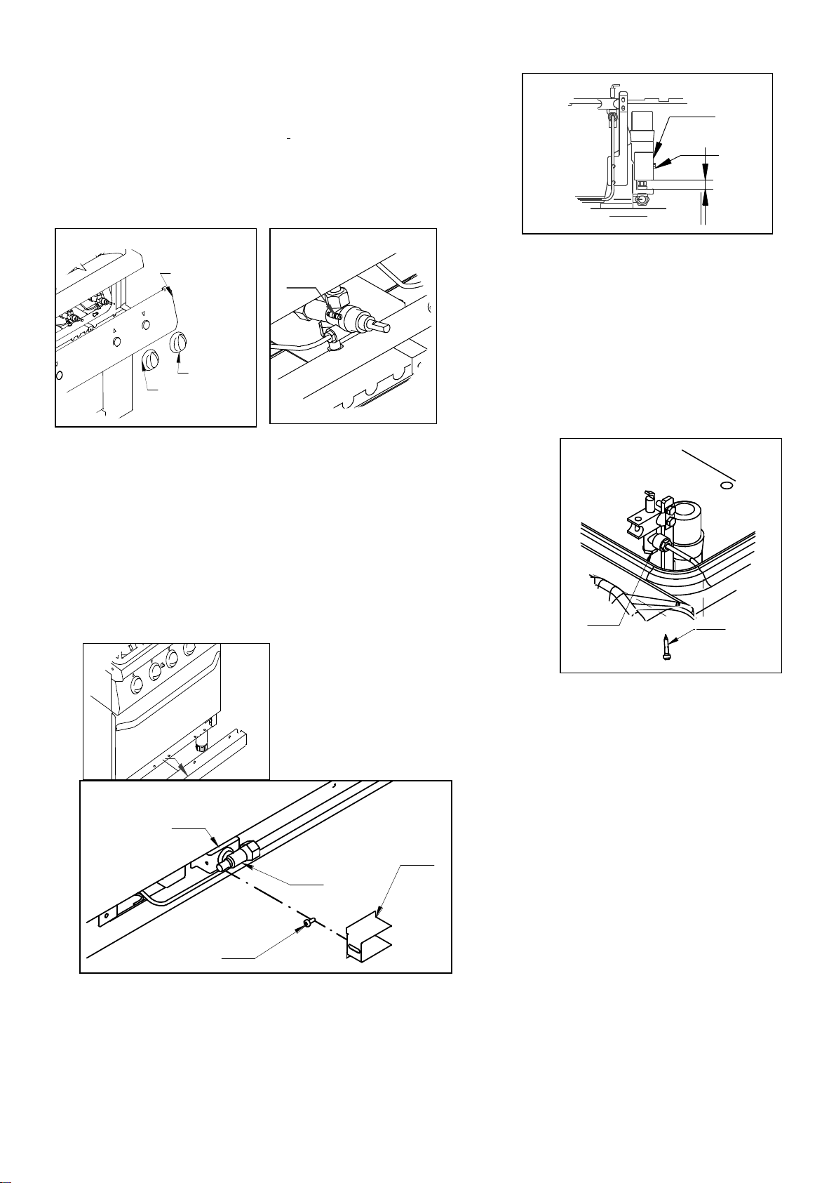
Checking gas tightness and pressure (fig. 23 – p. 11).
Before checking the gas pressure, it is necessary to check the tightness of the gas installation up to
the nozzle with a leak-finder spray to ensure that no damage has been done to the appliance during
transportation. Then, it is possible to check the inlet pressure, which can be carried out by means of
a pressure gauge, either a “U” gauge or an electronic gauge with a minimum definition of 0,1 mbar.
In order to measure the gas pressure, remove the screw (1) from the pressure outlet (2) and connect
it to the pressure gauge pipe. Open the appliance gas supply valve, check the pressure output, and
close the valve. Remove the pressure gauge pipe and screw the screws correctly into the pressure
outlet. The pressure valve has to be within the minimum and maximum values shown down below:
Pag. 82/118
Page 35

Type of gas
P
n
[mbar]
P
min
[mbar]
P
MAX
[mbar]
G20 (Methane)
20
17
25
G20 (Methane)*
25
20
30
G25 (Methane)
25
20
30
G25.1 (Methane)*
25
20
30
G30 (Butane) (3B/P)
28-30
25
35
G30 (Butane) (3+)
28-30
20
35
G30 (Butane) (3B/P)
50
42,5
57,5
G31 (Propane) (3B/P)
28-30
25
35
G31 (Propane) (3P, 3+)
37
25
45
G31 (Propane) (3B/P)
50
42,5
57,5
Power
Heat capacity
E =
(*These gases belong to II
category, which is used only in Hungary)
2HS3B/P
If the pressure measured is not within the limits shown in the table, find out the cause. After solving
the problem, check the pressure again.
Checking the appliance power
Normally it is sufficient to check that the nozzles installed are the right ones and that the burners
function properly. If desired, it is possible to check the power absorbed by using the “Volumetric
Method”, measuring the volume of gas output supplied to the appliance in time units with the aid of
a chronometer and a counter. The right comparison volume [E], measured in litres per hour (l/h) or
in litres per minute (l/min), can be obtained using the formula shown below dividing the nominal
and minimum outputs (power) shown in the table of burner features by the lowest heat capacity of
the gas type pre-arranged for the appliance. This value can be found in the norm tables or can be
provided by the local gas supply company.
The reading has to be done when the appliance is already in function.
Checking pilot burner
Check the flame of the pilot burner: it must be neither too short nor too high, but it has to lap the
thermocouple and have a sharp form; otherwise, check the nozzle size depending on the pilot
version, as specified in the following paragraphs.
Checking regulation of primary air
All the main burners are provided with primary air regulation. It is necessary to carry out the check
observing the values shown in the air regulation column of the burner features tables (pp. 64÷72). In
order to regulate the primary air, proceed as specified in the following paragraphs.
ATTENTION! All the parts protected and sealed by manufacturer can not be regulated by
the installer if not specifically indicated.
Pag. 83/118
Page 36

REGULATIONS AND SUBSTITUTIONS FOR USING A GAS
DIFFERENT FROM THE TYPE PROVIDED FOR
Functioning with a gas type different from the type provided for
In order to change to another gas type, it is necessary to substitute the nozzles of the main burners
and of the pilot burner, following the instructions in the following paragraphs. The nozzle type to be
installed can be found in tables 2÷11 (pp. 67÷76). The nozzles of the main burner, marked with
their diameter in hundredths, and the nozzles of the pilot burner, marked with a number, are to be
found in a transparent packet attached to the instruction booklet.
When the conversion is completed, check that the pipe joints are tight and that the ignition and
functioning of both the pilot and the main burner – both at minimum and maximum – are correct. It
may be advisable to check the output power.
Then, modify the technical sheet (figg. 15, p. 10) and place the sheet (provided as standard kit
equipment) referring to the new gas type in the G20 20mbar position.
Open rings
Replacing the burner nozzle (figg. 24, 25 – p. 11)
In order to replace the burner nozzle, remove the pan support grill (1), the gas ring (2), the burner
unit (3) and the drip pan (4). Then, unscrew the nozzle (5) from the nozzle holder (6), which is to be
found under the Venturi tube (7) with a spanner and replace it with the nozzle suitable for the gas
type to be used, as shown in tables 2÷11 (pp. 67÷76). Reassemble the nozzle, tightening it well, and
regulate the primary air, as indicated in the next paragraph. Finally, place back all the components
previously removed.
Regulating the burner primary air (fig. 26 – p. 12)
After replacing the burner nozzle, it is necessary to regulate the primary air. Therefore, unloose the
screw (8) that fixes the steel bushing (9); bring x value to the correct measurement with reference to
tables 2÷11 (pp. 67÷76); tighten up the screw (8) and check the accuracy of x value.
Repacing the by-pass (figg. 27, 28 – p. 12)
In order to replace the by-pass, it is necessary to remove the knobs (1) and the control panel (2).
Then, unscrew the by-pass (3) with a screwdriver and replace it with the by-pass suitable for the gas
type to be used, as shown in tables 2÷11 (pp. 67÷76). Reassemble the by-pass and tighten it well.
Finally, place back the control panel and the knobs.
Replacing the pilot burner nozzle (fig. 29 – p.12)
In order to replace the pilot burner nozzle, remove the pan support grill, the gas ring, the burner unit
and the drip pan, as shown in figure 24 (p. 11). Then, screw off the closure cap (1) with a spanner;
screw off the nozzle with a screwdriver (2) and replace it with the nozzle suitable for the gas type to
be used, as shown in tables 2÷11 (pp. 67÷76). Reassemble the nozzle and tighten it well.
Reassemble the closure cap (1) and tighten it well. Finally, place back all the components
previously removed.
Pag. 84/118
Page 37

Oven
Replacing the burner nozzle (figg. 30, 31 – p. 12)
In order to replace the burner nozzle, remove the front panel (1) under the oven door. Then,
unloosen the screw that secures the regulation of the primary air (3) and open them completely.
With the aid of another spanner unscrew the nozzle (5) placed in the nozzle holder (4) and replace it
with the nozzle suitable for the gas type to be used, as shown in tables 2÷11 (pp. 67÷76). Assemble
the new nozzle and tighten it well; then, regulate the primary air, as indicated in the next paragraph.
Finally, place back the front panel.
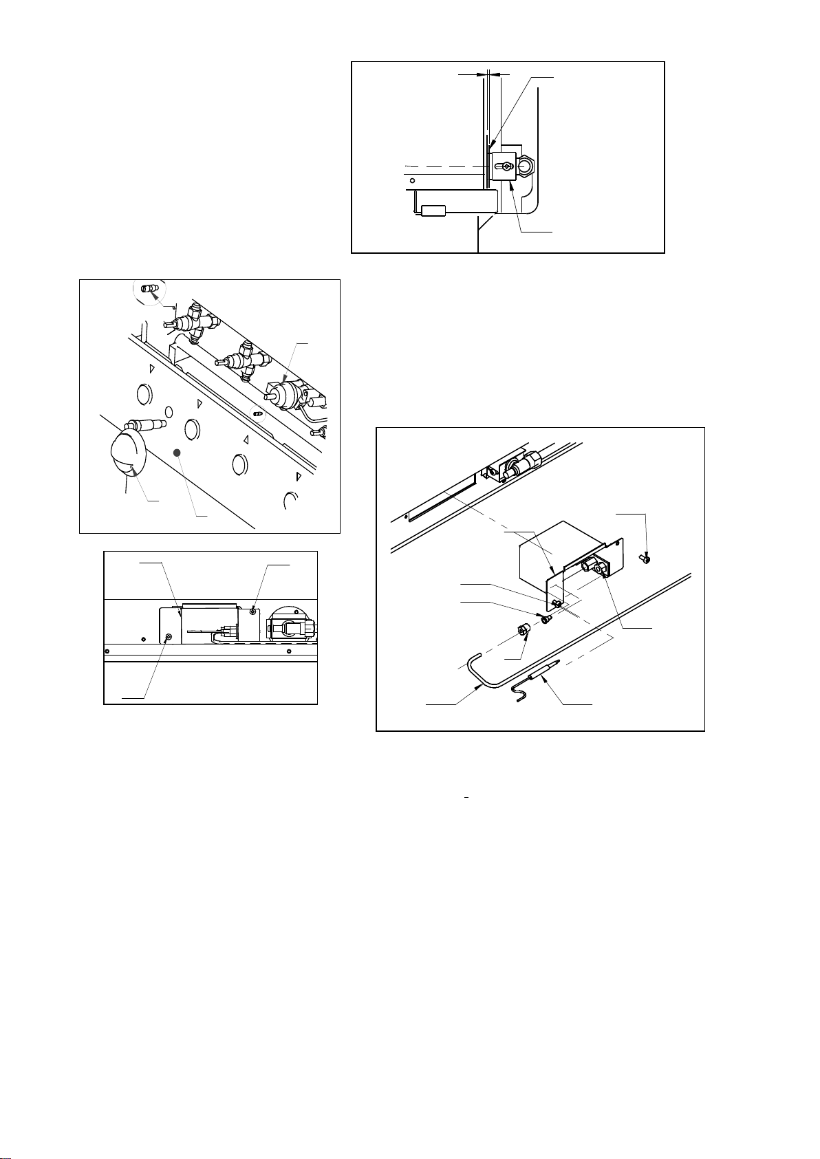
Regulating the burner primary air (fig. 32 – p. 13)
After replacing the burner nozzle, it is necessary to regulate the primary air. Therefore, unloose the
screw (2); bring the distance between the bushing (3) and the burner stirrup (6) to the correct
measurement (x value) with reference to tables 2÷11 (pp. 67÷76). Then, tighten up the screw and
check the accuracy of x value.
Replacing the by-pass (fig. 33 – p. 13) for oven with tap only
In order to replace the by-pass, it is necessary to remove the knobs (1) and the control panel (2).
Then, unscrew the by-pass (3), which is placed in the cock (4), with a screwdriver and replace it
with the by-pass suitable for the gas type to be used, as shown in tables 2÷11 (pp. 67÷76).
Reassemble the by-pass and tighten it well. Finally, place back the control panel and the knobs.
Replacing the pilot burner nozzle (fig. 34, 35 – p. 13)
In order to replace the burner nozzle, remove the front panel under the oven door. Then, unscrew
the screws (1) that fix the pilot support (2) with a screwdriver and remove them. Unscrew the nut
(3) that fixes the thermocouple (4) to the nozzle holder and slide it off; unscrew the fitting (5) that
fixes the gas supply pipe to the pilot (6) and take out the nozzle (7). Substitute the nozzle with one
suitable for the gas type to be used, as shown in tables 2÷11 (pp. 67÷76). Then, assemble the new
nozzle; place back the pipe and tighten the fitting fully. Put back the pilot support; fix it and place
back the front panel.
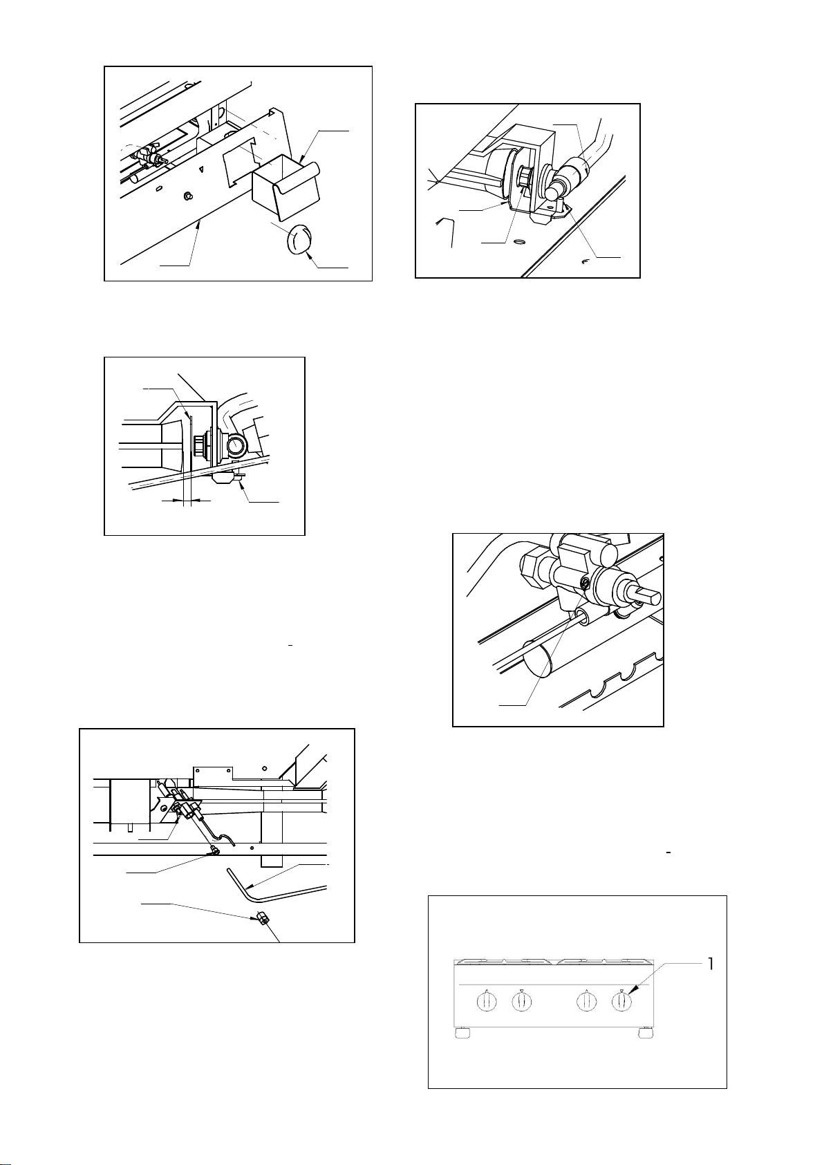
Maxi Oven
Replacing the burner nozzle (fig. 55 – p. 17)
In order to replace the burner nozzle, open the oven door and remove the oven bottom (1). Then,
remove the screws that secure the protection of the Venturi tube; unloose the screw that secures the
regulation of the primary air (3) and open it completely. With the aid of another spanner unscrew
the nozzle (5) placed in the nozzle holder (4) and replace it with the nozzle suitable for the gas type
to be used, as shown in tables 2÷11 (pp. 67÷76). Assemble the new nozzle and tighten it well; then,
regulate the primary air, as indicated in the next paragraph. Finally, place back the coverage of the
Venturi tube and the oven bottom.
Regulating the burner primary air (figg. 55, 56 – pp. 17, 18)
After replacing the burner nozzle, it is necessary to regulate the primary air. Therefore, unloose the
screw; bring the distance between the bushing and the burner stirrup to the correct measurement (x
value) with reference to tables 2÷11 (pp. 67÷76). Then, tighten up the screw and check the accuracy
of x value.
Pag. 85/118
Page 38

Replacing the pilot burner nozzle (figg. 57, 58, 59 – p. 18)
In order to replace the pilot burner nozzle, open the oven door and remove the cast iron bottom (1
and 2); unscrew the screws and remove the protection cover of the Venturi tube (3). Then, extract
the drilled protection (4); unscrew the nut (6) and extract the tube of the pilot burner (5). Remove
the biconic screw (7) and the pilot burner nozzle (8). Replace it with the nozzle suitable for the gas
type to be used. Put the new nozzle into the biconic screw and assemble it; put back the pipe of the
pilot burner and tighten the nut well. Put back the drilled protection, the stirrup and the cast iron
bottom.
All Hotplate
Replacing the burner nozzle (fig. 36, 37 – p. 14)
In order to replace the burner nozzle, remove the knob (1), the box (2), and the control panel (3).
Unloosen the screw (4) that secures the regulation of primary air (7) with a screwdriver and open it
completely. Unscrew the nozzle (6) from the nozzle holder (5) with a spanner and substitute it with
the nozzle suitable for the gas type to be used, as shown in tables 2÷11 (pp. 67÷76). Assemble the
new nozzle and tighten it well; then, regulate the primary, air as indicated in the next paragraph.
Finally, place back the panel and the knob.
Regulating the burner primary air (fig. 38 – p. 14)
After replacing the burner nozzle, it is necessary to regulate the primary air. Therefore, unloosen the
screw (1); bring the x value to the correct measurement with reference to tables 2÷11 (pp. 67÷76).
Then, tighten up the screw (1) and check the accuracy of x value.
Regulation at minimum (fig. 39 – p.14)
In order to function with liquid gas, the by-pass (1) has to be fully screwed and properly tightened.
On the other hand, while functioning with methane gas, the by pass (1) has to be regulated in the
following way: read the value of the minimum output in tables 2÷11 (pp. 67÷76) and convert it into
l/h using the "Volumetric method" previously described; at this stage the appliance can be started
up, following the instructions. Then, it is necessary to regulate the by-pass capacity by reading the
meter, turning it clockwise for reducing the flow and anti-clockwise for increasing it. After
regulating, fix the by-pass position with a drop of red paint, suitable for this use.
Replacing the pilot burner nozzle (fig. 40 – p.14)
In order to replace the pilot burner nozzle, remove the knob and the control panel as in figure 36.
Then, screw the fitting (1) that secures the gas supply pipe of the pilot (2) to the pilot support (4);
take out the nozzle (3). Substitute the nozzle with the nozzle suitable for the gas type to be used, as
shown in tables 2÷11 (pp. 67÷76). Then, assemble the new nozzle, place back the pipe and tighten
the fitting fully. Finally, place back the panel and knob.
Pag. 86/118
Page 39

INSTRUCTIONS FOR USE
Position (N°)
1 2 3 4 5 6 7 8 Temperature (°C)
140
160
180
205
235
260
280
300
Position (N°)
1 2 3 4 5 6 7
Temperature (°C)
60
100
140
180
220
260
300
Open rings (fig. 41 – p. 14)
In order to light the burners of the open rings, proceed in the following way:
- Turn the knob (1) from off position to the position ;
- Push down to the bottom;
- Light the pilot burner using a match or another lighter suitable for this use;
- Once lit, keep the knob pressed down until the thermocouple heats up, keeping the pilot lit;
- Light the main burner in the desired position, going from maximum to minimum .
In order to put out the main burner, the knob has to be turned to the right into the on position; as
for putting out also the pilot, turn the knob again into the off position .
Oven and maxi oven (fig. 42 – p. 15)
In order to light the oven burner, proceed in the following way:
- Open the oven door and turn the knob (1) from the off position into the position ;
- Press down the button;
- Push the button of the piezoelectric lighter (2) to light the pilot burner;
- Keep the knob pressed down until the thermocouple heats up, keeping the pilot lit; this can be
checked through the hole in the bottom of the oven;
- Light the main burner, positioning the knob in one of the possible positions. Choose the
position most suited to the desired type of cooking, considering that every position corresponds
indicatively to the temperatures shown below:
Oven with tap
Oven with valve
In order to put out the main burner, the knob has to be turned to the right into the on position ; as
for putting out also the pilot, turn the knob again into the off position. .
All hotplate (fig. 43 – p. 15)
In order to light the burner of the all hotplate, proceed in the following way:
- Turn the knob (1) from the off position into the position ;
- Push down to the bottom;
- Press the button of the piezoelectric lighter (2) to light the pilot burner;
- Keep the knob pressed down until the thermocouple heats uo, keeping the pilot lit;
- Light the main burner in the desired, going from maximum to minimum .
In order to put out the main burner, the knob has to be turned to the right into the position ;
as for putting out also the pilot, turn the knob again, into the off position .
Pag. 87/118
Page 40

Electric round and square hotplates (fig. 44 – p. 15)
Position [N°]
Use
0
Hotplate off
1
Maintaining temperature
2
Cooking small quantities
3
Cooking large quantities
4
Cooking at medium temperature
5
Cooking at high temperature
6
Starting cooking
Position no.
Use
Plate off
Fan and total heating
Total heating
Fan and baking from the bottom
Baking from the bottom
Fan and gratin
Cooking au gratin
In order to turn on a hotplate on the electric cookers, proceed in the following way:
- Turn the knob (1) into the desired position; the green light comes on to show that the hotplate is
on.
It is advisable to turn on the hotplate at the maximum temperature in order to reach the desired
temperature immediately. Leave it in this position for a few minutes; then, turn the knob into the
desired position.
In order to turn off the hotplate turn the knob into the 0 position.
ATTENTION! Use the appliance only under observation. Never leave the hotplate
functioning empty. The recipient used has to have an adequate diameter for the hotplate,
preferably no smaller and with a flat bottom.
Ventilated electric oven (fig. 45 – p. 15)
Before turning on the electric oven, it is necessary to select the desidered type of cooking in the
following way:
- Turn the knob (1) into the desired position;
Pag. 88/118
Page 41

- Regulate the cooking temperature desired with the thermostat (2), the two lights come on. The
Problem
Possible solution
The pilot burner does not light on
- Check that gas inlet pressure is the same as that shown in
table at page 82
- Check that the nozzle of pilot burner is not blocked
- Check that the igniter plug is well fixed and connected
- Check that the igniter plug is intact
- Check that the igniter cable is intact
- Check that the piezoelectric igniter is intact and
functions correctly
- Check the gas valve
green light stays on to indicate the presence of electrical tension, while the orange one goes off
as soon as the oven reaches the temperature.
- In order to turn off the oven, turn one of the two knobs back into position 0.
Electric oven (fig. 51 – p. 16)
Before turning on the electric oven, it is necessary to select the desired type of cooking in the
following way:
- Turn the knob (1) into the desired position: full heating , cooking from the bottom , au
gratin ;
- Regulate the desired cooking temperature with the thermostat (2), the two lights come on. The
green light stays on to indicate the presence of electrical tension, while the orange one goes off
as soon as the oven reaches the temperature.
- In order to turn off the oven, turn one of the two knobs back into position 0.
Glass ceramic electric cooker (fig. 60 –page 18)
To switch on a plate proceed as follows:
- Rotate the knob (1) in the desired position; the lamp (2) switches on to indicate that the chosen
plate is on (the chosen zone will become red on the glass ceramic surface). This knob (fig.61
pag.18) is linked to the power regulator, by rotating it the machine switches on. In relation to
the position the plate work in a cycle of switching on and off in order to maintain a constant
radiance temperature. By choosing a bigger area marked on the knob the switching on time
becomes higher than the off one. Between the limit of the maximum area and the indicator the
plate works always at the maximum supplied power.
- In order to avoid uncontrolled and dangerous rise up of the temperature, the machine is
equipped with an automatic safety thermostat which intervene to a fixed temperature.
Abnormal functioning
If for any reason, the appliance does not start or stops working during use, check that the energy
supply and the control knobs are set correctly; if all is regular, call customer service.
Some problems and possible solutions
Pag. 89/118
Page 42

The pilot burner lights off after
loosening the igniter knob
- Check that gas inlet pressure is the same as that shown in
table at page 82
- Check that the flame of the pilot burner laps the
thermocouple; if this is not the case, adjust the pilot
burner through the regulating screw on the valve
- Press the gas knob in its correct position
- Change the thermocouple
- Check if the valve magnetic group is rusted
- Check the gas valve
The pilot burner stays on but the main
burner does not light on
- Check that gas inlet pressure is the same as that shown in
table at page 82
- Check that the gas nozzles are not blocked
- Check that the burner holes are not blocked
- Check that the gas pipe is not blocked
- Check that the nozzles installed are in accordance to
tables 2÷11
- Check the gas valve
Slow and/or inadequate heating
- Check that gas inlet pressure is the same as that shown in
table at page 82
- Check that the nozzles installed are in accordance to
tables 2÷11
- Check the gas valve
No heat
- Check the power supply
- Check the condition of the heating element
- Check the thermostat
No indicator light
- Check the power supply
- Check the light bulb
Slow and/or insufficient heat
- Check the setting of the thermostat
- Check the condition of the heating elements
- Check the quantity of food to be cooked
CARE AND MAINTENANCE OF THE APPLIANCE
Cleaning
ATTENTION! Before doing any cleaning, make sure that the appliance is disconnected from
the electric mains and that the gas cutoff valve is closed. During cleaning operations, avoid
using direct or high pressure sprays of water on the appliance. Cleaning must be done when
the appliance is cold.
The parts in steel can be cleaned with warm water and neutral detergent, using a cloth; the detergent
must be suitable for cleaning stainless steel and must not contain abrasive or corrosive substances.
Do not use common steel wool or anything similar which, depositing iron particles, could cause rust
from it. It is also better to avoid using sandpaper or emery paper. Only in the event of encrusted
dirt, pumice stone in powder may be used but an abrasive synthetic sponge or stainless steel wool
would be preferable, to be used in the direction of the grain. After washing, dry with a soft cloth.
For cleaning open rings, remove the pan support grills, the drip pan, the gas ring, the burner unit
and clean with warm water, neutral detergent and an appropriate utensil, then rinse and dry well.
Finally, put back all the components, being careful to fit them properly into place. To clean the
Pag. 90/118
Page 43

oven, remove the wire grill, the bottom, the top diffusor (in the electric oven), the grill holder and
Type of dirty
Suitable material of cleaning.
Light dirty without any dry residue
Wet tissue.
Spots of grease (sauces, soups, oil)
Clean with a non-abrasive detergent
Sticky dirty
Non-abrasive detergent and clean with a wet tissue
Calcar and water residues
Clean off with vinegar, creamy detergent and clean
carefully with a wet tissue.
Sugar, food, plastic or aluminium crusts.
Scrape on the spot with a scraper (razor blade), clean
with a creamy detergent and than again with a wet
cloth. If the area should cool down with this kind of
dirty the glass ceramic could deteriorate.
clean them with warm water, neutral detergent and an appropriate utensil, rinse and dry well.
Finally, put back all the components, being careful to fit them properly into place.
The cleaning mode of the glass ceramic is the same of the glass. Do not use any corrosive detergent,
as oven sprays, iron wool or cleaning dust.
Before the cleaning, the glass ceramic surface must be left cooling.
Any detergent residue must be clean off from the cooking zone with a wet tissue since with the heat
they could give a corrosive reaction.
Suggestions related to the cleaning of the glass ceramic:
ATTENTION: let the cooking surface cooling before cleaning
If the appliance is out of use for a long time, it is advisable to turn off the gas tap. Then disconnect
the main electricity supply and wipe all stainless steel surfaces with a cloth soaked in vaseline oil in
order to give it a protective film and air the rooms now and again.
Maintenance
ATTENTION! Before doing any kind of maintenance or repairs, make sure that the
appliance is disconnected from the electric mains and that the gas cutoff valve is closed.
The following maintenance operations must be carried out at least once a year by specialized
personnel. It is advisable to have a maintenance contract.
Check for correct functioning of all control and safety devices;
Check for correct ignition of burners and proper functioning at minimum;
Check the thightness of the gas pipes;
Check the condition of the power cable;
Clean the evacuation pipes of type "B" appliances, following the prescriptions in force in the
country of installation;
The gas tap should be lubricated but this is a difficult operation and not very reliable; therefore
it is advisable to substitute it;
Pag. 91/118
Page 44

SUBSTITUTING COMPONENTS
ATTENTION! Before carrying out any substitutions, make sure that the appliance is
disconnected from the electric mains and that the gas cut-off valve is closed.
Safety cock in open rings and all hotplate
In order to replace the cock, remove the knobs and the control panel; then, unscrew in sequence the
pipe union of the piping which goes to the burner, the pipe union of the piping of the pilot burner,
the thermocouple and finally, the pipe union of the ramp. Replace the cock.
Safety thermostat of the oven and maxi oven
In order to replace the oven thermostat, remove the knobs and the control panel of the oven; then,
unscrew in sequence the pipe union of the piping which goes to the burner, the pipe union of the
piping of the pilot burner, the thermocouple and finally, the pipe union of the ramp. Replace the
thermostat.
Thermocouple of open rings
In order to replace the thermocouple of the open-flame gas rings, remove the knobs and the control
panel, the pan support grill, the gas ring, the burner unit and the drip pan. Unscrew the fitting of the
thermocouple on the cock, take out the pilot unit and replace the component.
Oven thermocouple and maxi oven
In order to replace the oven thermocouple, remove the knobs and the oven control panel. Then,
unscrew the fitting of the thermocouple on the cock and the one on the pilot uni. Replace the
component.
All hotplate thermocouple
In order to substitute the thermocouple of the all hotplate, remove the knobs and take off the control
panel. Unscrew the fitting of the thermocouple on the cock and the one on the pilot unit; then,
replace the component.
Fan of the ventilated electric oven (fig. 47, p. 16)
In order to replace the fan of the ventilated electric oven, unscrew the fixing screws (1) of the
protection shield (2); remove the protection shield; unscrew the blocking nut (3) of the fan (4) and
extract it. Then replace it. In order to assemble the fan proceed in reverse.
Motor of the ventilated electric oven (fig. 48, p. 16)
In order to replace the motor of the ventilated electric oven, proceed as described in the preceding
paragraph: remove the fan and the appliance back panel, so to reach the oven back side. Disconnect
the electric cables; unscrew the fixing screws (5) that fasten the motor to its support and remove the
motor (4) from the support.
Electric components of the ventilated electric oven (fig. 49, p. 16)
In order to replace the selector (4) and the thermostat (5) of the ventilated electric oven, unscrew the
fixing screws (1 and 2) of the control board (3); remove the control board; disconnect the electric
cables of the component and replace the component. Then, connect the electric cables following the
instructions of the wiring diagram.
Ventilated electric oven elements (fig. 50, p. 16)
In order to replace the heating elements of the ventilated oven, extract the wire grill, the bottom (1),
the top diffusor and the grill holders. Then, unscrew the fixing screws (2) of the element to be
Pag. 92/118
Page 45

substituted (3); remove the heating element from the support from the other side; remove it,
including the wiring, and disconnect it.
Electric components of the electric oven (fig. 53, p. 17)
In order to replace the selector (4) and the thermostat (3) of the electric oven, unscrew the fixing
screws of the control board (1) and of the protection (2); move them; remove them. Disconnect the
electric cables of the component and replace it. Then, connect the electric cables following the
instructions of the wiring diagram.
Electric oven elements (fig. 54, p. 17)
In order to replace the heating elements of the oven, extract the wire grill, the bottom (1), the top
diffusor and the grill holders. Then, unscrew the fixing screws (2) of the element to be substituted
(3); remove the heating element from the support from the other side; remove it, including the
wiring, and disconnect it.
Replacing of the heating element of the glass ceramic electric cooker
In order to replace the heating element, unscrew the control panel, unloose the fixing screws of the
frame and take it off, unloose the connection wires of the heating element paying attention to hold
upside the open part of the heating element during the replacing.
Power regulator of the glass ceramic plate.
In order to replace the power regulator of the glass ceramic plate, unscrew the fixing screws of the
instrument panel, remove it, than unplug the electric wires and replace the component. Once
replaced it, plug the wires again referring to the electrical scheme.
Information for electrical and electronic devices used in EU countries
The devices, which are marked with the following symbol , may not be disposed of with
household refuse in accordance with the EU directive.
To eliminate your used device, please use the country-specific differentiated collection systems
available or contact your retailer, when you buy an equivalent device.
By actively using the offered collection systems, you make your contribution to the reuse, recycling
and utilisation of electrical or electronic devices, protecting the atmosphere and the health.
Abusive product disposal by the user is punishable by law with administrative sanctions according
to the Art. 50 and following from the D.Lgs. 22/1997.
WHEN SUBSTITUTING ANY COMPONENTS ONLY ORIGINAL SPARE PARTS
SUPPLIED BY THE MANUFACTURER HAVE TO BE USED. THE OPERATION HAS TO
BE CARRIED OUT BY AUTHORIZED PERSONNEL.
ATTENTION! In the event that components of the gas installation have been substituted, it is
necessary to check for tightness and the correct functioning of the various parts.
THE MANUFACTURER RESERVES THE RIGHT TO MODIFY WITHOUT NOTICE
THE FEATURES OF THE APPLIANCES DESCRIBED IN THIS MANUAL.
Pag. 93/118
 Loading...