

Page 1
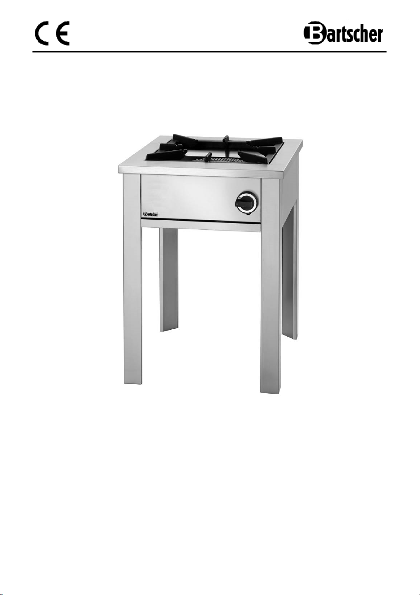
1312AQ937
Original
-
Gebrauchsanleitung
280PRO
1050603
V1/0217
Page 2

GB/UK
ENGLISH
Table of contents
1.Safety ........................................................................................................................ 26
1.1 Key to symbols .................................................................................................... 26
1.2 Safety instructions ............................................................................................... 27
1.3 Proper use ........................................................................................................... 30
2. General information ................................................................................................ 31
2.1 Liability and Warrantees ...................................................................................... 31
2.2 Copyright protection ............................................................................................ 31
2.3 Declaration of conformity ..................................................................................... 31
3. Transport, packaging and storage......................................................................... 32
3.1 Delivery check ..................................................................................................... 32
3.2 Packaging ........................................................................................................... 32
3.3 Storage ................................................................................................................ 32
4. Technical data ......................................................................................................... 33
4.1 Technical specification ........................................................................................ 33
4.2 Overview of parts ................................................................................................ 36
5. Installation and operation ....................................................................................... 39
5.1 Instructions for the Installer ................................................................................ 39
5.1.1 Safety instructions ..................................................................................... 39
5.1.2 Preset ........................................................................................................ 40
5.1.3 Gas connection.......................................................................................... 41
5.1.4 Output control ............................................................................................ 41
5.1.5 Adjustment to another gas type / required settings ................................... 42
5.2 User instructions ................................................................................................ 44
5.2.1 Important tips ............................................................................................. 44
5.2.2 Device switch on/off ................................................................................... 45
6. Cleaning and maintenance ..................................................................................... 46
7. Possible Malfunctions ............................................................................................ 47
8. Waste disposal ........................................................................................................ 48
Bartscher GmbH
Franz-Kleine-Str. 28
D-33154 Salzkotten phone: +49 (0) 5258 971-0
Germany fax: +49 (0) 5258 971-120
- 25 -
Page 3
Read these instructions before using and keep
them available at all times!
This instruction manual contains information about the installation, operation and
maintenance of the device and should be consulted as an important source of
information and reference guide.
Awareness of the safety instructions and instructions for use in this manual will ensure
the safe and correct use of the device.
In addition to the information given here, you should comply with any local Health and
safety Controls and generally applicable safety regulations.
The instruction manual forms part of the product and should be kept near the device
and easily accessible for anyone carrying out the installation, servicing, maintenance or
cleaning.
1.Safety
This device is designed in accordance with the presently applicable technological
standards. However, the device can pose a danger if handled improperly and
inappropriately.
All persons using the device must follow the recommendations and instructions
in this instruction manual.
1.1 Key to symbols
In this manual, symbols are used to highlight important safety instructions and any
advice relating to the device. The instructions should be followed very carefully to avoid
any risk of accident, personal injury or material damage.
DANGER!
This symbol highlights hazards which could lead to injury.
WARNING!
This symbol highlights dangerous situations which could lead to injury or death.
- 26 -
Page 4
HOT SURFACE!
This symbol is a warning that the device surface is hot when in use.
Ignoring this warning may result in burns!
CAUTION!
This symbol highlights dangerous situations which could lead to light
injuries, or damage, malfunction, and/or destruction of the device.
NOTE!
This symbol highlights recommendations and information aimed for effective
and trouble-free device operation.
1.2 Safety instructions
• The device is not intended for use by individuals (including
children) with physical or mental disabilities, insufficient
experience, and/or insufficient knowledge unless such persons
are under the care of a person responsible for their safety or
have received instructions regarding appropriate use of the
device.
• Do not leave children unattended to make sure that they
neither play with the device nor try to switch it on.
• Prevent access of children to the package materials like plastic
bags and foamed polystyrene elements. Suffocation hazard!
• Never leave the device unattended when in use.
- 27 -
Page 5

• Do not use the device in enclosed areas.
• Install the device in a well-ventilated room, if possible under the
exhaust hood, in order to ensure extraction of all gases created
during combustion. For proper combustion, the air inflow cannot
be lower than 2 m3/h per kW of rated power of the device (see:
rating plate attached to the device).
• The device may be operated only when it is in good working
order and is safe to use. In case of any malfunction, disconnect
the device from the gas supply (close the gas shut-off valve) and
notify the technical service.
• Never try to disassemble the device or repair it. Maintenance
and repair work may be performed only by the qualified gas
installer, while observing the applicable regulations and using
original spare parts and accessories.
• Do not use any accessory or spare parts that have not been
recommended by the manufacturer. These can be dangerous
for the user or lead to damages of the device or personal injury,
and further, the warranty expires.
• To prevent hazards and to ensure optimum efficiency, no
modifications or alterations to the device that are not explicitly
approved by the manufacturer may be undertaken.
• Before cleaning or maintenance work, as well as a longer
interruption in the operation of the device, disconnect the device
form the gas supply (close the gas shut-off valve).
- 28 -
Page 6
WARNING Risk of burns!
To avoid the hazard results please follow the safety instructions
below.
• During the ignition process, never lean over the cooking area.
High flames from this area my lead to severe burns.
• Never touch the hot surface of the gas burner during its
operation, and immediately afterwards. External elements may
be very hot. Keep small children away from the device. Before
cleaning or moving the device, leave it to cool off. Use dish
cloths or protective gloves.
WARNING Fire and explosion hazard!
To avoid the hazard results please follow the safety instructions
below.
• To avoid the fire hazard and the damages to the device never
place the kitchen utensils, towels, paper, etc. on the stock-pot
oven.
• Never use the device near flammable materials, such as
alcohol, spirits, or petrol. High temperature may cause their
evaporation and due to contact with the ignition sources the
deflagration may occur, thus resulting in injuries and damages.
• Never leave the device unattended when fats and oils are
cooked, as they may cause fire.
• Never clean the device with inflammable liquids. Vapors may
cause fire or explosion.
• In case of fire, never extinguish the flame with water, close the
gas shut-off valve and smother the flame with a cover or fire
blanket.
- 29 -
Page 7

1.3 Proper use
CAUTION!
The device has been designed and built for commercial use and should
be operated only by qualified personnel in kitchen facilities.
The operational safety of the device is assured only in case of proper use, according
to the operation manual.
All technical activities like installation and maintenance must be performed by the
qualified service personnel only.
Gas stock-pot stove is intended only for cooking and heating food using appropriate
utensils.
CAUTION!
Any use going beyond the intended purpose and/or any different use of the
device is forbidden and is not considered as conventional.
Any claims against the manufacturer or his authorized representative as a
consequence of experiencing damages resulting from unconventional use
are impossible.
The operator is liable for all damages resulting from inappropriate use.
- 30 -
Page 8

2. General information
2.1 Liability and Warrantees
All the information and instructions in this manual take into account standard safety
regulations, current levels of technical engineering as well as the expertise and
experience we have developed over the years.
The instruction manual was translated with all due care and attention. However, we do
not accept liability for any translation errors. The German version of this instruction
manual is definitive.
If the delivery consists of a special model, the actual scope of delivery may differ from
the descriptions and illustrations in this manual. This is also the case for special orders
or when the device has been modified in line with new technology.
CAUTION!
Read this manual carefully and thoroughly before any operation
of the device, and especially before turning it on!
Manufacturer is not liable for any damages or faults caused by:
- violation of advice concerning operation and cleaning;
- use other than designed;
- alterations made by user;
- use of inadequate spare parts.
We reserve the right to make technical changes for purposes of developing and improving
the useful properties.
2.2 Copyright protection
The instruction manual including any texts, drawings, images or other illustrations is
copyright. No part of this publication may be reproduced, transmitted or used in any
form or by any means without permission in writing from the manufacturer. Any person
who commits any unauthorized act in relation to this publication shall be liable to claims
for damages. All rights reserved.
NOTE!
The contents, texts, drawings, pictures and any other illustrations are
copyright and subject to other protection rights. Any person unlawfully
using this publication is liable to criminal prosecution.
2.3 Declaration of conformity
The device complies with the current standards and directives of the EU.
We certify this in the EC declaration of conformity. If required we will be
glad to send you the according declaration of conformity.
- 31 -
Page 9
3. Transport, packaging and storage
3.1 Delivery check
Please check the delivery upon completeness and transport damage immediately
after receipt. In case of visible damage do not accept or accept the delivery with
reservation only.
Note the extent of damage on the carrier’s bill of delivery. Trigger off the complaint.
Hidden damages should be reclaimed immediately after notice, as claims for damages
can only be asserted within the effective period for complaints.
3.2 Packaging
Please do not throw away the covering carton of your device as it might be useful for
storage purposes, when moving or, in case of damages, when the device must be sent
back to a repair center. The outer and inner packing material should be removed
completely from the device before installation.
NOTE!
If you liked to dispose the packing, consider the regulations applicable in
your country. Supply re-usable packing materials to the recycling.
Please inspect the device upon completeness. In case any part is missing please
contact our customer service center immediately.
3.3 Storage
Keep the package closed until installation and under consideration of the outside
indicated positioning- and storage markings.
Packages should be stored under consideration of the following:
- do not store outdoors,
- keep it dry and dust-free,
- do not expose it to aggressive media,
- do not expose it to direct sunlight,
- avoid mechanical shocks and vibration,
- in case of longer storage (> 3 months) make sure you check the state
of the packaging and the parts regularly, if required refresh or renew;
- disconnect the device from the gas cylinder before storage.
- 32 -
Page 10
4. Technical data
4.1 Technical specification
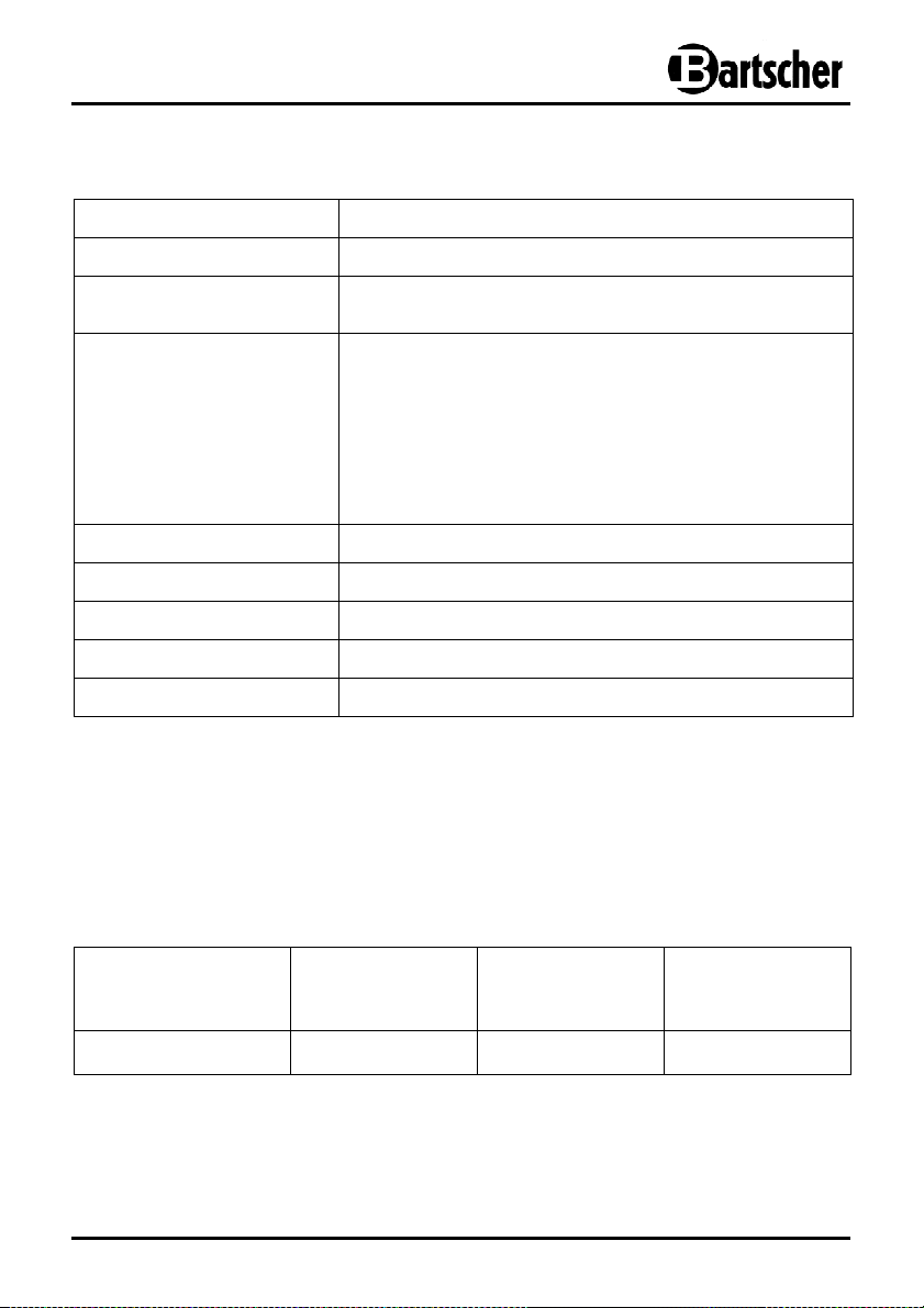
Name Gas stock-pot stove 280PRO
Art. no.:
Material:
Design:
Power: 12.5 kW
Dimensions: W 680 x D 590 x H 820 mm
Pot / pan diameter: Minimum 280 mm
Carrying capacity: 70 kg
Weight: 31.0 kg
We reserve the right to implement the technical modifications!
1050603
Nickel-chrome steel 18/10
Cast iron support
Type of gas: Propane,
Natural gas nozzles H and L are included
Gas burner: nozzle burner
Type of ignition: manual ignition
Pilot flame
Ignition safeguard
Fat drip tray under the burner
*** All stock-pot stoves come without connection fittings,
a gas pressure regulator with max. 50 mbar is required for industrial use, as well
as a safety valve in case of loss of pressure.
Table 1: Gas inlet pressure
Primary
combustion air
Model / Code-No.:
Nominal heat
output
(kW) (kg/h) (m3/h)
Liquid gas
consumption
FOGV50 / 1050603
12.5 0.98
2 m3/h per kW
- 33 -
Page 11

Table 2: Features of Burners and nozzles
Category II2ELL3B/P Type A Design
Burner
Nominal heat output (kW) 12.5
Gas consumption
- Natural gas LL (m3/h)
- Natural gas E
- Liquid gas (kg/h)
Natural gas LL
Pilot flame
Max
Min.
Natural gas E
Nozzles
(1/100 mm)
Pilot flame
Max.
Min.
Liquid gas
Pilot flame
Max
Min.
Distance “H” of
the primary air
(mm)
Natural gas LL
Natural gas E
Liquid gas
1.54
1.32
0.98
35
290
R
35
260
R
20
160
110
1.5
1.5
2.5
- 34 -
Page 12
CAUTION!
The device operates properly only when the pressure in the gas distribution
grid is between the values provided in the table below for various gas types.
Application of gas categories in different countries
Country of destination Gas supply pressure Category
FR-BE
IT-ES-PT-IE-GB-GR-CZ-SK
FI-SI-NO-HR-TR-LT-LV-EE-
RO-BG
AT-CH
DE
NL
IS
CY-MT
HU-CY-MT
PL-LU
DK
SE
20/25; 28-30/37 mbar
20; 28-30/37 mbar
20; 30 mbar
20; 50 mbar
20; 50 mbar
25; 30 mbar
30 mbar
28-30/37 mbar
30 mbar
20 mbar
8; 20; 30 mbar
8; 20; 30 mbar
II2E+3+
II2H3+
II2H3B/P
II2H3B/P
II2ELL3B/P
II2L3B/P
I3B/P
I3+
I3B/P
I2E
III1a2H3B/P
III1ab2H3B/P
CAUTION!
In case of deviation from the above mentioned values, there is no guarantee of proper
functioning and correct activation of the device. Ask the gas installer to check the gas
supply (inspect the gas installation, valves and possibly pressure regulators), if
necessary consult the gas supplier.
- 35 -
Page 13
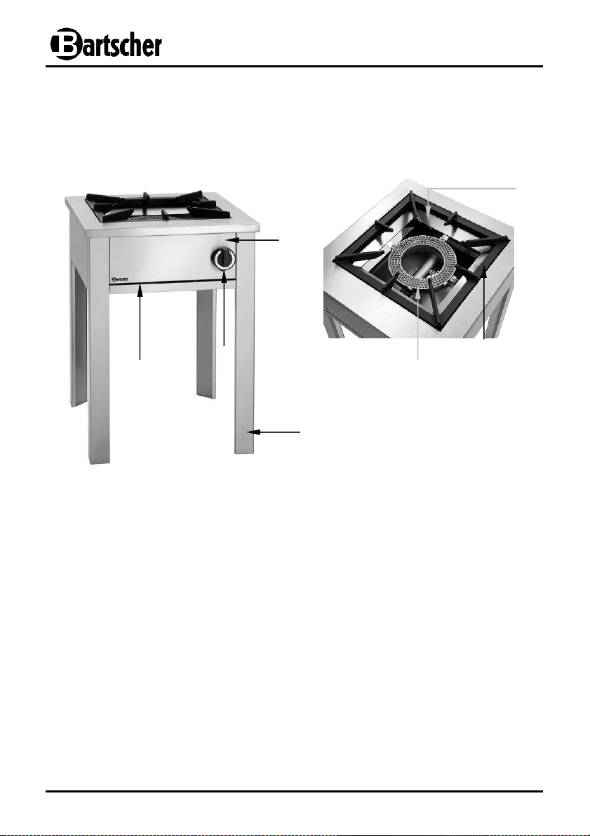
Fig. 1
Fig
. 2
4.2 Overview of parts
Figures
5
1
6
4
3
7
2
Housing
1
Feet
2
Burner knob
3
Removable fat drip drawer
4
Tin holder
5
Cast iron ribbed support
6
Nozzle burner
7
- 36 -
Page 14
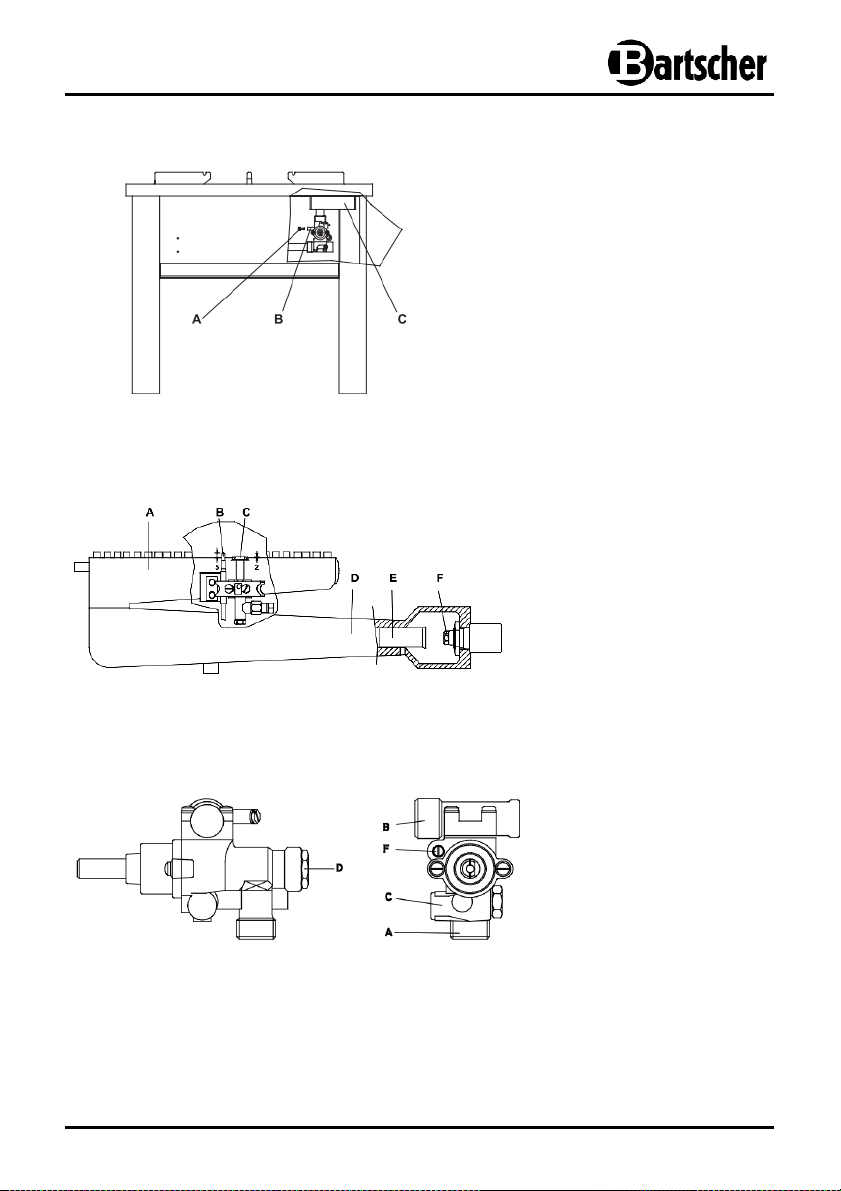
C
-
D
-
E
-
Fig. 3
Fig. 4
Fig. 5
A -
Gas manifold
B -
Pressure control connector
C -
Sealing screw
A -
Burner body
B -
Thermocouple
C -
Pilot flame
D -
Venturi tube
E -
Air regulating bush
F -
Nozzle
A -
Gas inlet connection
B -
Gas outlet connection
Gas outlet connection
for pilot flame
Thermocouple
connection
Low flame adjustment
screw
- 37 -
Page 15
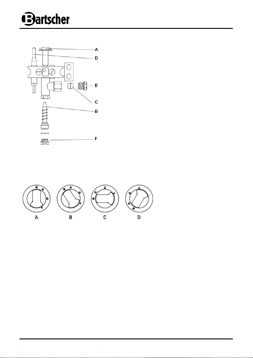
Fig. 6
Fig. 7
A -
Upper part of the burner
B -
Nozzle
C -
Double taper ring
D -
Thermocouple
E -
Gas tube screw
F -
Sealing screw
A -
OFF position
B -
Pilot flame position
C -
Max. position
D -
Min. position
- 38 -
Page 16
5. Installation and operation
5.1 Instructions for the Installer
CAUTION!
Any installation, connection and maintenance work must be performed only
by the qualified, possibly authorized personnel, who meets the following
requirements:
a) approved by our company:
b) certificate of the local gas supplier.
Apart from these requirements, the following regulations must be observed:
Furthermore, relevant provisions of the Building Code and Commercial Law,
HSE and VDE regulations must be observed.
5.1.1 Safety instructions
1. Make sure that the gas supply at the installation site is sufficient for the operation of
2. Before the test run of the device, place it in a well-ventilated room and remove any
3. Before starting the device, inspect the installation for leakages using soapsuds (leak
4. Before cleaning or maintenance of the device, disconnect the gas supply from the
1) DVGW TRGI (Technical regulations regarding gas installations);
2) TRF (Technical regulations regarding the liquid gas);
3) DVGW G 631 (Installation of commercial kitchen appliances of gas
fuel combustion).
CAUTION!
Incorrect installation, maintenance, cleaning or changes introduced to the
device may lead to severe injuries or death or damage the device.
the device.
inflammable materials from its surroundings.
detection spray). Cover the pipe joints and connections with soapsuds. Leaks will
become visible through air bubbles forming on pipe joints and connections. As an
alternative, you may observe the gas meter. No movement on the gas meter indicates
that there is no gas leakage. Never use open flame to test gas pipes for leaks!
device at the safe place (close the gas shut-off valve!).
- 39 -
Page 17

5.1.2 Preset
• Never place the device in toxic or explosive environment.
• Never place the device near flammable materials, such as petrol, fat, clothes,
liquid gas, paper etc.
• Never place the device in wet room / environment, such as e.g. rain or near
leaking water etc.
• Only authorized personnel may carry out the installation. The device must be
installed in compliance with the safety standards for gas supplied devices,
applicable in a given country.
• Make sure that there are no objects around or under the gas stock-pot stove which
may reduce the volume of the air required for combustion.
• The room in which the device is installed, must have the volume of air required for
gas combustion according to the applicable regulations. For the appropriate
combustion, the required air supply cannot be lower than 2 m3/h per kW of the
rated output of the device (see the rating plate on the device).
• Remove any flammable materials from the vicinity of the device.
• Never place the device directly against walls, low walls, furniture or other objects
which are made of flammable material. Keep a distance of at least 20 cm at the
sides and at the rear from walls and other objects. Take into account the applicable
fire protection regulations.
• If keeping the above mentioned distance is impossible, apply appropriate safety
measures (e.g. heat-resistant foil), which will ensure keeping the wall’s temperature
within the safe range
• Place the device on an even, stable, dry and waterproof and heat-resistant surface
near the gas connection.
• Before the first use, remove the protective foil from the device. Remove any glue
residues from the foil with an appropriate solvent.
CAUTION!
Never remove the rating plate or any warning signs from the device.
- 40 -
Page 18

5.1.3 Gas connection
• Before the installation of the device and its connection to the gas supply, carefully
inspect the elements of gas installation which should comply with the provisions of
the Building Code.
• Check the pipes diameters in order to ensure sufficient supply to all the gas-heated
devices. To avoid excessive pressure drop, install the device while maintaining
similar conditions.
• Connection to the gas distribution grid should be made of metallic, hard or flexible
material with the use of tubes of proportional diameter. Insert a gasket appropriate
for gas products.
• Make sure that flexible tubes do not pass on or near hot surfaces, are not subject to
strain or pressure and have no contact with sharp edges or other objects which
might damage the tube.
• A certified gas shut-off valve must be installed in an accessible place between the
gas distribution grid and the device, to allow for cutting off the gas supply at any
moment, if necessary.
• Check if the gas cylinder (if attached) is properly set and secured and whether it
stands in a dry place.
• Before the installation, make sure that the device is set for gas and pressure
available at the installation site (see rating plate on the device and packaging). If the
factory settings do not match, the device must be switched to another gas type
(Chapter 5.1.5 „Switching the device to another gas type / required settings”).
• After the installation of the gas stock-pot stove, a leak test of all gas pipes should be
performed with the use of water with soap or leak detection spray.
5.1.4 Output control
Checking nominal heat output
• During the initial installation, the gas installer must check the nominal heat load of
the device, as well as carry out maintenance and if necessary – switch the device to
another gas type.
• Never try to increase the output or nominal heat of the device provided by the
manufacturer.
• Control the nominal heat load with the use of gas meter and stopwatch. Measure
precisely the volume of flowing gas per unit of time, consumed by the device at the
maximum output.
• Compare the readouts with the consumption data in Chapter 4.2 „Technical data“.
Tolerance of ± 5 % is allowed.
- 41 -
Page 19

Delivery pressure control
• If the measurements show bigger deviations, carefully check the diameter and quality
of embedded nozzles, as well as a delivery pressure. Delivery pressure should
comply with the following values:
20 mbar for gases of second group (natural gas) G20/G25
50 mbar for gases of third group (butane / propane) G30/G31
• Delivery pressure may be measured on the working device with the use of a liquid
manometer (e.g. U-tube manometer scalable to min. 0.1 mbar). Follow these
instructions:
- loosen the sealing screw (C) of the pressure control connector (B)
(Fig. 3, p. 13);
- set the manometer;
- switch the device on according to the instructions in
chapter 5.2.2 “Device switch on/off“.
- check the delivery pressure:
- remove the manometer;
- re-tighten the sealing screw (C) ;
- perform a leak test.
5.1.5 Adjustment to another gas type / required settings
• The device is factory-tested and prepared to work with the type of gas provided
on the rating table (liquid gas).
• If factory settings of the device do not match the gas type available at the
installation place, they must be changed accordingly. Special nozzles (marked
with hundredths of a millimeter and included in the delivery) and settings are
required for switching the device to natural gas.
CAUTION!
Such adjustment may be performed only by a qualified gas installer, while
taking into account technical data, through the replacement of the main burner
nozzles and the control valve, as well as changing of the resulting settings.
a) Nozzle replacement (Fig. 4, p. 15)
Remove the cast iron ribbed support, burner and Venturi tube from the device.
Unscrew the nozzle using a 7 mm wrench, then mount a new nozzle (F).
- 42 -
Page 20

b) Control valve (Fig. 5)
Replace a screw (B) according to the Table 2 of technical data.
If the control valve is set properly, the flame surrounds the thermocouple and burns
correctly. There is no need to adjust the primary air for the control valve.
c) Burner nozzle (Fig. 4)
Unscrew the nozzle with 13 mm wrench and mount a new nozzle. Control the exact
distance „H“ of the primary air (see Table 2 „Primary air control“).
d) Adjustment of the low flame settings (Fig. 5)
Remove the burner knob and set the flame to low power until obtaining a stable and
even flame for a relevant output (see Table 2 of technical data). In case of the
supply with liquid gas, an adjustment screw (F) must be fully screwed in.
e) Replacement of the control valve’s nozzle (Fig. 4)
Remove the fat drip drawer and the service panel to allow easy access to the nozzle.
The control valve has fixed nozzles and non-adjustable primary air.
In order to use different types of gas, you need to replace, depending on the used
gas type, a nozzle (B), by unscrewing a nut (F).
There is no need to adjust the primary air.
Operation control
• Start the device according to the operating instructions in chapter 5.2.2 “Device
switch on/off“.
• Perform a leak test.
• Check the flame stability within the setting ranges, by turning the burner knob from
max. to min. positions.
• Inspect the process of ignition of the main burner and make sure that the flames are
correct.
• Check whether there is a sufficient circulation of fresh air.
- 43 -
Page 21

5.2 User instructions
CAUTION!
Carefully read this operation manual as it contains instructions for
safety and operation of the device.
Store the manual to use it at any moment.
The defective installation, operation errors and maintenance and cleaning
mistakes as well as any modifications may cause the incorrect operation,
damages and injuries.
5.2.1 Important tips
• To ensure safe operation of the device, the operators need to regularly undergo
technical trainings.
• Never try to disassemble the device or repair it. Such work may be performed only
by the qualified gas installer, while observing the applicable regulations.
• Before the first use, make sure that the device is in good working order and is
located in a well-ventilated room.
• The following safety measures must always be followed:
- make sure that there are no objects around or under the device which may
reduce the volume of the air required for combustion.
- in the event of continuing malfunctions, do not use the device.
Close the gas shut-off valve and notify a gas installer:
- if gas escapes from your device (a characteristic gas smell), remove it
immediately outside to the place with good air circulation and without sources of
ignition, where the leakage may be detected and fixed. A leak test of the device
should be performed only outdoors. Never perform a leak test with open flame,
but use soapsuds instead!
- the user is allowed to perform only daily, routine cleaning to maintain the device
in a good working order;
- any work related to installation and maintenance must be performed according to
the applicable regulations by the qualified gas installer;
- the device may be used only for the preparation of food products: cooking,
frying, heating, never use the device for other purposes. Any other use shall
be regarded as incorrect and dangerous
- use appropriate dishes with suitable diameter (at least 280 mm);
- during the operation, never leave the device unattended.
- 44 -
Page 22

5.2.2 Device switch on/off
WARNING! Risk of burns!
During the flame ignition, never lean over the device.
High flames from this area my lead to severe burns.
Pilot flame ignition (Fig. 7)
• Press the burner knob and turn left to MAX position (C), hold the knob pressed
and ignite the pilot flame with a match. Hold the burner knob pressed for a few
more seconds to allow heating up of the thermocouple. If the pilot flame goes
out, repeat the process.
Main burner ignition (Fig. 7)
• To ignite the main burner, turn the burner knob left to MAX position (C)
or further, until the lowest MIN position (D).
• Heat output may be adjusted between these two settings.
Switching off (Fig. 7)
• In order to switch the main burner off, turn the burner knob right to position (B), thus
leaving only a control valve switched on. Turn the burner knob to position (A), to
switch the pilot flame off.
- 45 -
Page 23

6. Cleaning and maintenance
WARNING!
Before cleaning, disconnect the device from the gas
supply (close the gas shut-off valve).
Wait for the unit to cool.
Never clean the device with flammable or explosive
liquids. Vapors may cause fire or explosion.
Never use water jet to wash the device. Make sure that no
water gets into the device.
CAUTION!
Never use chlorine cleaning agents (bleach, hydrochloric acids etc.).
Do not use steel wool, wire brushes or putty knives which may leave iron
particles. These materials may oxidize and leave rust on the device.
Cleaning
o Clean the device regularly to maintain it in good working order and extend its
durability.
o While cleaning the device regularly follow these instructions:
o Make sure that the gas shut-off valve is closed and the burner knob
is set in OFF position.
o Wait for the unit to cool.
o Clean the device housing daily with warm soapsuds, rinse with clean water and
thoroughly dry the cleaned surfaces.
o Remove the iron cast support and tin holder, pull out the fat drip drawer from the
handles. Clean the removable components of the device with warm water and
mild cleaning agent. Rinse with clean water and thoroughly dry with soft cloth.
o Check whether the burner holes are not blocked. If necessary, use a steel wool
to remove the residues, however carefully avoiding damaging of the components
of the ignition unit.
o Clean the burner with a warm water with mild cleaning agent.
- 46 -
Page 24
Maintenance by the gas installer
Observing the following instructions will ensure an optimum operation of the device:
- any maintenance and repair work must be performed by an authorized
gas specialist;
- have the device checked at least once a year; we recommend
concluding a relevant service agreement;
- clean the thermocouple regularly;
- from time to time check if the burner holes are clean.
Storage
o If the device is not used for a long time, wipe its steel elements with a wet cloth while
applying Vaseline to their surfaces. Then secure the device with protective foil and
store in a well-ventilated room, protected against cold and sun, and out of the reach of
children. Do not place any heavy objects on the device.
7. Possible Malfunctions
In case of malfunctions, verify with this table whether the defect may be fixed before
contacting the customer service department or sales agent.
Problem Cause Solution
The gas burner
does not ignite
Ignition flame is
not maintained
• Loss of pressure from the gas
supply pipe.
• Blocked nozzle.
• Burner knob was not pressed
long enough, a thermocouple
did not have enough time to
heat up in order to create the
necessary heat output.
• Contaminated thermocouple.
• The thermocouple does not
generate voltage (mV)
• Damaged thermocouple.
• Check the gas supply pipe
for leaks.
• Contact the service
company.
• Repeat the ignition
process.
• Check and clean with a
delicate wire brush.
• Check and remove.
• Contact the
service company.
- 47 -
Page 25

When malfunction cannot be removed:
- do not open the housing,
- contact the customer service department or vendor and give the following
information:
type of malfunction;
article number and serial number
(read from the rating plate on the back wall of the device).
8. Waste disposal
At the end of its service life the discarded device has to be disposed in
the national regulations. It is advisable to contact a company which is specialized in
waste disposal, or just contact the local disposal service in your community.
CAUTION!
In order to prevent possible unauthorized use and related dangers, before
disposal of the device make sure that it cannot be started and then deliver it
to the appropriate local collection point.
Bartscher GmbH
Franz-Kleine-Str. 28
D-33154 Salzkotten phone: +49 (0) 5258 971-0
Germany fax: +49 (0) 5258 971-120
- 48 -
accordance with
 Loading...